5 minute read
TMS500ESET-UP AND INSTALLATION PROCEDURES


NOTE: The pin-on boom extension nose weighs approximately 60 kg (132 lb).
6. Using a adequate lifting device, position the pin-on boom extension nose in the base section and secure with the two pins and hitch pins.
7. Connect the anti-two block cable connector to the junction box.
Setting the Telescoping Extension Length
Extending
1. Position the boom to over the rear.
2. Lower the boom to horizontal.
3. Remove the loop of anti-two block cable from the spool on the side of the swingaway base section and let the cable hang free.
4. Remove the hitch pin and retainer pin securing the telescoping section in the base.
5. Carefully pull the telescoping section from the base until the holes in the base and telescoping section lineup. Install the retainer pin and hitch pin.
6. If not already reeved, reeve the hoist cable over the mast and boom extension nose sheave. Install all cable retainer pins.
Stowing
1. Unreeve the swingaway nose.
2. Position the boom to horizontal.
3. Remove the hitch pin and retainer pin securing the telescoping section in the base.
4. Push the telescoping section into the base and secure with the retainer pin and hitch pin.
5. Loop the anti-two block cable over the spool on the side of the base section.
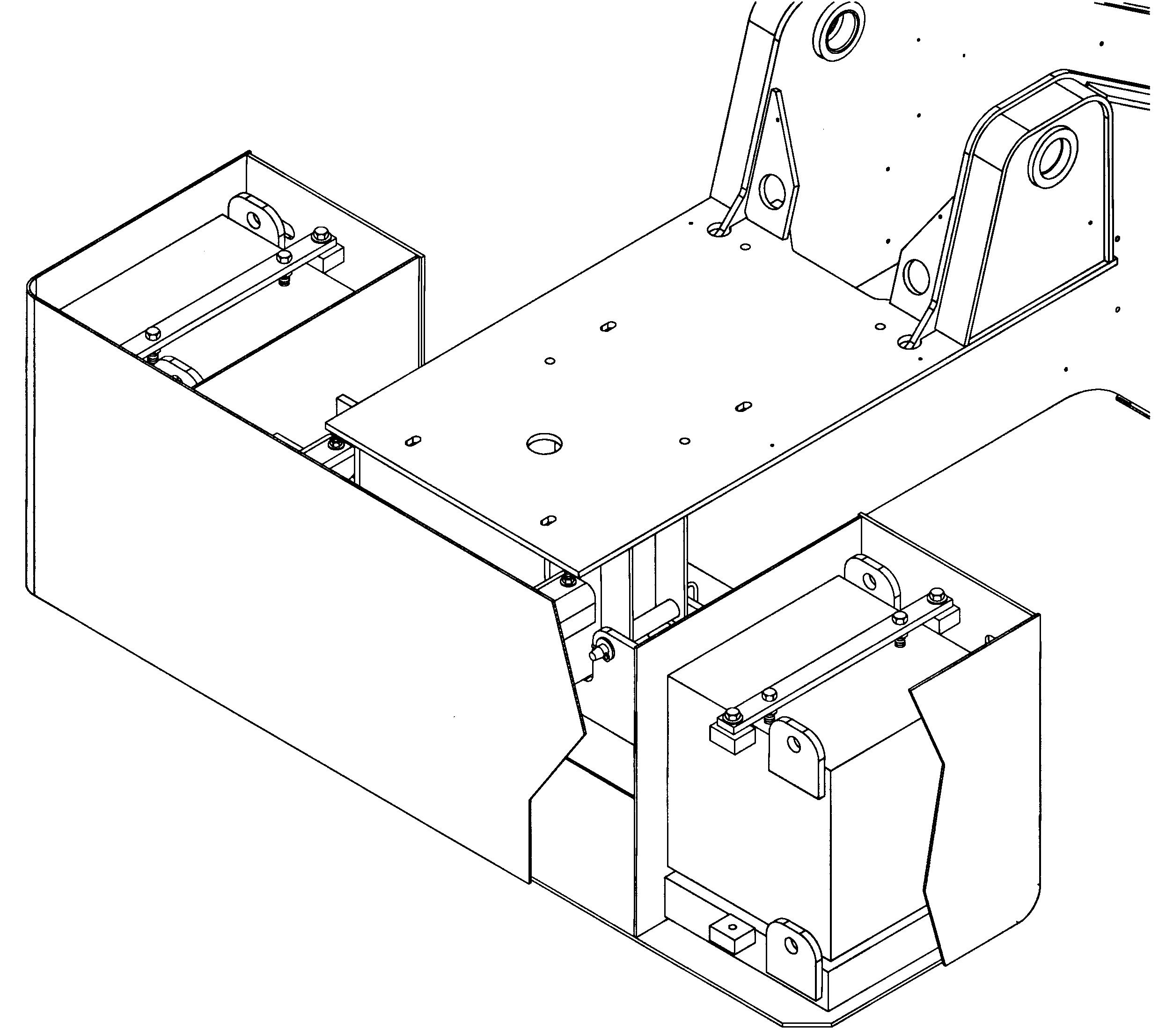
Counterweights
Description
There is a counterweight pinned to the rear of the superstructure and an optional counterweight bolted to the front bumper The superstructure mounted counterweight (Figure 5-5), depending on crane configuration, weighs either 1043 or 3175 kg (2300 or 7000 lb) The 1043 kg (2300 lb) counterweight consists of the basic 567 kg (1250 lb) shell and two 234 kg (515 lb) bolt in slabs The 3175 kg (7000 lb) counterweight consists of the 1043 kg (2300 lb) counterweight with two 1066 kg (2350 lb) bolt in slabs Sight slots in the front of the counterweight shell may be used to determine which counterweight configuration is installed The optional front bumper mounted counterweight (Figure 56), depending on crane configuration, weighs either 150 or 812 kg (330 or 1790 lb). The 150 kg (330 lb) counterweight is the basic shell The 662 kg (1460 lb) counterweight is the basic shell with a 512 kg (1130 lb) bolt in slab
For cranes without an auxiliary hoist, an additional 350 kg (772 lb) counterweight is bolted to the hoist mounting area in lieu of the auxiliary hoist
Maintenance
Superstructure Counterweight
Danger
Death or serious injury could result from being crushed by a falling counterweight.
Danger
Ensure the retainer pin is properly installed to secure the counterweight mounting pin
Removal
1. Fully extend and set the outriggers.
Caution
When lifting/handling the counterweight, keep the chains/ straps vertical to minimize side pull on the lifting lugs
NOTE: The use of a forklift to remove or install the Counterweight is not recommended
2 Attach and adequate lifting device to the counterweight lifting lugs adjacent to the mounting pins
3. Ensure the three counterweight leveling bolts are set for maximum clearance with the turntable
4. Take up any slack in the lifting chains and raise the counterweight just enough to remove any pressure on the counterweight mounting pins
5. Remove the retainer pins and washers that secure the counterweight mounting pins and remove the mounting pins
6. Lower the counterweight enough to clear the superstructure and remove the counterweight from the crane
Installation
1. Fully extend and set the outriggers
Caution
When lifting/handling the counterweight, keep the chains/ straps vertical to minimize side pull on the lifting lugs
NOTE: The use of a forklift to remove or install the Counterweight is not recommended
2. Attach an adequate lifting device to the counterweight lifting lugs and lift the counterweight into place on the superstructure, aligning the mounting holes on the counterweight to the holes in the superstructure
3 Install the mounting pins and secure them in place with the washers and retainer pins
4. Remove the lifting device from the counterweight
5 Using the three counterweight leveling bolts, level the counterweight and eliminate any relative movement between the counterweight and turntable Maximum height of counterweight shall not exceed 6,35 mm (0 25 in) out of level with the turntable base plate when measured from either counterweight outer edge.
Changing Weight Configurations
1 Remove the slabs as follows: a. Remove the two bolts, washer, and lockwashers securing the hold down strap to the slab b Remove the two bolts and washers securing the hold down strap to the mounting blocks on the shell
Caution
When lifting/handling the counterweight slabs, keep the chains/straps vertical to minimize side pull on the lifting lugs c. Attach and adequate lifting device to the counterweight slab lifting lugs and remove the slab from the counterweight shell d. If steps a thru c removed the large slabs, and the smaller slabs are to be removed, repeat step c for the smaller slabs e. If the smaller slabs are to remain in the shell, perform steps 2.c and 2.d.
NOTE: All the slabs have three foot pads welded to the bottom of the them, one on one side and two on the other When installing the slabs, always install them with the single pad to the outside
2 Install the slabs as follows:
Caution
When lifting/handling the counterweight slabs, keep the chains/straps vertical to minimize side pull on the lifting lugs a. Attach an adequate lifting device to the smaller counterweight slab lifting lugs and position the slab in the shell b. If the larger slabs are to be installed, repeat step a, if not proceed to step c.
Caution
The slab must rest on the bottom of the shell, or smaller slab and not be supported by the hold down strap c. Place the hold down strap on the slab and mounting lugs Install the two bolts, washers (as necessary to provide a gap between the mounting lugs and the hold down strap), and lockwashers securing the strap to the slab d. Secure the hold down strap to the mounting lugs with two bolts, and lockwashers
Front Bumper Mounted Counterweight
Removal
1 Remove the two bolts, washers, and lockwashers securing the slab in the counterweight shell
Caution
When lifting/handling the counterweight (Figure 5-6) or slab, keep the chains/straps vertical to minimize side pull on the lifting lugs
2. Attach and adequate lifting device to the counterweight slab lifting lugs and remove the slab from the counterweight shell
3. Attach and adequate lifting device to the counterweight shell lifting lugs
4. Remove the six bolts, washers, lockwashers, and nuts securing the counterweight shell to the front bumper and remove the shell.
Installation
Caution
When lifting/handling the counterweight or slab, keep the chains/straps vertical to minimize side pull on the lifting lugs
1. Attach an adequate lifting device to the counterweight shell lifting lugs and position the shell on the front bumper. Secure with six bolts, washers, lockwashers, and nuts
2. Attach and adequate lifting device to the counterweight slab lifting lugs and position the slab in the counterweight shell
3 Secure the slab to the shell with two bolts, washer, and lockwashers Torque the bolts 97 6 to 105 7 Nm (72 to 78 pounds-foot)