14 minute read
RT540E OPERATOR’S MANUALSET-UP AND INSTALLATION PROCEDURES


Upper Boom Nose Sheaves
Upper Boom Nose Sheaves
To
Hookblock Sheaves
Bottom Boom Nose Sheaves
Bottom Boom Nose Sheaves
Hookblock Dead End
Five Parts Line 3-Sheave Hookblock
Upper Boom Nose Sheaves
To Aux Hoist
Bottom Boom Nose Sheaves
Aux Nose Boom Nose Dead End
Six Parts Line
Upper Boom Nose Sheaves
Four Parts Line
Hookblock Dead End
Hookblock Sheaves
Hookblock Sheaves
Eight Parts Line 4-Sheave Hookblock
Bottom Boom Nose Sheaves
Hookblock Sheaves Boom Nose Dead End
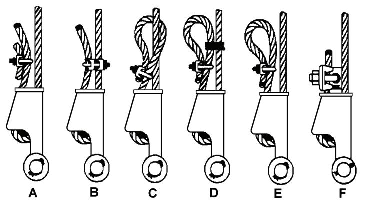
DEAD-END RIGGING/WEDGE SOCKETS
Wedge socket assemblies are popular rigging accessories and have been successfully used for decades to terminate wire ropes on mobile cranes. A wedge socket assembly is easily installed and dismantled but it must be installed and used correctly. It is essential to use only a wedge and socket of the correct size for the rope fitted. Failure to do so may result in the rope pulling through the fitting.
Since state and local laws may vary, alternate attachment methods may be necessary depending upon work conditions. If alternate methods are selected, the user is responsible and should proceed in compliance with the regulations in force. If there are any questions, contact your Manitowoc distributor or Manitowoc Crane Care.
Do not mix components from different manufacturers. The selection, installation and use of a wedge socket assembly must be in accordance with the requirements of the wedge socket manufacturer and the wire rope manufacturer upon whose wire rope the wedge socket assembly will be used.
Grove Crane specifies the size, type, class and line pulls for wire rope, predominately rotation resistant wire rope, and rigging accessories such as overhaul balls and hook blocks for use with each new crane that it manufactures. Other wire ropes and rigging accessories are available from various vendors. Different wire rope manufacturers have differing requirements for the construction, handling, cutting, seizing, installation, termination, inspection and replacement of the wire ropes they produce. Their advice should be sought for each specific type of wire rope a crane user intends to install on a mobile crane.
When assembly is complete, raise the boom to a working position with a load suspended to firmly seat the wedge and rope into the socket before the crane is used operationally.
Caution
If the socket is not positioned with the flat face toward the boom sections, structural damage will occur.
When anchoring the socket to the boom, ensure the flat face of the socket is in position, as shown, toward the boom sections (Figure 4-6).
Installing Wedge And Socket
1. Inspect the wedge and socket. Remove any rough edges and burrs.
2. Seize the end of the wire rope using soft or annealed wire or strand. If the end of the rope is welded, the welded end should be cut off. Do not weld on size 6x37 rope. This will allow the distortion of the rope strands, caused by the bend around the wedge, to adjust themselves at the end of the line. Refer to SECTION 1Introduction in the Service Manual for wire rope procedures.
3. Insert the rope into the socket, making sure the live-end (Figure 4-7) of the rope is directly in line with the ears of the socket and the direction of pull to which the rope will be subjected. If the rope is loaded into the socket incorrectly, under a load the rope will bend as it leaves the socket, and the edge of the socket will wear into the rope causing damage to the rope and eventual failure.
4. Form a loop in the rope, and route the rope back through the socket allowing the dead-end (Figure 4-7) to protrude from the socket. Ensure the dead-end of the rope is of sufficient length to apply end rigging to the dead-end after the wedge has been seated.
5. Insert the wedge into the loop and pull the live-end of the rope until the wedge and rope are snug inside the socket. Seat the wedge inside the socket by using the crane’s hoist to first apply a light load to the live-end.
6. After final pin connections are made, increase the loads gradually until the wedge is properly seated.
7. Apply dead-end rigging to the wedge socket assembly to restrain the wedge from becoming dislodged from the socket should the rope suddenly become unloaded due to the headache ball or hook block striking the ground, etc; refer to Dead-end Rigging, page 4-7
Dead-end Rigging
Sketches A through F (Figure 4-8) illustrate various ANSI approved methods for rigging the dead-ends of wire ropes which exit a wedge socket assembly. While use of the loopback method is acceptable, care must be exercised to avoid the loop becoming entangled with tree branches and other components during crane transport and with the anti-two block system and other components during use of the crane.
Of the methods shown below, Manitowoc prefers that method A or F be used, i.e., clipping a short piece of wire rope to the dead-end or using a commercially available specialty wedge. Typically, it is recommended that the tail length of the dead-end should be a minimum of 6 rope diameters but not less that 6in (15.2cm) for standard 6 to 8 strand ropes and 20 rope diameters but not less than 6in (15.2cm) for rotation resistant wire ropes.
When using method A, place a wire rope clip around the dead end by clamping a short extra piece of rope to the rope dead end. DO NOT CLAMP THE LIVE END. The U-bolt should bear against the dead end. The saddle of the clip should bear against the short extra piece. Torque the U-bolts according to the table titled Wire Rope Clip Torque Values (Table 4-1).
Other sources for information with which crane users should be familiar and follow is provided by the American Society of Mechanical Engineers, American National Standard, ASME B30.5, latest revised. ASME (formerly ANSI) B30.5 applies to cableways, cranes, derricks, hoists, hooks, jacks, and slings. It states, in section 5-1.7.3, “(c) Swagged, compressed, or wedge socket fittings shall be applied as recommended by the rope, crane or fitting manufacture.” Wire ropes are addressed in ASME B30.5, section 5-1.7.2, ROPES, it states, in pertinent part, “(a) The ropes shall be of a construction recommended by the rope or crane manufacturer, or person qualified for that service.” Additional information is published by the Wire Rope Technical Board in the Wire Rope Users Manual, latest revised edition.
Erecting And Stowing The Boom Extension
General Warnings
Danger
To prevent serious injury or death, always wear personal protective equipment; i.e., a hard hat, eye protection, gloves and metatarsal boots.
Danger
Boom angles are used to control speed at which extensions swing during erecting and stowage. Improper boom angles will cause uncontrollable swing speeds of extension.
NOTE: Tag line used in these procedures is to control the movement of the boom extension.
Danger
Before attempting to erect or stow the boom extension; read and strictly adhere to all danger decals installed on the boom/boom nose, boom extension, and stowage brackets.
Securing the Boom Extension with Tag Line (Rope)
NOTE: A tag line attached to the tip of the extension is used to control the movement of the boom extension.
Danger
Always secure the boom extension with a tag line (rope) on the main boom before removing any connections. This will prevent the extension from swinging around and knocking you off the carrier or injuring other persons in the swing range.
The extension may swing our on its own accord when you remove the last connection that held the extension at the side of the main boom.
You must therefore secure the extension before you begin the erection procedure.
Secure the boom extension as follows:
• Attached a tag line (rope) at the front of the extension.
• Have a helper hold the tag line (rope) tight while you are removing the last connection.
NOTE: If you are alone, secure the other end of the tag line (rope) on the crane (e.g., on the steps of the access ladder or to the superstructure. Leave enough play in the tag line that it is tight only when you swing the extension towards the main boom head later in the procedure.
Erecting
Danger
To prevent serious injury or death, do not stand on decking until extensions are secure.
1. Visually check to ensure all pins are installed.
2. Crane should be set up on outriggers using normal setup procedures. Refer to Section 3 - OPERATING CONTROLS and PROCEDURES.
a. Fully retract boom.
b. Lower boom to horizontal for erecting over the front of the crane.
NOTE: The auxiliary boom nose (rooster sheave) does not have to be removed. However, if reeved, the hoist cable must be removed from the sheave.
3. Rig either the main hoist or optional auxiliary hoist cable for single part line with nothing but the wedge socket on the end of the cable. Refer to Cable Reeving and Dead End Rigging in this section.
4. Remove the retainer clips from the right side attachment pins (1) stowed in the base of the boom extension (2) and remove the attachment pins from the boom extension. Insert the right side attachment pins (1) through the boom attachment and boom extension anchor fittings. Install the retainer clips in the attachment pins. (Figure4-9)
7. Raise the boom to horizontal and extend the boom approximately 51 to 64 cm (20 to 25”). Make certain that the boom extension stowage lugs clear the guide pins (Figure4-12) (3) and ramp (Figure4-10) (4) on the front and rear stowage brackets.
Danger
When erecting the boom extension, ensure that all personnel and equipment are kept clear of the swing path.
8. Slightly raise and/or lower the boom to help control the boom extension. Using the rope attached to the top of the boom extension, manually swing the extension into place ahead of the boom nose, engaging the attachment fittings (5) with the anchor fittings on the left side of the boom nose. (Figure4-13)
Danger
Do not modify the attachment points to permit the installation of the attachment pins.

Caution
Do not place blocking under the boom extension sheave wheel. Damage to the sheave wheel may occur.
9. Install the top left side attachment pin (6) and retainer clip into the upper anchor and attachment fittings of the boom nose. (Figure4-13)
10. Extend the boom extension alignment jack (7) until the lower left side boom nose and boom extension adapter lugs are aligned.
11. Install the bottom left side attachment pin (8) and retainer clip into the lower anchor and attachment fittings of the boom nose.
12. Connect LMI cables: a. Remove cable from boom extension. b. Remove dummy plug from junction box on the boom nose. c. Install cable end connector from the boom extension where dummy plug was removed
13. Release pressure on the boom extension alignment jack (7). (Figure4-13)
14. Install the Mast Assembly (9) in the upright position using the locking pin.
15. Reeve the hoist cable. Refer to Cable Reeving in this section.
Stowing
1. With crane set up on outriggers, fully retract the boom and swing to over-the-front.
2. Lower the boom to minimum elevation.
3. Remove the cable retainer pin from the boom extension tip and the mast assembly. Remove the hoist cable from the sheaves. Install the cable retainer pins.
4. Remove the mast assembly retainer pin and the pin securing the mast assembly in the upright position (9). (Figure4-13) Lay the mast assembly over to the stowed position. Insert the pins securing the mast to the base section.
5. Attach a length of rope to the boom extension tip.
6. Disconnect LMI cable: a. Remove connector from junction box on boom nose. b. Install dummy plug in junction box. c. Route cable to and attach to boom extension
7. Raise the boom to horizontal.
8. Extend the boom approximately 51 to 64 cm (20 to 25”). Make certain that the boom extension stowage lugs will line up in front of the guide pins (3) (Figure4-12) and ramp (4) (Figure4-10) on the stowage brackets when the boom extension is positioned to the side of the boom.
9. Ensure the hitch pin (3) (Figure4-10) and clip pin are removed from the rear stowage bracket.
10. Extend the boom extension alignment jack (7) (Figure413) until the bottom left side attachment pin (8) is free. Remove the bottom left side boom extension clip pin and attachment pin.
11. Release pressure on the boom extension alignment jack. Completely retract the jack.
12. Remove the top left side attachment pin (6) and clip pin from the upper anchor and attachment fittings of the boom nose.
Danger
When stowing the boom extension, ensure that all personnel and equipment are kept clear of the swing path.
Caution
Do not allow the boom extension to slam into the stowage bracket when swinging into the stowed position.
13. Using the rope attached to the tip of the boom extension, manually swing the extension to the side of the boom.
14. Align the stowage lugs on the boom extension with the guide pins and ramp on the stowage brackets (Figure410) and (Figure4-12) and fully retract the boom.
15. Install the hitch pin (2) (Figure 4-10) and clip pin securing the boom extension to the rear stowage bracket.
16. Remove the attachment pins (1) and clip pins from the anchor and attachment fittings on the right side of the boom nose (Figure4-9) and stow them in the base of the boom extension. Stow left side attachment pins and clips in outside attachment fitting on swingaway.
17. On the rear stowage bracket, remove the pin securing the sliding support in the “OUT” position. Push in on the handle (10) (Figure 4-14) to push the swingaway against the rear of the boom and disengage the swingaway anchor fittings from the boom nose attachment lugs (9) (Figure 4-9). Install the retainer pin (11) (Figure 4-14) securing the sliding support in the “IN” position.
18. Rig the boom nose and hoist cable as desired and operate the crane using normal operating procedures.
Setting The Offset
Caution
The mast assembly must be positioned on top of the base section before attempting to offset the swingaway to 30 degrees. Failure to do so can cause damage to the mast and/or swingaway adapter.
1. Extend and set the outriggers. Swing the boom over to the front of the crane.
2. To set the offset from zero degrees (0°) to thirty degrees (30°), perform the following:
Caution
Do not overload the swingaway or the attachment points when lowering the boom.
a. Slowly lower the boom until the tip of the swingaway is on the ground and the pressure on the offset pin is relieved.
b. Remove the lock pin, two washers, and offset pin (12). (Figure 4-15) c. Slowly elevate and telescope the boom at the same time until the offset shaft takes the full load of the swingaway.
3. To set the offset from thirty degrees (30°) to zero degrees (0°), perform the following: a. Slowly lower the boom until the tip of the swingaway is on the ground and the offset pin can be installed. b. Install the offset pin, two washers, and lock pin (12). (Figure 4-15) c. Raise the boom and operate as desired.
Changing Boom Extension From Telescoping Type To Fixed Type
1. Erect the boom extension.
2. Position the boom to horizontal.
3. Disconnect the anti-two block cable connector from the junction box.
4. Remove the telescoping section hitch pin and retaining pin.
NOTE: The telescoping section weighs approximately 250 kg (551 lb).
5. Extend the telescoping section and attach an adequate lifting device to support the telescoping section. Remove the stop bolts from the base section and remove the telescoping section from the base.
NOTE: The pin-on boom extension nose weighs approximately 60 kg (132 lb).
6. Using a adequate lifting device, position the pin-on boom extension nose in the base section and secure with the two pins and hitch pins.
7. Connect the anti-two block cable connector to the junction box.
Setting The Telescoping Extension Length
Extending
1. Position the boom to over the front.
2. Lower the boom to horizontal.
3. Remove the loop of anti-two block cable from the spool on the side of the base section and let the cable hang free.
4. Remove the hitch pin and retainer pin securing the telescoping section in the base.
5. Carefully pull the telescoping section from the base until the holes in the base and telescoping section lineup. Install the retainer pin and hitch pin.
6. If not already reeved, reeve the hoist cable over the mast and boom extension nose sheave. Install all cable retainer pins.
Stowing
1. Unreeve the boom extension nose.
2. Position the boom to horizontal.
3. Remove the hitch pin and retainer pin securing the telescoping section in the base.
4. Push the telescoping section into the base and secure with the retainer pin and hitch pin.
5. Loop the anti-two block cable over the spool on the side of the base section.
Counterweights
Counterweight Description
The counterweight is pinned to the rear of the turntable and weighs 4300 kg (9490 lb). For cranes without an auxiliary hoist, an additional 350.6 kg (773 lb) counterweight is bolted to the hoist mounting area in lieu of the auxiliary hoist.
Counterweight Removal
Danger
Death or serious injury could result from being crushed by a falling counterweight.
Danger
Ensure the retainer pin is properly installed to secure the counterweight mounting pin.
NOTE: Use of a forklift to remove/install the fixed counterweight is not recommended.
NOTE: Refer to (Figure 4-16) for counterweight removal.
Fabricated Counterweight
ItemDescription
1Counterweight
2Primary Retainer Pin Assembly
3Leveling Capscrew
4Turntable
5Grill (not on cast counterweight units)
1. Fully extend and set the outriggers.
2. Rotate the superstructure so the counterweight is over the front of the carrier to gain additional clearance. Engaging the pin type turntable lock will aid alignment.
NOTE: The counterweight weighs approximately 4300 kg (9490 lb).
NOTE: For cast counterweight configurations (Figure 414) remove polyurethane plugs from the two upper threaded inserts (7) before inserting eyebolts (two 1-1⁄4X 7UNC eyebolts are needed.)
3. Lower and fully retract the boom
4. Shut down crane.
5. Remove and cap hydraulic lines from auxiliary hoist (if installed)
6. Attach an adequate lifting device to the counterweight.
7. For cast counterweight; remove the redundant pin assembly (6) prior to removing the primary retainer pin assembly (2).
8. Slowly raise counterweight until primary retainer pin assembly (2) can be removed by pushing and turning the pin.
9. Remove primary retainer pin assembly (2) from opposite side.
10. Slowly raise counterweight until pin assembly can be removed by pushing and turning the pin.
11. Remove pin assembly from opposite side.
12. Replace primary retainer pin assembly (2) in turntable
13. Back counterweight away from turntable until it is clear of crane.
14. Replace pin assembly in turntable counterweight mounting lugs.
15. Move counterweight far enough from crane to allow the turntable/superstructure to clear during repositioning.
16. Rotate superstructure to the normal travel position.
Counterweight Installation
1. Fully extend and set the outriggers.
2. Rotate the superstructure so the counterweight will be over the front of the carrier to gain additional clearance.
3. Shut down crane.
4. Remove and cap hydraulic lines from auxiliary hoist (if installed).
Caution
When lifting/handling the counterweight, keep the chains/ straps vertical to minimize side pull on the lifting lugs.
NOTE: The counterweight weighs approximately 4300 kg (9490 lb).
NOTE: Use of a forklift to remove/install the fixed counterweight is not recommended.
5. Attach an adequate lifting device to the counterweight and lift the counterweight into place on the superstructure, aligning the mounting holes on the counterweight to the holes in the superstructure.
6. Install the counterweight primary retainer pin assemblies (2) and secure them in place. Note: With cast counterweight re-install the two redundant pin assemblies (6).
7. Remove the lifting device from the counterweight.
8. Using the four counterweight leveling capscrews (3), level the counterweight and eliminate any relative movement between the counterweight and turntable. Maximum width of counterweight shall not exceed 6.0 mm (0.25 in) out of level with the turntable bearing when measured from either counterweight outer edge