8 minute read
Product and Component Plate Locations


Product
Controls And Safety Equipment
Become familiar with and know how to use all safety devices and controls on the skid-steer loader before operating it. Know how to stop loader operation before starting it. This Gehl loader is designed and intended to be used only with Gehl attachments or Manitou Americas-approved referral attachments or accessories. Manitou Americas cannot be responsible for operator safety if the loader is used with nonapproved attachments.
Guards and Shields
Whenever possible and without affecting loader operation, guards and shields are provided to protect against potentially hazardous areas. In many places, safety decals are also provided to warn of potential hazards and/or to display special operating procedures.
Read and thoroughly understand all safety decals on the loader before operating it. Do not operate the loader unless all factory-installed guards and shields are properly secured in place.
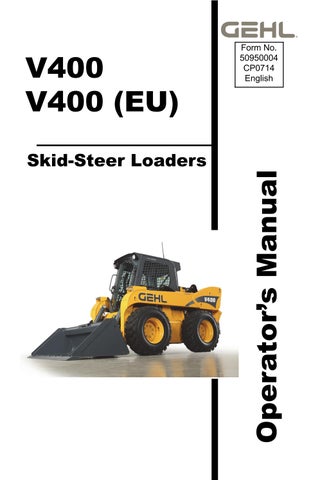
Operator Restraint Bar
Lower the operator restraint bar after entering the operator’s compartment and sitting in the seat. The restraint bar is securely anchored to the ROPS/FOPS. The operator must be seated with the restraint bar in its lowered position to start or operate the skid-steer loader. Refer to Safety Interlock System on page20 for more information.
The dual joystick and hand/foot loaders restraint bar provides for-aft adjustment that allows the operator to determine the most comfortable position of the restraint bar. The right and left portions of the restraint bar system can be adjusted independent of one another by pushing the lever on the lower inside of either pad. The restraint pad can then be used to adjust to the desired position. The restraint pad locks in place when it is released. T-Bar loaders do not have an adjustable restraint bar.
Warning Warning Warning
Never defeat the operator restraint bar or seat switch electrically or mechanically. Always wear the seatbelt.
Operator’s Seat
The seat is mounted on rails for rearward and forward repositioning. A springloaded lever unlocks the seat position adjustment mechanism.
Suspension seat: A weight adjustment knob is provided for individual operator adjustment.
Air Suspension Seat (optional): Adjust air suspension seat by pushing in the knob on the air seat to increase the amount of suspension. Pull knob out to release air and decrease the suspension level.
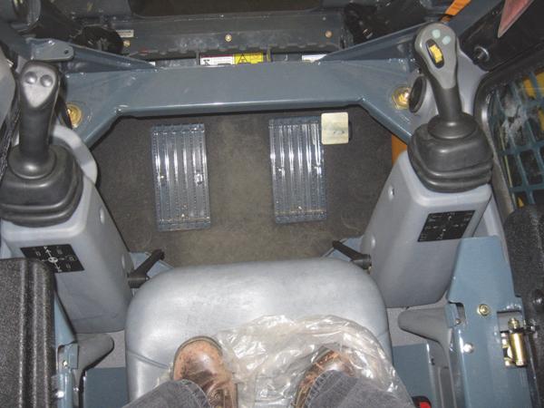
Upper-Torso Restraint
1. Restraint Bar
2. Seatbelt
3. Seat Position Adjustment Lever
4. Suspension Seat Weight Adjustment Knob (optional)
Always wear the upper-torso restraint when operating in High speed.
The seatbelt should always be fastened during operation.
Important: Inspect the seatbelt(s) for damage before use, and replace if damaged. Keep seatbelt(s) clean. Use only soap and water to wash seatbelt(s). Cleaning solvents can cause damage to seatbelt(s).
Safety Interlock System
Hydraloc™
NEVER defeat the safety interlock system by mechanically or electrically bypassing any switches, relays or solenoid valves.
An interlock system is provided on the loader for operator safety. Together with solenoid valves, switches and relays, the interlock system:
Prevents the engine from starting unless the operator is sitting on the seat and the operator restraint bar is lowered.
Disables the lift arm, auxiliary hydraulics, attachment tilt and wheel drives whenever the operator leaves the seat, turns the keyswitch to OFF or raises the restraint bar.
Note: The auxiliary hydraulic circuit can be detented in the “on” position for continuous operation with the restraint bar raised and operator out of the seat. (See Auxiliary Hydraulic Controls, page41.)
Testing the Safety Interlock System
Before exiting the machine, check the safety interlock system for proper operation:
Restraint Bar
With the engine running, raise the restraint bar. Test each of the controls. There should be no more than a slight movement of the lift arm, hitch and machine. If there is any significant movement, troubleshoot and correct the problem immediately. Contact your dealer if necessary.
Seat Switch
With the engine off and the restraint bar lowered, unfasten the seatbelt, and lift your weight off the seat. Try to start the engine. If the engine starts, turn off the engine, troubleshoot and correct the problem. Contact your dealer if necessary.
ROPS/FOPS
The ROPS/FOPS (Roll-Over/Falling Object Protective Structure) is designed to provide protection for the operator from falling objects and in a tip over accident, if the operator is secured inside the operator’s compartment by the seatbelt and restraint bar.
WARNING
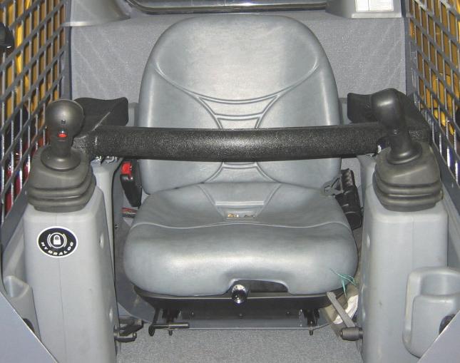
Parking Brake
Never operate the loader with the ROPS/FOPS removed or locked back.
This skid-steer loader is equipped with a spring-applied, hydraulic-released parking brake. The parking brake engages when the operator lifts the restraint bar, exits the seat or shuts off the engine. The brake can also be applied manually by using the switch located on the left instrument panel. A red indicator in the switch lights when the parking brake is applied.
Horn
On dual joystick and hand/foot loaders, pressing the right button on the left control handle sounds the horn. On t-bar loaders, pressing the bottom button on the left control handle sounds the horn.
Rear Window Emergency Exit
The ROPS/FOPS rear window has three functions: noise reduction, flying objects barrier and emergency exit.
To use the emergency exit, pull on the yellow warning tag at the top of the window and remove the seal. Push or kick out the window and then exit.
See your local automotive glass specialist to reinstall the window.
Lift Arm Support Device
The lift arm support device is used as a cylinder lock to prevent the raised lift arm from lowering unexpectedly. Be sure to install the support device when the lift arm is raised for service. When the support device is not being used, return it to its storage position. The support device is a safety device, which must be kept in proper operating condition at all times. The following steps ensure correct usage: With the key switch OFF and the solenoid valve working properly, the lift arm will stay raised when the lift control is moved to lower the lift arm. If the valve does not hold the lift am and it begins to lower do not leave the operator’s compartment. Instead, lower the lift arm and exit the machine. Then, contact your Gehl dealer immediately to determine why the lift arm lowers while the key switch is OFF.
Warning
Installation
To install the lift arm support device:
1.Raise the lift arm to near full height.
2.Stop the engine.
3.Move the lift arm control to “lower” to verify that the lift arm is being held in the raised position by the safety interlock system.
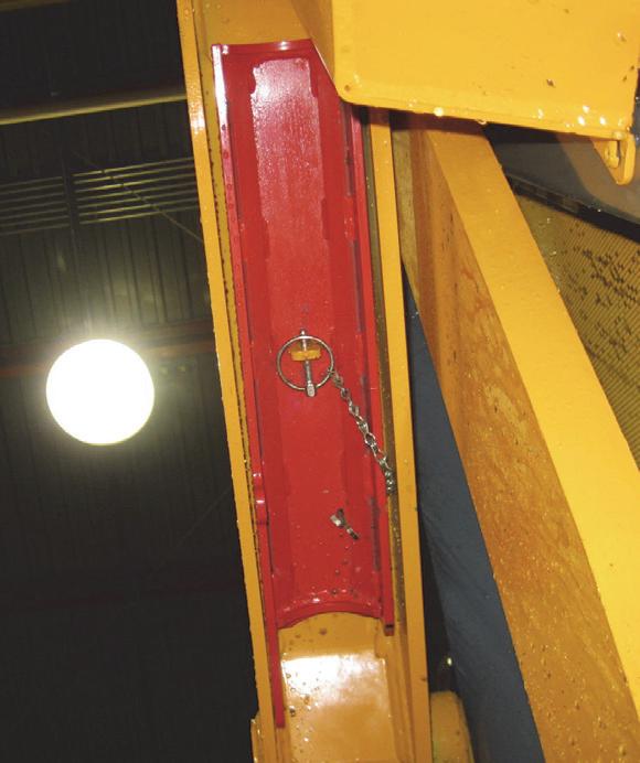
4.Have an assistant remove the lift arm support device from its storage location (Figure4) on the left side of the machine and install the lift arm support device on the left lift cylinder (Figure3).
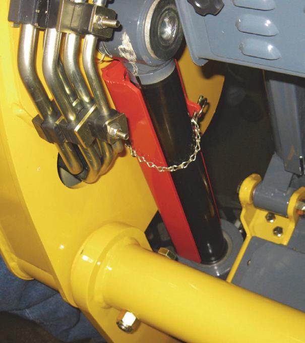
5.Secure the support device to the lift cylinder rod with the attached lock pin and chain.
6.Restart engine.
7.Slowly lower the lift arm until it engages and locks against the lift arm support device.
8.Stop the engine, and exit the machine.
Removal
The safest method of installing and removing the lift arm support device requires two people – one person inside the loader and another person outside the loader to install the support device.
Warning
To return the lift arm support device to its storage position:
1.Start the engine;
2.Raise the lift arm fully;
3.Stop the engine;
4.Verify that the lift arm is being held in the raised position by the safety interlock system.
Warning
With the key switch OFF and the solenoid valve for the safety interlock system functioning properly, the lift arm will stay raised when the lift control is moved to “lower”. If the lift arm moves, do NOT leave the operator’s compartment. Instead, have an assistant remove the support device for you. Then, contact your Gehl dealer to determine the reason why the lift arm lowers while the key switch is in the OFF position.
5.Have an assistant remove the lift arm support device.
6.Lower the lift arm and secure the lift arm support device with the lynch pin in the storage location (Figure4).
Accessory Plug
The 12-V accessory plug is located at the bottom of the right instrument panel.
Dome Light
The dome light is located on the right side of the ROPS/FOPS headliner. Push on the dome light to switch it on.
Work Lights
Loaders have two sets of work lights. The front work lights are located at the top of the ROPS/FOPS. The rear work lights are located at the top of the rear door.
Heater (optional)
Loaders with the optional heater have two control knobs on the left instrument panel for controlling fan speed and heater temperature (see Figure5).
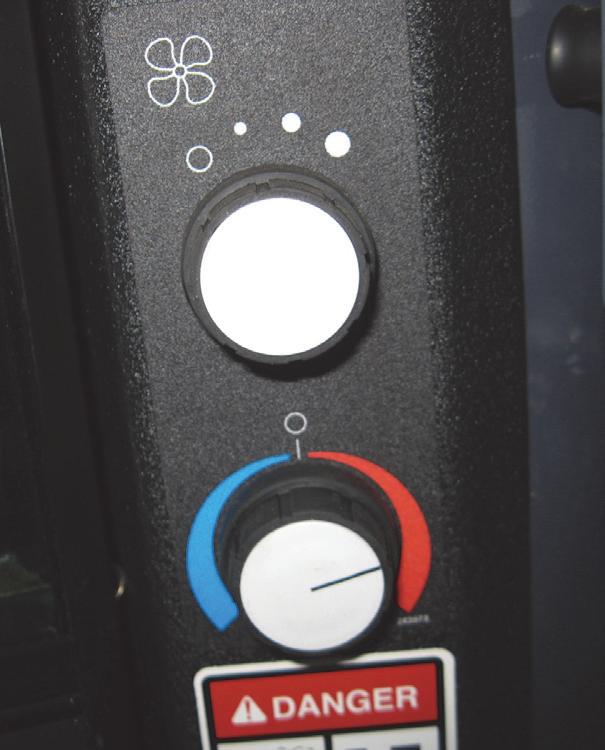
1. Fan Speed Control: Controls the air flow.
2. Temperature Control: The potentiometer switch is a rotary dial for control of heat functions.
Heater and Air Conditioner (optional)
Loaders with the combination heater/air conditioner have two control knobs on the left instrument panel for controlling fan speed and heater/air conditioner temperature.
1. Fan Speed Control: Controls the air flow.
2. Temperature Control: The potentiometer switch is a rotary dial for control of heat and air conditioning functions.
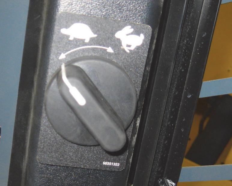
Engine Speed Control
An engine speed control (Figure6) is provided for setting the engine speed. Move the control clockwise to increase the engine speed, and counter-clockwise to decrease the engine speed.
With dual joystick and t-bar controls, a foot pedal (Figure7) is provided as a secondary throttle, which can be used to override the engine speed control. If the foot throttle is released, the engine will return to the speed set by the engine speed control.
Two-Speed Drive (Travel Mode Only)
Dual joystick and hand/foot loaders use the left button on the left control handle for shifting between High (H) and Low (L). T-Bar loaders use the top button on the left control handle. Shifting to High allows the machine to exceed 6.42mph (10,3km/h), up to a maximum speed of 12.5mph (20km/h). When the loader is in High (H) an H icon on the Indicator and Warning Light Display (page27) will illuminate. Press the button once to activate, and again to deactivate.
Note: Speed varies slightly with tire size.
When two-speed drive is activated, down shifting to single-speed drive while traveling at full speed is not recommended and damage may result.
Warning Warning Warning
Hydraglide™ Ride Control System
Dual joystick and hand/foot loaders use the right button on the right control handle for shifting between normal mode and ride control mode. T-Bar loaders use the top button on the right control handle. The ride control system provides a smoother ride over uneven surfaces. Press the button once to activate the system, and again to deactivate. The ride control system is automatically deactivated when the machine is shut off.
When ride control is activated, the lift arm may drop slightly without a load, or several inches with a heavy load.
Float Control
Dual joystick and hand/foot loaders use the top middle button on the right control handle for shifting between normal mode and float mode. T-Bar loaders use the bottom button on the right control handle. This mode allows the lowered lift arm to follow the ground contour while traveling over changing ground conditions. Press and hold the button for ten seconds or longer to detent, and press again to deactivate. The float mode is automatically deactivated when the machine is shut off.
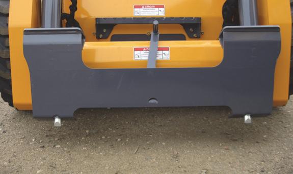
Attachment Mounting
The skid-steer loader is equipped with either the standard manual All-Tach® hitch or optional Power-A-Tach® hitch for mounting a bucket or other attachments (Figure8).
All-Tach® Hitch
A manual latch lever engages the latch pins. While standing outside the machine, rotate the lever all the way to the left to engage the latch pins. Rotate the lever (as viewed from the front) all the way to the right to disengage the latch pins. (Refer to page47 for more information.)
Warning
To prevent unexpected release of the attachment from the hitch, be sure to secure the latch pins by rotating the lever all the way to the hitch.
Power-A-Tach® System
One switch is used to operate the Power-A-Tach System hitch. The hitch will not operate if the parking brake switch is activated or if the restraint bar is in its vertical (open) position. (Refer to page47 for more information.)
To retract the hitch pins:
Press up on the Power-A-Tach switch on the right instrument panel.
To extend the hitch pins:
Press down on the Power-A-Tach switch on the right instrument panel.
To prevent unexpected release of the attachment from the hitch, be sure the latch pins are secure by verifying that the pin flags have moved fully to the outside of the hitch.