57 minute read
Attachment and Auxilliary Hydraulics Pilot-Pressure Apply Valves


Frame Level Control: This control is located to the rear of the tri-function joystick. The machine may be tilted slowly as much as 10° to the left or right to level the frame and boom in relation to the ground.
Warning
DO NOT level the frame with the boom raised or extended. Only level the frame while stopped and with the boom fully retracted and the attachment raised just enough to clear the ground.
Outrigger Switches: The outriggers are used to provide greater stability in specific applications. Press the left switch forward to lower the left outrigger. Press the right switch forward to lower the right outrigger. Press both switches rearward to raise the outriggers.
Level the frame before lowering the outriggers. Lower the outriggers until the front tires just start to raise.
Warning
For maximum machine stability, never lower the outriggers so that the tires come completely off the ground.
Do not use outriggers on soft or uneven surfaces. Be sure the surface can support the machine and load.

Be sure NO persons or equipment are where the outrigger pads will be positioned.
DO NOT travel with the outriggers extended under any circumstances.
Adequate clearance is required for the outriggers in the retracted position when traveling through doorways or narrow pathways.
DO NOT attempt to use outriggers as a hydraulic jack for maintenance or frame leveling or other similar uses.
Failure to heed could result in death or serious injury.
Function Indicators
Frame Level Indicator: Located in front of the operator on the ROPS upper cross tube, the position of the ball indicates when the frame is level relative to a sloping ground surface.

Frame Level Indicator
Boom Angle Indicator: Mounted on the left side of the outer boom, the movement of a ball indicates the angle of boom elevation relative to the ground.
Service And Safety Features
Transmission Oil Level: Dipstick is located below the cover on the front section of the main hood.
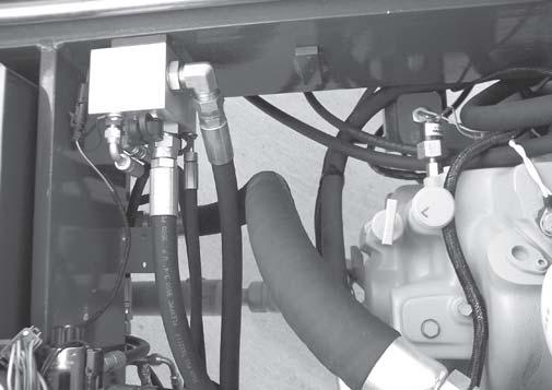
Hydraulic Pressure Test Ports: A gauge can be attached to these ports to check main hydraulic valve, joystick and steering pressures.
Hydraulic Reservoir Oil Level and Fill Cap: The sight gauge on the side of the reservoir indicates the level of the hydraulic oil. The fill cap is accessible by removing the cover of the front hood section.

Engine Oil Level: Dipstick is located on the right side of the middle section of the main hood.
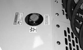
Coolant Level: Coolant can be checked and added through the radiator cap located under the top rear opening on the main hood.
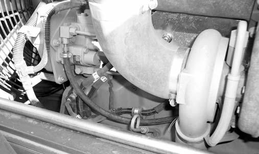
Air Cleaner Restriction Indicator: Located in the rubber connector at the rear of the air cleaner, it indicates when the air cleaner needs service. If the clear portion of the indicator is red, the air cleaner should be checked for a clogged filter element.
Backup Alarm: Located inside the rear frame cover, it produces a loud warning sound when the machine is in reverse.
Side-View Mirror: Located on the front outside corner of the fuel tank, this mirror provides the operator with a view toward the rear of the machine.
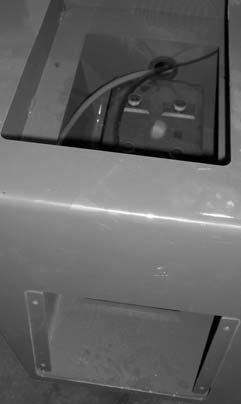
Battery Compartment: The battery compartment is below the tool box at the rear of the fuel tank. Remove the bottom panel of the tool box to check the electrolyte level. Remove the access panel on the side of the battery compartment to remove the battery.
FUSES:
1.15 AMP fuse: Ignition Switch, Horn, Brake Lights, and Clutch Cutout
2.20 AMP fuse: Transmission, Park Brake, PWP, Steer Mode, and Backup Alarm
3.15 AMP fuse: Lights, Ether, and Outriggers
4.25 AMP fuse: Heater and Gauges
5.25 AMP fuse: Top Wiper Motor
6.25 AMP fuse: Front Wiper Motor
RELAYS:
A.20/40 AMP change-over relay: Ignition
B.20/40 AMP change-over relay: Ignition
C.20 AMP relay: Front Wiper
D.20 AMP relay: Park Brake
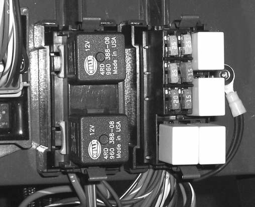
E.20 AMP relay: Lights
F.20 AMP relay: Top Wiper
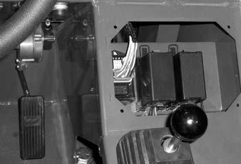
Fuse and Relay Compartment: This compartment is located under the load chart panel. Remove the four screws to gain access to the fuses and relays.
Attachment Tools
Gehl offers a versatile range of attachment tools to meet various lifting and material-handling applications. Contact your Gehl dealer for specifications and ordering information.
Accessories
Gehl offers a range of special accessories for this machine. Contact your Gehl dealer for specifications and ordering information.
Fuses and Relays Functions: Refer to the illustration and following description for the fuse and relay functions.
NOTE: All accessories are field-installed unless otherwise noted. Information and parts for installing accessories will be provided by the Gehl Company or Gehl Telescopic Handler dealers.
Chapter 6
Operation And Adjustments
General Information
Caution
BEFORE starting the engine and operating the Telescopic Handler, review and comply with ALL safety recommendations in the SAFETY chapter of this manual. Know how to STOP the machine before starting it. Also, BE SURE to fasten and properly adjust the seatbelt.
ENGINE BREAK-IN
A new engine does not require extensive “break-in.” However, for the first 100 hours of operation, follow these guidelines: Allow the engine to idle for a few minutes after every cold start. DO NOT idle the engine for long periods of time. DO NOT operate the engine at maximum power for long periods of time. Check the oil level frequently and replenish as necessary with the oil specified in the engine manual.
John Deere engines use a “break-in” oil for the first 100 hours of operation. After the first 100 hours of operation, change the oil and replace the oil filter. Consult the Lubrication chapter for the type and grade of oil to use. Refer to the Service and Storage chapter for the proper service intervals.
Prestart Inspection
It is the operator’s responsibility to inspect the machine before the start of each workday. Every prestart inspection must include more than simply checking the fuel and oil levels. It is a good practice to personally inspect any machine you are assigned to use, even though it has already been put into service by other personnel.
The most efficient method of checking a machine is by conducting a “Walk-Around Inspection.”
Before mounting the operator’s compartment, walk completely around the machine to be sure no one is under, on, or close to it. Let others in the area know you are going to start up. Wait until everyone is clear of the machine before starting it up.
Before Starting Engine
Before starting the engine and running the machine, refer to the Indicators and Controls chapter and become familiar with the various operating controls, indicators and safety features.
Starting The Engine
Warning
ALWAYS fasten the seat belt BEFORE starting the engine. Leave the parking brake applied until the engine is running and you are ready to operate the machine.
The following procedure is recommended for starting the engine:
1.Grasp the handholds and step up into the operator’s compartment.
2.Adjust the seat and fasten the seatbelt.
3.Check that all controls are in their “neutral” positions, except the parking brake switch, which should be in the “ON” position.
4.Turn the key switch to the “ON” position and press the start button. If the button is released before the engine starts, turn the key switch to the “OFF” position, and allow the starter to stop before attempting to start again.
IMPORTANT: Crank the starter until the engine starts. If the engine fails to start within 30 seconds, return the key to the “OFF” position, wait two minutes, and try again to start the engine. Cranking the engine for longer than 30 seconds will result in premature failure of the starter.
5.After the engine starts, allow a sufficient warm-up time before operating the controls.
NOTE: When the parking brake switch is pressed into the “OFF” position, the parking brake will remain applied until the travel lever is placed into either “Forward” or “Reverse.”
6.Check that indicators are in normal condition.
7.Check that there are no fuel, oil or engine coolant leaks, and no abnormal noises or vibrations.
Cold Starting Procedures
The engine is equipped with a block heater. This block heater or other starting aid is required for starting in temperatures below 32°F (0°C). See your Gehl dealer for additional starting aids.
For proper use of starting aids, check the instructions in the engine manual.
If the battery becomes discharged and has insufficient power to start the engine, jumper cables can be used for starting assistance. Refer to the jump starting instructions in the Service and Storage chapter of this manual for safe jump starting procedures.
Stopping
The following procedure is the recommended sequence for stopping the machine:
1.Bring the machine to a stop on a level surface. Avoid parking on a slope, but if necessary park across the slope and block the wheels.
2.Fully retract the boom and lower the attachment to the ground. Idle the engine for gradual cooling.
3.Place controls in neutral. Apply the parking brake.
4.Turn the ignition switch key to the “OFF” position. Remove the key.
5.Unfasten the seatbelt, and grasp the handholds while climbing out of the operator’s compartment.
First Time Operation
Make sure the engine is warm, and then go through the following procedures:
Caution
Be sure the area used for test-running is clear of spectators and obstructions. Initially, operate the machine with an empty attachment tool.
Place the travel lever in Forward or Reverse and select a speed range. Switch off the parking brake and move ahead slowly, while testing the steering and brakes. Stop and operate all boom, attachment tool functions and frame leveling controls, checking for smooth response.
Apply the service brakes, stop the machine and move the travel lever to the opposite direction.
Shifting to the next higher gear may be done at any engine speed while the machine is in motion.
DO NOT overspeed the engine when down-shifting. Allow the machine to slow down before shifting to the next lower gear.
Engine Shutdown Protection
The engine is equipped with a WARNING and SHUTDOWN feature to warn of low engine oil pressure and high engine coolant temperature. If the problem is not corrected, the engine power will be reduced automatically, or the engine will shut down.
Engine Oil Pressure
There are two low oil pressure protection features: Low Oil Pressure WARNING, and Low Oil Pressure SHUTDOWN.
At the Low Oil Pressure WARNING set-point, the warning lamp in the engine override switch will flash and a slow engine power derate will begin. But if the oil pressure rises above the Low Oil Pressure WARNING set-point, power will slowly increase until the engine is back to full power. The lamp will continue to flash until the power has returned to normal, even if the fault condition has been corrected and the recovery is in process.
At the Low Oil Pressure SHUTDOWN set-point, the lamp in the engine override switch will light continously, and a fast engine power derate will begin. If the oil pressure does not rise above the SHUTDOWN setpoint within 30 seconds, the engine will shut down. However, if the oil pressure rises above the Low Oil Pressure SHUTDOWN set-point within 30 seconds, then the power derate speed will revert to the Low Oil Pressure WARNING speed of reaction.
Engine Coolant Temperature
There are two coolant temperature protection features: High Coolant Temperature WARNING, and High Coolant Temperature SHUTDOWN.
At the High Coolant Temperature WARNING setpoint, the warning lamp in the engine override switch will flash and a slow engine power derate will begin. But if the coolant temperature drops below the High Coolant Temperature WARNING set-point, the power will increase slowly until the engine is back to full power. The lamp will continue to flash until the power has returned to normal even if the fault condition has been corrected and the recovery is in process.
At the High Coolant Temperature SHUTDOWN setpoint, the lamp in the engine override switch will light continously, and a fast engine power derate will begin. If the coolant temperature does not drop below the SHUTDOWN set-point within 30 seconds, the engine will shut down. Howerver, if the coolant temperature drops below the High Coolant Temperature SHUTDOWN set-point within 30 seconds, then the power derate speed will revert to the High Coolant Temperature WARNING speed of reaction.
Parking Brake
NOTE: The parking brake mechanism within the front axle is NOT designed for, OR intended to be used as, the primary means of stopping movement of the machine. Hydraulic braking provided through the service brakes within the axles is the primary means for stopping movement. The axleby-axle split brake system is the secondary means of stopping movement.

The proper sequence for correct machine operation is to always engage the parking brake switch before shutting off the engine; and to disengage the parking brake ONLY after the engine is running. In an EMERGENCY, if it becomes necessary to STOP movement, activate the parking brake switch to “ON.”
Changing Attachment Tools
The Telescopic Handler boom nose will accept Quickattach System Gehl attachment tools. The Quick-attach System has a quick-release hookup and locking mechanism for mounting framing-type or masonry-type attachment tools to the boom nose.
Quick-attach System Attaching Detail
Attaching
To pick up the attachment tool proceed as follows:
1.Raise the boom slightly, extend it two to three feet (600 to 900 mm) for better visibility, and tilt the Quick-attach System forward.
2.Align the Quick-attach System squarely with the back of the attachment tool.
3.Slowly extend the Quick-attach System and lower the hooks under the attachment tool hookup bar.
4.Tilt the Quick-attach System back so that the lock plate engages the attachment tool. This secures the attachment tool to the Quick-Attach system.
5.For an attachment tool with auxiliary hydraulics, connect the hoses to the quick-disconnect connectors on the boom nose.
Detaching
To detach attachment tool, proceed as follows:
1.Raise the boom slightly and extend it two to three feet (600 to 900 mm) for better visibility. Lower the boom until the attachment tool is approximately 12” (0.3 m) off the ground.
Quick-attach System Detaching Detail
2.Tilt the carrier rearward as far as it will go. Once the carrier is tilted back all the way, perform the Mandatory Safety Shutdown Procedure (p. 8, Safety chapter).
3.With the engine off, leave the operator’s station. Manually raise the lock spring and flip the lock plate up and outward at least 180° so it is in position to re-lock on the next attachment tool.

4.Tilt the Quick-attach System forward to allow the attachment tool to roll out, then lower the boom so the hook ears clear the hookup bar on the attachment tool.
NOTE: One side of the lock plate has a bright red decal to indicate the unlocked position.
5.If the attachment tool has auxiliary hydraulics, disconnect the hoses from the quick-disconnects on the boom nose.
6.Start the engine and tilt the Quick-attach System forward, then slowly back the machine until the attachment tool is free from the boom nose.
Warning
Modifications, alterations to, or use of attachment tools NOT authorized by GEHL (or the manufacturer) in writing can void warranty and cause machine damage and/or serious personal injury or death.
SELF-LEVELING
The machine is equipped with a hydraulic self-leveling feature. This feature is designed to keep the attachment tool level while the boom is being raised.
General Machine Operation
Warning

Exhaust fumes can kill. Ensure proper ventilation when starting indoors or in enclosed areas.
Use proper handholds, NOT the steering wheel or control levers when mounting and dismounting.
NEVER operate the machine with safety guards or covers removed.
Over-inflated tires can explode and cause injury or death. Tire repairs MUST be made only by authorized personnel using proper tools and equipment.
Take time to check the Telescopic Handler to be sure all systems are in good operating condition. Perform the following steps before starting the machine for the first time each day:
1.Check the engine oil, coolant, transmission oil and hydraulic oil levels.
2.Be sure weekly lubrication has been done.
3.Visually inspect for leaks, broken or malfunctioning parts. Be sure all caps, covers and safety shields are in place.
4.Check tires for cuts, bulges, nails, correct pressure, loose wheel nuts, etc.
5.Inspect the work area. Be sure you know where you will make load pickups, placements, lifts, and turns. Look over the terrain of the jobsite for holes, obstacles, slippery surfaces, and soft or deep mud.
6.Check clearances of ramps, doorways and passageways. Check overhead clearances if you will travel and place loads near power or telephone lines.
If the machine is found to be in need of repair or in any way unsafe, or contributes to an unsafe condition, the matter must be reported immediately to the user’s designated authority. The machine must NOT be operated until it has been restored to a safe operating condition.
Operate the travel controls gradually and smoothly when starting, stopping, turning and reversing direction.
Grade and Slope Precautions
The Telescopic Handler complies with industry stability test requirements and is stable when properly operated. However, improper operation, faulty maintenance, and poor housekeeping can contribute to a condition of instability.
The amount of forward and rearward tilt to be used is governed by the application. Although use of maximum rearward tilt is allowable under certain conditions, such as traveling with the load fully lowered, the stability of the machine, as determined by the industry standard tests, does not encompass consideration for excessive tilt at high elevations, or the handling of offcenter loads.
Only handle loads within the capacity limits of the machine, and which are stable and safely arranged. When attachments are used, extra care should be taken in securing, manipulating, positioning and transporting the load.
Grade Limits
NOTE: Grade limits are based on ANSI /ITSDF standard B56.6-2005.
This telescopic handler meets or exceeds the safety standard (ANSI/ITSDF B56.6) stability limits for rough terrain forklifts. The stability tipping limits cover specific, controlled test conditions, which are extremes, and which are not intended to be achieved during normal worksite operations. The following specifications are provided only as information to the operator, and must not be used as a guideline for operating the Telescopic Handler. For safe operation, always follow the instructions and warnings provided in this manual.
1.DO NOT place or retrieve loads on an up or down slope or grade that exceeds 7% or 4°.
2.DO NOT travel up or down a grade or slope that exceeds 22% or 12° while loaded.
3.DO NOT place or retrieve loads on a side hill with a slope or grade that exceeds 12% or 7°. Regardless of terrain or position of wheels, the FRAME MUST BE LEVEL, as indicated by the level indicator on the ROPS/FOPS cross member.
4.DO NOT travel across a side hill that exceeds 18% or 10° grade. Regardless of the terrain or position of the wheels, the FRAME MUST BE LEVEL, as indicated by the level indicator on the ROPS/FOPS cross member. The attachment tool MUST be maintained at the “carry” position with the boom fully retracted, and attachment tool at minimum ground clearance.
When ascending or descending grades in excess of 5% or 3°, the machine should be driven with the load upgrade. An unloaded machine should be operated on all forward grades with the load handling attachment tool downgrade, tilted back if applicable, and raised only as far as necessary to clear the road surface.
On grades, ramps and inclines, use extreme caution and avoid turning if possible. Normally travel straight up and down the slope.
Warning
DO NOT level the frame with the boom raised or extended. Only level the frame while stopped, and with the boom fully retracted and the attachment tool raised just enough to clear the ground.
Traffic Flow Patterns
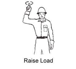
Know and understand the traffic flow patterns of your jobsite. Know all Telescopic Handler hand signals for safety. Utilize signal persons and be sure you can see the signal person and acknowledge the signals given.


When ramps must be used in transporting loads with the machine, the following are the minimum widths for safe travel:
Compacted dirt, gravel, etc.12 ft. (3.6 m)
Woodboard, concrete, etc.10 ft. (3.0 m)
Permanent aisles, roadways and passageways, floors and ramps must be clearly defined or marked. Permanent or temporary protrusion of loads, equipment, material and construction facilities into the usual operating area must be guarded, clearly and distinctively marked, or clearly visible.
Maintain a safe distance from the edge of ramps, platforms and other similar working surfaces.
Controlled lighting of adequate intensity should be provided in operating areas. Where operating conditions dictate, the operator/user is responsible for having the machine equipped with lights.
Provisions must be made to prevent trucks, semi-trailers and railroad cars from being moved during loading and unloading. Wheel stops, parking brakes, or other positive holding means must be used to prevent movement during loading and unloading.
DO NOT move railroad cars and trailers with the Telescopic Handler.


DO NOT use the boom and attachment for leverage to push the machine out of mud.

IMPORTANT: DO NOT lower boom at high engine speed when attachment tool is at maximum rearward tilt. Damage to slave cylinders may result.

General Load Handling


NEVER operate controls except from the operator’s seat. NEVER jerk or use fast movements. Avoid sudden stops, starts and changes in direction.
Operation of the hydraulic system depends on engine speed and the distance the controls are moved. When operating these controls it is important to develop a technique called “feathering.” Feathering the control means starting the desired motion by moving the control a small distance away from neutral. Then after movement has started, the control can be eased to full travel. Use the same feathering technique to slow and stop the motion.
Warning
Excessive speed can be hazardous. ALWAYS exercise caution and good judgement while operating the machine.
ALWAYS maintain a safe distance from electric power lines and avoid contact with any electrically charged conductor and gas line. It is not necessary to make direct contact with a power line for power to ground through the structure of the machine. Keep the boom and load at least 10 ft. (3 m) from all power lines. Accidental contact with a power line or rupture of a gas line can result in electrocution or an explosion. Contact the “Call Before You Dig” referral system number at 8-1-1 in the U.S., or 888-258-0808 in the U.S. and Canada, to locate any underground utility lines BEFORE starting to dig.
Keep all body parts inside the operator’s station while operating the machine. BE SURE of clearance for the attachment tool when turning, working around buildings, etc.
Turning corners too fast can tip the machine, or cause a load to slide off the attachment. Sudden slowing or stopping of the machine may cause the load to drop off the attachment tool.
Be certain you can control both speed and direction before moving. Always place the machine in neutral and set the parking brake before raising or extending the boom. NEVER drive the machine up to someone standing in front of the load.
NEVER leave the operator’s station without first lowering the attachment tool to the ground. Then set the parking brake, place controls in neutral, shut off engine and remove the key. AVOID parking the machine on a slope, but if necessary, park across the slope and block the tires.
Load Capacity and Reach
This machine has flip-charts in the operator’s station that provide, at a glance, the load capacity limits at various positions of attachment tool extension and elevation. A set of the load zone charts is reproduced at the end of this manual for reference.
A typical load zone chart is shown on this page. The scale on the left indicates height in feet above the ground level. The scale on the bottom shows the distance in feet out from the front of the machine. The arc lines noted by the numbers “1” through “5” correspond with the boom extension marks on the operator side of the intermediate boom section.

The following example illustrates proper use of the load zone charts for the Telescopic Handler:
Example: The operator, using a standard carriage attachment tool without outriggers, wants to raise a 4000 lb. load 25 feet high, and can only get to within 15 feet of the load placement point. Can this be done within the capacity of the machine?
Analysis: See “Typical Load Zone Chart” above.
Projecting up from the 15-foot reach mark on the horizontal axis to intersect a line through the 25-foot height mark on the vertical axis shows that a load up to 4000 lb. can be placed in that zone.
During placement, the operator should observe when the boom extension mark number “4” on the boom is visible and stop further extension. The operator knows the maximum safe extension distance with the 4000 lb. load has been reached.
Warning
NEVER exceed the rated operating capacity of the Telescopic Handler as shown on the load zone charts.
Lifting Attachment Tool Applications
Picking Up the Load
Inspect the load. If it appears unstable, DO NOT attempt to move it. DO NOT attempt lifting doubletiered loads, or straddling side-by-side pallets with one on each fork. NEVER add extra unauthorized counterweights to this machine. Consider the additional weight of any attachment tool as part of the picking load capacity of the machine.
Warning
Operating conditions can reduce the machine’s safe operating capacity. Exceeding the capacity when raising or extending the boom will cause the machine to tip forward.
Approach the load slowly and squarely with the machine straight and level. Adjust the space between forks, if necessary. Engage the load equally on both forks until the load touches the carriage backrest. Tilt the forks back to position the load for travel.
Carrying the Load
If the load obstructs your view, get someone to direct you. Maintain ground speeds consistent with ground conditions and that permit stopping in a safe manner.
Warning
NEVER travel with the boom above the carry position (attachment tool should be at minimum ground clearance). Boom should be fully retracted.
Use lower gear when traveling down an incline. NEVER coast with the transmission in neutral. Travel up and down grades slowly.
DO NOT operate the machine on a slope or grade that exceeds 22% or 12o.
Load Elevation and Placement
For ground level load placement, be sure the area under the load and around the machine is clear of equipment and personnel. Lower the load to the ground, tilt the forks to the horizontal position, and then carefully back away to disengage the forks from the load.
For elevated or overhead placement, bring the machine as close as possible to the landing point, and then:
1.Level the machine BEFORE raising the load. Use extreme caution for high placement. Be sure personnel are clear of the area where the load or the machine could fall or tip.
2.Set the parking brake, hold the service brake pedal fully applied and slowly raise the load, maintaining a slight rearward tilt to cradle the load.
3.As the load approaches the desired height, feather the boom control at minimum speed until the load is slightly higher than the landing point.
4.Continuing the feathering technique, lower the load into place.
5.Free the forks from the load by alternately retracting and raising the boom. If this process is not possible, very slowly and carefully reverse the telescopic handler to free the forks from the load.
6.Lower the forks to travel height.
Installation of a Personnel Work Platform (PWP)
Warning
The machine must not be used to lift or carry personnel, or be fitted with any form of personnel work platform unless fitted with the optional PWP System.
If fitted with the PWP System, the Mandatory Work Platform Safety Rules (p. 12) must be adhered to at all times while lifting personnel.
1.Center the forks on the carriage, spaced apart to match the distance required to engage the PWP.
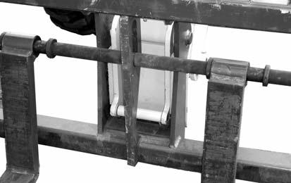
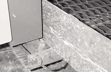
2.After the forks are fully engaged in the PWP, secure the PWP to the forks. This can be accomplished by means of a retaining pin behind the heel of the forks, as shown on the next page.
Warning
The PWP must meet ANSI/ITSDF B56.6-2005, Section 8.24. (See page 13 in the Safety chapter for PWP design requirements.) If the PWP being used does not offer means to secure the PWP to the forks and to secure the forks from pivoting, as shown in steps 2 and 3, then an alternate method must be used.
5.Secure the lanyard from the body harness to the PWP or the boom. Each person in the PWP should have a body harness with a lanyard attached to the PWP.
Elevating Personnel
This Telescopic Handler is primarily intended for use as a material handler. It should only be used to elevate personnel if it is equipped with the (optional) PWP System when there is no other practical option. If this machine is to be used to elevate personnel, then use only an approved work platform, lift personnel only with the PWP System activated, and follow the “Mandatory Work Platform Safety Rules” (p. 12, Safety chapter).
If this Telescopic Handler is equipped with a PWP System and is to be used for elevating personnel, the system must be activated, by the "PWP System" mode switch, which is located in the instrument and switch panel. To activate the system, apply and hold the service brakes on for three or more seconds, and press the top of the PWP rocker switch. The system is activated when the lamp in the PWP rocker switch is on continously.
NOTE: If the light is flashing, apply the service brakes until the light stops flashing.
Warning
ALWAYS check the PWP System for proper operation prior to use. (See page 52 for PWP System checking procedure.)
When the PWP System is active: l transmission is de-clutched into Neutral l parking brake is applied l rear axle stabilizer cylinder is locked l auxiliary hydraulic and carriage tilt and swing functions are disabled l machine inclination sensor is activated, with the result that the Telescopic Handler must be level laterally (side-to-side) and longitudinally (front-to-back) to within the factory preset limits before the boom control joystick will function l remote shutdown switch is activated, with the result that the switch must be connected and in the “on” position for the boom control joystick to function. Depressing the switch will disengage the boom control joystick, and stop all platform movement. The remote shutdown switch box is supplied with a coiled electrical cable that must be connected to the outlet on the front of the innermost boom section near the carriage. The switch must be accessible by the platform personnel any time the platform is to be moved.

To de-activate the system, apply and hold the service brakes on for three or more seconds, and press the bottom of the PWP System rocker switch. The system is de-activated when the lamp in the PWP System rocker switch is off.
NOTE: If the lamp in the PWP system rocker switch is flashing, apply the service brakes until the lamp goes off.
Warning
In an emergency, if the platform worker has activated the remote shut-off switch and then is not able to re-activate the switch, such as if the worker fainted, then the Telescopic Handler operator is permitted to turn off the PWP System to regain control of the boom functions, in order to lower the work platform and come to the aid of the worker. But, understand this is only permitted in case of an emergency. Otherwise, the PWP System must be used at all times when there are workers on the platform. This is the only exception!
Stabilizer System
This is an additional safety function while elevating loads for placement. At a pre-determined angle, the stabilizer cylinder on the rear axle will lock up. When this happens, the parking brake is activated. The machine will not be able to move until the boom is lowered below the pre-determined angle.
Warning
The machine becomes less stable as the load is raised higher.
NEVER use frame leveling to position an elevated load. Always lower the load to the ground and reposition the machine.
If a hydraulic boom circuit hose should break with the boom up, shut down the machine. DO NOT attempt to bring down the boom or make repairs. Call your Gehl dealer immediately.
As lift height increases, depth perception decreases. High elevation placement may require a signal person to guide the operator.
DO NOT ram the lift cylinders to the end of the stroke. The resulting jolt could spill the load.
A jib or truss boom should ONLY be used to lift and place loads when the machine is stationary and the frame is level. Transporting suspended loads must ALWAYS be done slowly and cautiously, with the boom and load as low as possible. Use taglines to restrict loads from swinging, to avoid overturn.
Suspended Loads
The handling of suspended loads by means of a truss boom or other similar device can introduce dynamic forces affecting the stability of the machine that are not considered in the stability criteria of industry test standards. Grades and sudden starts, stops and turns can cause the load to swing and create a hazard.
Guidelines for “Free Rigging / Suspended Loads”
1.DO NOT exceed the rated capacity of the telescopic handler as equipped for handling suspended loads. The weight of the rigging must be included as part of the load.
2.During transport, the length of the rigging between the attachment and load should be as short as possible to reduce booms height and movement. DO NOT raise the load more than 12 inches (305 mm) above the ground, or raise the boom more than 45 degrees.
3.Only lift the load vertically – NEVER drag it horizontally.
4.Use multiple pickup points on the load when possible. Use taglines to restrain the load from swinging and rotating.
5.Start, travel, turn and stop SLOWLY to prevent the load from swinging. DO NOT exceed walking speed.
6.Inspect rigging before use. Rigging must be in good condition and in the U.S. comply with OSHA regulation §1910.184, “Slings,” or §1926.251, “Rigging equipment for material handling.”
7.Rigging equipment attached to the forks must be secured such that it cannot move either sideways or fore and aft. The load center must not exceed 24 inches (610 mm).
8.DO NOT lift the load with anyone on the load, rigging or lift equipment, and NEVER lift the load over personnel.
9.Beware of the wind, which can cause suspended loads to swing, even with taglines.
10.DO NOT attempt to use frame-leveling to compensate for load swing.
Road Travel
For short distance highway travel, attach a SlowMoving Vehicle (SMV) emblem (purchased locally) to the rear of the Telescopic Handler. For highway operation, obtain and install an amber flashing beacon.
NOTE: ALWAYS follow ALL state and local regulations regarding the operation of equipment on or across public highways. Whenever there is an appreciable distance between jobsites, or if driving on public highway is prohibited, transport the machine using a vehicle of appropriate size and capacity.
Transporting Between Jobsites
ALWAYS abide by the following recommended procedures and guidelines when using ramps to load the machine onto (and unload it from) a truck or trailer. Failure to heed can result in damage to equipment and serious personal injury or death!
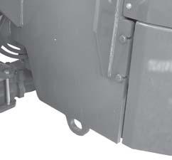
Tie-down eyes are provided for inserting chains through to secure the machine during transport.
1.The ramps MUST be of sufficient strength to support the machine. The use of strong steel ramps is recommended, as well as center supporting blocks.
2.The ramps MUST be firmly attached to the truck or trailer bed with NO step between the bed and the ramps.

Loading Machine Using Ramps
NOTE: A matched pair of ramps is required.
Ramp Placement
3.The incline of the ramps MUST be less than 15 degrees. For a four-foot high truck bed, ramp length must be at least 16 feet (4.9 m) long.
4.Ramp width MUST be at least 1-1/2 times the tire width.
5.Block the front and rear of the tires on the truck or trailer. Engage the parking brake.
6.Position the machine with the boom facing toward the front of the truck or trailer so that it is straight in line with the ramps.
7.Slowly (at the lowest engine speed possible) and carefully drive the machine up the ramps.
8.Secure the machine to the bed of the truck or trailer with tie-down chains/cables.

Unloading Machine Using Ramps
NOTE: A matched pair of ramps is required. Repeat steps 1 through 5 and proceed as follows to unload the machine:
6.Remove the tie-down chains/cables.
7.If necessary, adjust the machine so that the wheels are in line and centered with the ramps.
8.Slowly (at the lowest engine speed possible) and carefully drive the machine down the ramps.
Warning
NEVER adjust travel direction (even slightly) while on the ramps. Instead, back off the ramps, and then realign the machine with the ramps.
Warning
NEVER transport the machine with the boom raised or extended. BE SURE to secure the machine (including boom) to the truck or trailer bed using chain and binders or steel cables, to prevent any movement while transporting.
Theft Deterrents
Gehl Company has recorded all component part numbers and serial numbers. Users should take as many of the following actions as possible to discourage theft, to aid in the recovery of the machine in the event it is stolen, and to reduce vandalism:
1.Remove keys from unattended machines.
2.Attach, secure, and lock all anti-vandalism and anti-theft devices on the machine.
3.Lock doors of cabs when not in use.
4.Inspect the gates and fences of the equipment storage yard. If possible, keep machines in welllighted areas. Ask the local law enforcement agency to make frequent checks around the storage and work sites, especially at night, during weekends, and on holidays.
5.Report any theft to your dealer and insurance company. Provide the model and all serial numbers. Request your dealer to forward this information to Gehl Company.
General Information
Chapter 7 LUBRICATION WARNING
NEVER lubricate or service this unit when any part of the machine is in motion. ALWAYS exercise the MANDATORY SAFETY SHUTDOWN PROCEDURE (p, 8, SAFETY chapter) before lubricating or servicing this equipment.
NOTE: The Maintenance chapter (Chapter 10) in this manual has provisions for recording the dates and hourmeter readings after lubrication or other service has been performed; use those spaces to keep a log for maintaining a current service interval record. Proper routine lubrication is an important factor in preventing excessive part wear and early failure.
Lubricants
The chart on this page lists the locations, temperature ranges and recommended types of lubricants to be used when servicing this machine. Also refer to the separate engine manual for additional information regarding recommended engine lubricants, quantities required and grades.
NOTE: Refer to “Operator Services” in the Service and Storage chapter of this manual for detailed information regarding periodic checking and replenishing of lubricants.
Hydraulic System Reservoir
Use Mobil DTE 15M, or an equivalent that contains anti-rust, anti-foam and anti-oxidation additives and conforms to ISO VG46/VG32. Capacity: 45 gallons (170 Liters)
All Grease Fittings
Use No. 2 lithium-based grease
Engine Crankcase Oil
Ambient TemperatureGrade*
-22°F - 104°F(-30°C - 40°C)SAE 5W-30
-13°F - 104°F(-25°C - 40°C)SAE 10W-30
-13°F - 122°F(-25°C - 50°C)SAE 10W-40
-4°F - 122°F(-20°C - 50°C)SAE 15W-40
*API Service Classification: CJ-4/Cl-4 PLUS/CI-4
*API Service Classification for first 100 hours on new or rebuilt John Deere engines: CE, CD, or CC
Capacity: 15.5 quarts (14.7 Liters)
Diesel Fuel
IMPORTANT: Use only low sulfur (LSD) or ultra low sulfer (ULSD) diesel fuel. Sulfur content of 1000 PPM or below specified to EN590 or ASTM D975 is strongly recommended.
Axle Gear Oil
MobilFluid® 424 (recommended)
API GL4/GL5 80W with Wet Brake Additive (Gehl Wet Brake Additive part number L71456)
Differential Capacity: 15.8 qts. (15 Liters)
Planetary Capacity : 2.6 qts. each (2.5 Liters)
Transmission Oil
Use Multi-ATF Dexron® III or equivalent
Capacity: 24 quarts (23.0 Liters)
Brake System
Uses hydraulic system oil.
Filter Reference Chart Typepart Number
Engine Oil102173
Engine FuelPrimary 105794
Secondary 105795
Air FilterPrimary 105070
Secondary 105071
Hydraulic ReturnL97489
Hydraulic StrainerL49327
Transmission OilL99184
Cab Ventilation211146
Greasing
Refer to the illustrations and listings for fitting locations. Wipe dirt from the fittings before greasing them to prevent contamination. Replace any missing or damaged fittings. To minimize dirt build-up, avoid excessive greasing.
Basic Machine Grease Fitting Locations
Every 50 Hours (or weekly)
Refer to the illustrations on the facing page for locations.
--- BOOM AREA ---
1.Boom-to-frame upright pivot pins (2)
2.Rod end slave cylinder pivot pins (2)
3.Rod end lift cylinder pins (2)
4.Extend cylinder pin
5.Chain sheaves pins, (2)
6.Dynattach-to-boom nose pivot pin
7.Tilt cylinder pivot pins (2)
8.Boom slide pads - as required, front and rear
--- CHASSIS AREA ---
9.Brake pedal linkage
10.Wheel spindle pins (4 per axle)
11.Stabilizer cylinder pivot pins (3)
12.Axle pivot pins (2 per axle)
13.Drive shafts (3 per drive shaft)

14.Leveling cylinder pivot pins (2)
15.Base end lift cylinder pivot pins (2)
16.Base end slave cylinder pivot pins (2)
--- OUTRIGGERS ---
Refer to the illustration below.
17.Outrigger pad (2 per pad)
18.Outrigger cylinder (2 per cylinder)
19.Outrigger leg pivot (1 per leg)


General Information
Chapter 8
Service And Storage Warning
When a problem occurs, do not overlook simple causes such as an empty fuel tank. Check for leaks and broken connections. Make note of any specific symptoms, noises, etc. and contact your local Gehl dealer.
BEFORE performimg any service on the Telescopic Handler, unless expressly instructed to the contrary, exercise the MANDATORY SAFETY SHUTDOWN PROCEDURE (p. 8, Safety chapter). After service has been performed, BE SURE to restore all guards, shields and covers to their original positions BEFORE resuming machine operation.
NOTE: All service routines, with the exception of those described under the “Dealer Services” topic, are owner-operator responsibilities. All operator services described under the subtopics are also referred to on a decal located on the inside right side panel of the operator’s station. Refer to the Lubrication chapter of this manual for lubrication information.
NOTE: This Service and Storage chapter describes procedures to follow for making routine maintenance checks, adjustments and replacements. Most of the procedures are also referred to in the Maintenance chapter of this manual. For engine related adjustments and servicing procedures, refer to the engine manual provided.
Precautions
DO NOT perform any maintenance or repair without the owner’s prior authorization. Allow only trained personnel to service the machine.
Warranty repairs can only be done by an authorized Gehl dealer. Dealers know what portions of the machine are covered under the terms of the Gehl Warranty and what portions are covered by other vendor warranties.
IMPORTANT: Always dispose of waste lubricating oils, anti-freeze and hydraulic fluids according to local regulations or take them to a recycling center for disposal. DO NOT pour them onto the ground or into a drain.
Dealer Services
The following areas of internal components service replacement and operating adjustments should only be by (or under the direction of) an authorized Gehl Telescopic Handler dealer.
IMPORTANT: DO NOT service or repair major components, unless authorized to do so by your Gehl dealer. Any unauthorized repair will void the warranty.
Power Train Components
The engine and transmission are coupled directly to each other. All service routines related to the internal components are precise and critical to proper power train operation. The axle differential and planetary ends are also sophisticated assemblies that require special know-how and tools for servicing.
IMPORTANT: If any powertrain components are suspected of faulty operation, contact your Gehl dealer for assistance.
Hydraulic System Components
Valves, pumps, motors and cylinders are also sophisticated assemblies which require special know-how and tools for servicing. All cylinders are appropriately designed with particular strokes, diameters, checks and hose connection provisions unique to the machine application requirements. A schematic (Maintenance chapter) can be used as a guide for service reference, as required.
Warning
Tilt, lift, extend and leveling cylinders have counterbalance valves. These valves keep hydraulic fluid from entering and exiting the cylinders while they are not being activated, and they are under extremely high pressure. Before removing one of these valves, you ARE REQUIRED to call your Gehl dealer or Gehl Service Department. Failure to do so may result in serious injury or death.
Internal service on any of these components should only be performed by (or under the direction of) an authorized Gehl Telescopic Handler dealer.
Electrical Components
An electrical system schematic is provided, which includes instrumentation, electrical components and switch connections. It is located at the back of this manual and can be used as a guide for service reference, as required.
Operator Services
Some of the operator-related services will require access to components located inside the superstructure, under shields, hoods and covers. The chart on this page notes the components accessed in each particular area.
Access To Components Chart
Warning
DO NOT smoke or allow any open flames in the area while checking or servicing hydraulic, battery or fuel systems; all contain highly flammable liquids or explosive gases, which can cause an explosion or fire if ignited. Wear a face shield when disassembling spring-loaded components or working with battery acid. Wear a helmet or goggles with special lenses when welding or cutting with a torch.
When working beneath a raised machine, always use blocks, jack-stands or other rigid and stable supports. Wear appropriate protective clothing, gloves, and shoes. Keep feet, clothing, hands and hair away from moving parts.
Always wear safety glasses or goggles for eye protection from electric arcs from shorts, fluids under pressure, and flying debris or loose material when the engine is running or tools are used for grinding or pounding.
NEVER weld on bucket, forks, boom, support frame or ROPS/FOPS without the consent of the manufacturer. These components may be made with metals that require special welding techniques, or with designs that do not allow weld repairs. NEVER cut or weld on fuel lines or tanks.
If repair welding is ever required, BE SURE to attach the ground (-) cable from the welder as close as possible to the area to be repaired. Also, remove battery positive (+) terminal connection before welding.
Choose a clean, level work area. Make sure you have sufficient room, clearances, and adequate ventilation. Clean the walking and working surfaces. Remove oil, grease and water to eliminate slippery areas. Utilize sand or oil absorbing compound, as necessary, while servicing the Telescopic Handler.
Before starting inspection and repair, move the machine onto a level surface, shut down engine, and release all hydraulic pressure. Always block the boom securely, or lower it to full ground contact. Place all controls in neutral.
Block the wheels. Remove the ignition key. Remove only guards or covers necessary to provide needed access. Wipe away excess grease and oil.
Excessively worn or damaged parts can fail and cause injury or death. Replace any cracked or damaged parts. Use only genuine Gehl parts for service.
Use care not to damage machined and polished surfaces. Clean or replace all damaged or painted-over plates and decals that cannot be read.
Warning
NEVER leave guards off or access doors open when the machine is unattended. Keep bystanders away if access doors are open.
After servicing, check the work performed, that no parts are left over, etc. Install all guards and covers.
Service Every 10 Hours or Daily
Checking Fuel Tank Level
The fuel level is shown by the fuel level gauge on the instrument panel. After operation each day, the fuel tank should be filled to prevent water from condensing in the tank. To fill, remove the filler cap and add fuel. See the Lubrication chapter for the diesel fuel requirements.
Checking Engine Oil Level
With the machine on level ground, and the engine stopped for ten minutes or more, slide open the side engine panel and remove the engine dipstick. Wipe it clean, re-insert it and remove to obtain a reading. If the oil level is below the crosshatch pattern on the dipstick, fill with the required amount of oil to bring the level to within the crosshatch pattern. Oil levels anywhere within the crosshatch are considerred full. See the Lubrication chapter for the type of oil to use.
Checking Radiator Coolant Level
With the machine on level ground, remove the radiator cap. If the coolant level is below the filler neck, add a low-silicate ethylene glycol based coolant mixed with quality water and supplemental coolant additives (SCAs) suitable for heavy duty diesel engines. See the engine manual for additional information. Replace the radiator cap securely.
Warning
DO NOT remove the radiator cap when the engine is running hot or overheated. Coolant is extremely hot and under pressure and it can burn your skin. Allow sufficient time for the radiator to cool BEFORE relieving the pressure and removing the radiator cap.
NOTE: If the engine is operated with a loose radiator cap, the pressure bypass will not work and the engine will run hot.
Checking Transmission Oil Level
The machine must be on level ground. With the engine and transmission at operating temperature, parking brake on, transmission in neutral and engine speed at low idle, remove the access cover to the transmission and hydraulic pump. Remove the dipstick and check the oil level. Add the required amount of oil to bring the level to the FULL mark. See the Lubrication chapter for the type of oil to use.
Checking Hydraulic Oil Level
The machine must be on level ground with boom lowered and completely retracted. The fluid MUST be cool when checking the reservoir level, to reduce the possibility of overfilling the hydraulic system.
Visually check the level of the hydraulic oil through the sight gauge located on the right side of the front hood. If low, remove the access cover from the front hood to replenish the oil through the filler cap. See the Lubrication chapter for the type of oil to use.
IMPORTANT: Be careful when removing the reservoir filler cap so that no dirt or other foreign matter enters the hydraulic system. DO NOT OVERFILL.
Checking Tire Pressures
To ensure proper operating stability and extend tire life, proper and equal tire pressure should be maintained in all four tires.
Check tire pressures “cold.” Inflate as necessary per the chart below: 13.00 x 24 - 12
65 psi (450 kPa)
62 psi (430 kPa)
70 psi (480 kPa)
NOTE: If the tires have been filled with water or calcium chloride for ballast, a calcium chloride tire pressure gauge MUST be used to check the tire pressure.
To ensure proper load carrying capability, original equipment tires comply with the specifications published in the Tire and Rim Association Yearbook. Replacement tires MUST meet the same specifications. When replacing tires, be sure all tires are of the same type, quality and load rating, and the same size as the original equipment. When removing tires, follow industry safety practices. Deflate completely prior to removal. After assembly of the tire on the rim, use a safety cage or restraining device while inflating.
Warning
Inflating or servicing tires can be dangerous. Whenever possible, trained personnel should service and mount tires. To avoid possible death or serious injury, follow the safety precautions below:
1.BE SURE the rim is clean and free of rust.
2.Lubricate both the tire beads and rim flanges with a soap solution. DO NOT use oil or grease.
3.DO NOT place fingers on the tire bead or rim during inflation. Use a clip-on tire chuck with a remote hose and gauge, which allows standing clear of the tire while inflating it.
4. NEVER inflate beyond 35 psi (240 kPa) to seat the beads. If the beads have NOT seated by the time the pressure reaches 35 psi (240 kPa), deflate the assembly, reposition the tire on the rim, relubricate both parts and re-inflate. Inflation pressure beyond 35 psi (240 kPa) with unseated beads may break the bead or rim with explosive force sufficient to cause death or serious injury.
5.After seating the beads, adjust the inflation pressure to the recommended operating pressure listed.
6.DO NOT weld, braze, or otherwise attempt to repair and use a damaged rim.
Checking Wheel Nut Torque
On new machines, or any time a wheel has been removed, re-torque until 450 ft.-lbs. (610 Nm) is maintained.
Checking Instruments Operation
Allow the engine to warm up for about five minutes before beginning operation. Indicator lamps should be OFF and gauges should register normal readings. Tilt the frame from side to side with the frame leveling control and note the angle indicator movement.
Checking General Machine Operation And Condition
Are any decals missing or damaged? Are all guards, shields and covers in place? Do all controls function smoothly and properly? Are there any abnormal vibrations or noises? Are any hose or fitting connections leaking? Is the engine exhaust color normal?
CHECKING PERSONNEL WORK PLATFORM (PWP) SYSTEM (if used)
Warning
If the PWP System fails to operate properly during any of the PWP System checks, DO NOT USE the machine until the cause has been corrected. Contact your dealer (or Gehl Company) for service information and parts.
Machine Position
The following must be performed before begining the PWP System checking procedures:
1.Machine on level surface,
2.Boom fully lowered,
3.Frame level,
4.Transmission in “N” (Neutral),
5.Parking brake switch “OFF,”
6.PWP System switch “OFF,”
7.Remote switch plugged in and “ENGAGED.”
Activation Tests
To test the PWP System activation logic:
1.Start the engine and press the PWP rocker switch to “ON.” l The PWP System lamp in the switch should be flashing. l The PWP switch lamp should be illuminated continuously after three seconds, indicating that the PWP System has been activated. l The parking brake should engage, as indicated by the lamp in the parking brake switch illuminating. l The carriage tilt and auxiliary functions should now be disabled. The joystick control should continue to function normally for boom raise/lower and extend/retract.
2.Apply the service brakes.
Lockout Tests
To test the transmission and joystick control lockout logic: l The transmission should remain de-clutched, allowing the engine to increase speed easily. l Return the transmission selector to “N” (Neutral) after the check.
1.Shift transmission into “F” (Forward) and increase the engine speed slightly.
2.Have an assistant move the remote shutdown switch to “Dis-engaged.” l The joystick control should now be disabled, so that boom raise/lower and extend/retract will no longer function. l Have the assistant move the remote shutdown switch to “Engaged” after the check. l The joystick control should now be disabled so that boom raise/lower and extend/retract no longer function. l Repeat the procedure with the frame tilted to the left. l Return the frame to a level position after the checks.
3.Tilt the frame to the right slightly more than two degrees.
De-activation Tests
To test the PWP System de-activation logic:
1.Turn the key switch to “OFF” and wait for the engine to stop. Then turn the key switch back to “ON.” l The PWP switch lamp and the parking brake switch lamp should both be illuminated.
2.Turn the key switch to “OFF” and then turn the PWP rocker switch to “OFF.” Turn the key switch back to “ON.” l The PWP switch lamp should be flashing and the parking brake switch lamp should be on continuously. l The PWP switch lamp and the parking brake switch lamp should go off after approximately three seconds of brake pedal application. If PWP System fails to perform properly, troubleshoot using the chart on page 63. Contact your dealer for service information and parts.
3.Start the engine and apply the service brakes.
B
D
Service C d.When fuel starts to drain out, tighten drain plugs securely. e.Reconnect water sensor wire.
Every 50 Hours or Weekly B A
After draining water from the fuel filters, the filters must be primed by bleeding all air from the fuel system. Refer to the fuel bleeding procedure on page 55.
Lubricate Grease Points
Refer to the Lubrication chapter of this manual for grease fitting locations and other related details.
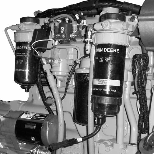
Checking Fuel Filter
Check the fuel filters (C) and (D) for water or debris. If filter is fitted with a see-through bowl, drain as needed based on a daily visual inspection.
IMPORTANT: Drain water into a suitable container and dispose of properly.
a.Disconnect water sensor wire from drain plug (A) on fuel filter (C).
b.Loosen two or three turns drain plugs (A) at bottom of fuel filters or bowls.
c.Loosen air bleed plug (B) two full turns on fuel filter mounting and drain water from bottom until fuel starts to drain out.
A drain plug is also provided in the bottom of the fuel tank for removing condensation and other foreign materials. Open the plug and allow water and fuel to drain into a container until only clear fuel is flowing from the tank.
100 Hours (New Machine Only)
The following initial oil and filter changes should be made at 100 hours on a new machine. Thereafter these changes should be made at the regular maintenance schedule listed below. Refer to those schedules for the necessary procedures.
Engine Oil and Filter (250 Hours)
Transmission Oil and Filter(1000 Hours)
Hydraulic Return Filter Element(1000 Hours)
NOTE: Perform all other service requirements up to this point, as well as the following:
Checking Axle Oil Levels
Differential
NOTE: The Telescopic Handler should be on a level surface for this procedure.
Remove the oil check plug. See illustration below. Oil should flow from the hole. If low, remove the oil fill plug and add oil until it flows from the check hole. Replace the plug, wait 10 to 15 minutes and repeat the fill procedure. Continue this process until the differential is full. See the Lubrication chapter for the proper oil specification. Replace the check and fill plugs.
Changing Fuel Filter
The frequency of filter replacement will be determined by the cleanliness of available fuel, the care used in storing fuel supplies and the operating conditions in which the machine is used.
Warning
NEVER service the fuel system while smoking, while near an open flame, or after the engine has been operated and is hot.
1.Thoroughly clean fuel filter assemblies and surrounding areas.
2.Disconnect water sensor wiring from the filter (F).
3.Loosen drain plugs (C) and drain fuel into a suitable container.
4.Firmly grasp the retaining ring (A) and rotate it clockwise 1/4 turn (when viewed from the top). Remove the ring with filter element (B or F).
NOTE: Lifting up on retaining ring (A) as it is rotated helps to get it past raised locators.
5.Inspect filter mounting base for cleanliness. Clean as required.
Planetary Hubs
NOTE: The planetary hubs can be checked without jacking up the machine.
The planetary hubs have one plug each used for filling and draining. See illustration below. For checking the level and filling, position the wheel until the oil level arrow is horizontal. Remove the plug. If oil does not run out, add oil until it overflows. Check the remaining hubs the same way. Refer to the oil specifications found in the Lubrication chapter of this manual.

NOTE: Raised locators on the fuel filter canister must be indexed properly with slots in mounting base for correct installation.

6.Install new filter elements onto mounting bases. Be sure elements are properly indexed and firmly seated on bases. It may be necessary to rotate filters for correct alignment.

If equipped with water seperator bowl (E), remove filter element from seperator bowl. Drain and clean the separator bowl. Dry with compressed air. Install bowl onto new element. Tighten securely.
7.Align keys on filter element with slots in filter base.
8.Install retaining ring onto mounting base making certain dust seal is in place on filter base. Handtighten ring counter-clockwise (about 1/3 turn) until it snap into the detent. DO NOT overtighten retaining ring.
NOTE: The proper installation is indicated when a “click” is heard and a release of the retaining ring is felt.
9.Reconnect water sensor wiring on the filter (F). After fuel filter replacement, bleed the air out of the fuel system by following the fuel bleeding procedure below.
Fuel Bleeding Procedure
When the fuel filter is removed and replaced, or if the engine runs out of fuel, air must be bled from the system. Refer to the following procedure for proper bleeding procedure.

1.Loosen the air bleed vent screw (D) two full turns by hand on the filter base.
2.Operate the fuel supply pump primer lever (G) until fuel flows out of the bleed vent screw.

3.Tighten bleed vent screw securely. Continue operating the primer until pumping action is not felt.
4.Start engine and check for leaks.
Warning
Escaping diesel fuel under pressure can have sufficient force to penetrate the skin. Before applying pressure to the fuel system, BE SURE all connections are tight and lines and hoses are not damaged. Use a piece of wood or cardboard to search for suspected leaks. If injured by escaping fuel, see a doctor familiar with this type of injury at once or gangrene may result.
If the engine will not start, repeat steps 1-4.
Diesel Fuel Injectors
Whenever faulty or plugged injectors are indicated, see your authorized engine dealer.
Diesel Injection Pump Timing
Whenever injection pump timing, or other pump service is indicated by abnormal engine operation, contact your authorized engine dealer.
NOTE: Only an authorized engine dealer can perform warranty service on the engine.
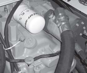
Changing Engine Oil And Filter
Change the engine oil and filter using the following procedure:
1.With the engine warm, remove the crankcase drain plug.
IMPORTANT: DO NOT discharge oil onto ground. Catch and dispose of per local waste disposal regulations.
2.The engine oil filter should be changed at every oil change interval. Using a suitable filter wrench, remove and discard the filter.
IMPORTANT: Filtration of oils is critical to proper lubrication. Always change the filter with every oil change.
3.Apply a thin coat of clean engine oil to the new oil filter at the inner (A) and outer (B) seals and to the filter threads.
4.Wipe both sealing surfaces of the filter header (C, D) with a clean cloth. Ensure keys in the dust seal (E) are properly installed in the slots in the housing. Replace dust seal if damaged.
5.Install and tighten oil filter by hand until firmly against dust seal (E). DO NOT apply an extra 3/4 to 1-1/4 turn after gasket contact is made, as is done with standard filters.
6.Clean and re-install the drain plug.
7.Re-fill the crankcase with new oil. Follow specifications in the Lubrication chapter for type and viscosity of new oil.
8.After new oil has been added, run the engine at idle speed until the oil pressure lamp is off. Check for leaks at the filter and drain plug.
Checking The Battery
The battery furnished in the machine is a 12-volt, wetcell battery.
The top of the battery must always be kept clean. Clean the battery with a brush dipped in an alkaline solution (ammonia or baking soda and water). After the foaming has stopped, flush the top of the battery with clean water. If the terminals and cable connection clamps are corroded or have a buildup, disconnect the cables and clean the terminals and clamps with the same alkaline solution.
Warning
Explosive gas is produced while a battery is in use or being charged. Keep flames or sparks away from the battery area. Make sure battery is charged in a well-ventilated area.
NEVER lay a metal object on top of a battery as a short circuit can result.
Battery acid is harmful on contact with skin or fabrics. If acid spills, follow these first aid tips:
1.IMMEDIATELY remove any clothing on which acid spilled.
2.If acid contacted the skin, rinse the affected area with running water for 10 to 15 minutes.
3.If acid came in contact with the eyes, flood the eyes with running water for 10 to 15 minutes. See a doctor at once. NEVER use any medication or eye drops unless prescribed by the doctor.
4.To neutralize acid spilled on the floor, use one of the following mixtures: a.1 pound (0.5 kg) of baking soda in 4 quarts (4 liters) of water. b.1 pint (0.4 liters) of household ammonia in 4 quarts (4 liters) of water.
Whenever battery is removed from the unit, BE SURE to disconnect the negative (-) battery terminal connection first.
Jump Starting
If the battery becomes discharged or does not have enough power to start the engine, use jumper cables and the following procedure to jump-start the engine.
IMPORTANT: BE SURE that the jumper battery is also a 12-volt D. C. battery, and the vehicle used for jump starting has a negative-ground electrical system.
Warning
The ONLY safe method for jump-starting a discharged battery is for TWO PEOPLE to perform the following procedure. The second person is needed for removing the jumper cables so that the operator does not have to leave the operator’s compartment while the engine is running. NEVER connect the jumper cables directly to the starter solenoid of either engine. DO NOT start the engine from any position other than the operator’s seat, and then ONLY after making sure all controls are in “neutral.”
Closely follow the jump-start procedures, in the order listed, to avoid personal injury. In addition, wear safety glasses to protect your eyes, and avoid leaning over the batteries while jump-starting.
DO NOT attempt to jump-start the machine if the battery is frozen, because this may cause it to rupture or explode.
1.Turn the key switches on both vehicles to “OFF.” Be sure that both vehicles are in “Neutral” and NOT touching.
2.Connect one end of the (red) positive (+) jumper cable to the positive (+) battery terminal on the disabled machine first. DO NOT allow the positive (+) jumper cable clamps to touch any metal other than the positive (+) battery terminals. Connect the other end of the positive jumper cable to the jumper battery positive (+) terminal.
3.Connect one end of the (black) negative (-) jumper cable to the jumper battery negative (-) terminal.
4.Make the final negative (-) jumper cable connection to the disabled machine’s engine block or frame (ground) NOT to the disabled machines negative battery post. If making the connection to the engine, keep the jumper cable clamp away from the battery, fuel lines, and moving parts.
NOTE: Twist the jumper cable clamps on the battery terminals to ensure a good electrical connection.
5.Start the engine. If it does not start immediately, start the jumper vehicles engine to avoid excessive drain on the booster battery.
6.After the machine has started and is running smoothly, have the second person remove the jumper cables (negative (-) jumper cable first) from the jumper vehicle battery, and then from the disabled machine, while ensuring NOT to short the two cables together.
Allow sufficient time for the alternator to build up a charge in the battery before operating the machine or shutting off the engine.
NOTE: If the battery frequently becomes discharged, have the battery checked for possible dead cell(s), or troubleshoot the electrical system for possible short circuits or damaged wire insulation.
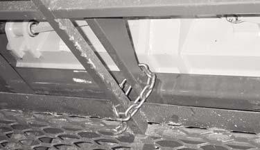
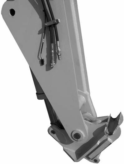
Checking And Torquing Boom Leaf Chains
Inspect the leaf chains for wear and proper tension. Two of the chains are on the top front of the boom. A third chain is accessible from inside the rear of the boom (see “Chain Hook Detail” illustration).

Torque the two chains on the front of the three-section boom to 30 ft.-lbs. (40 Nm). Lubricate with 80W-90 oil.
IMPORTANT: On new machines or when chains have been replaced, it is necessary to retorque the front double chain assembly after one hundred (100) hours of operation. Failure to do so may allow the chains to become slack, which can result in a chain jumping off a sheave. If this occurs, it could result in severe damage to the boom assembly.
Inspect the leaf chains for wear. Run the boom out slowly to inspect. Conditions to look for include: cracked or broken plates, protruding or turned pins, and excessive wear. With a steel tape, measure 16 links of the strand that flexes over the sheaves. If the section measures 12.375” (314 mm) or more, the chain should be replaced. DO NOT repair sections of a chain. Replace the complete chain.
Chain anchors and sheaves also require inspection, for worn or broken fingers and worn flanges.
After any chain has been replaced, operate under loaded conditions and re-check the torque. Adjust the chains per the following procedure: Extend the boom to its maximum length, then retract the boom slowly until the chain slack allows the chain to rest on the top of the boom. Torque the two chains on the front of the boom to 30 ft.-lbs. (40 Nm). Lubricate with 80W-90 oil.
Checking Boom Slide Pad Wear And Clearance
The boom is equipped with special nylon low-friction slide pads between the telescopic sections (see “Typical Slide Pad Detail” illustration). These are pregreased and initially worn in at the factory. Normally greasing is not required, except for maintaining a light film of grease on the pad tracking areas of the boom sections. An exception would be if a boom section has been replaced.
Visually check for loose pad bolts. The bolts are torqued to 30 ft.-lbs. (40 Nm). If the bolts are retorqued at any time, Loctite® thread lock must be reapplied to the bolts.
If the boom starts to chatter under load, grease the slide pads and wipe off the excess grease. Maintain a clearance of 1/16” between the top or side slide pads and the boom. Shims can be added to achieve the proper clearance. Loosen the bolts and insert shims until proper clearance is obtained.

NOTE: When inserting shims in the side slide pads, be sure to place equal shims on both sides of the boom for even distribution of clearance.
Re-apply Loctite® thread lock to the bolts and retorque to 30 ft.-lbs. (40 Nm). Bottom slide pads should not be shimmed and should be replaced when the thickness is worn down to 3/8” (9.5 mm).
Failure to maintain proper slide pad clearance and thickness could cause damage to the boom, resulting in sudden boom failure.
Clean Air Conditioning Condenser
NOTE: Clean the condenser more often if there is a noticeable decrease in A/C performance.
IMPORTANT: Do not use a water jet or high-pressure steam, because this could damage the fins.

1.Remove the six screws (1) from the top cover of the condenser.
2. Remove the cover to gain access to the condenser (2).
3.Clean any large debris that may have collect on the top side of the condenser.
4.Clean the condenser use a jet of compressed air aimed in the same direction as the air flow.
NOTE: To aid in the cleaning process, carry out this operation with the condenser fans running.
5.Re-install the top cover.
CLEAN/CHANGE CAB VENTILATION FILTER
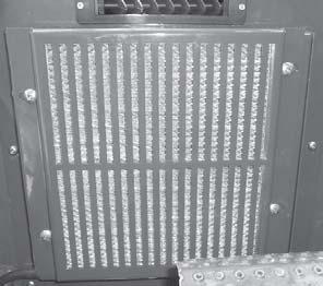
NOTE: Clean or change the filter more often if there is a noticeable decrease in air flow from the air vents.

1.Remove the four screws (1) from the filter protective cover located on the lower portion of the dash in front of the brake pedal.
2. Remove the filter from the cover.
3.Clean the filter with a jet of compressed air.
4.Check the condition of the filter and replace it if neccessary.
5.Install the filter in the protective cover, then reinstall the protective cover.
Service Every 1000 Hours or Yearly
NOTE: Perform all other service requirements up to this point, as well as the following:
Changing Transmission Oil And Filter
Operate the machine long enough to warm the transmission oil to 150°-200°F (65°-93°C). Shut off the engine. Access to filter is from under the access cover on the front hood section. Access to the drain plug is from underneath the machine. Proceed as follows:
IMPORTANT: DO NOT OVERFILL! lf the oil level is too high, oil foaming, excessively high oil temperature and oil leakage at the seals could result.
4.Start and run the machine long enough for the oil to circulate and warm slightly. Recheck the level with the dipstick.
Changing Radiator Coolant
Drain, flush and refill the cooling system as follows:
IMPORTANT: DO NOT discharge coolant onto ground. Catch and dispose of per local waste disposal regulations.
Warning
Remove the radiator cap only when the engine is cool, or painful burns could result.
Transmission Drain Plug
1.Remove the drain plug and drain old oil. Replace the drain plug.

IMPORTANT: DO NOT discharge oil onto ground. Catch and dispose of per local waste disposal regulations.
2.Remove and discard the oil filter. Wipe the sealing surface on the transmission with a clean cloth. Apply a thin coat of clean oil to the new oil filter gasket. Hand tighten.
3.Refill the transmission with new oil as listed in the Lubrication chapter of this manual.
Transmission Filter
Transmission Dipstick and Filler
1.Loosen the radiator cap to its stop. This will release any system pressure. Remove the cap when all pressure is bled off.
2.Open the radiator drain cock. Remove the water jacket drain plugs from the engine block. When all coolant is drained, flush the system with clean fresh water. Allow the flush water to drain completely.
3.Replace the drain plugs and tighten the radiator drain cock. Clean the cooling fins in the radiator with water pressure or steam.
IMPORTANT: Fill the cooling system with a lowsilicate ethylene glycol based coolant mixed with quality water and supplemental coolant additives (SCAs) suitable for heavy-duty diesel engines. See the engine manual for additional information.
4.Inspect the radiator cap seal before installing it. Replace it if it appears to be damaged. The pressure cap and engine thermostat work in conjunction with each other to maintain proper engine cooling.
NOTE: Check the engine temperature gauge every minute or two after coolant has been changed. Air pockets can form and it may be necessary to refill the cooling system after a short period of use, as the air will naturally bleed out of the system.
Changing Hydraulic Return Filter Element
Warning
When servicing the hydraulic system, lower the boom to the ground.
This element is a cartridge-type accessible from a housing on top of the hydraulic reservoir. Initial replacement is after the first 100 hours. See illustration. Remove the top cover of the housing. Remove the element and discard. Insert the new element into the housing and replace the cover.
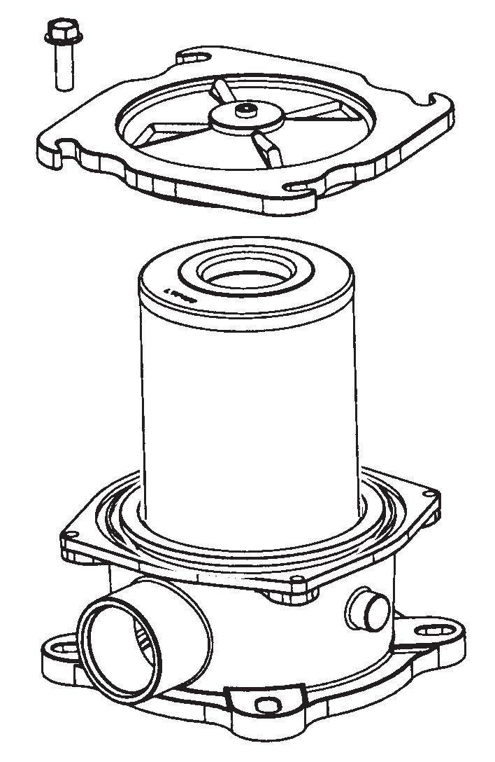
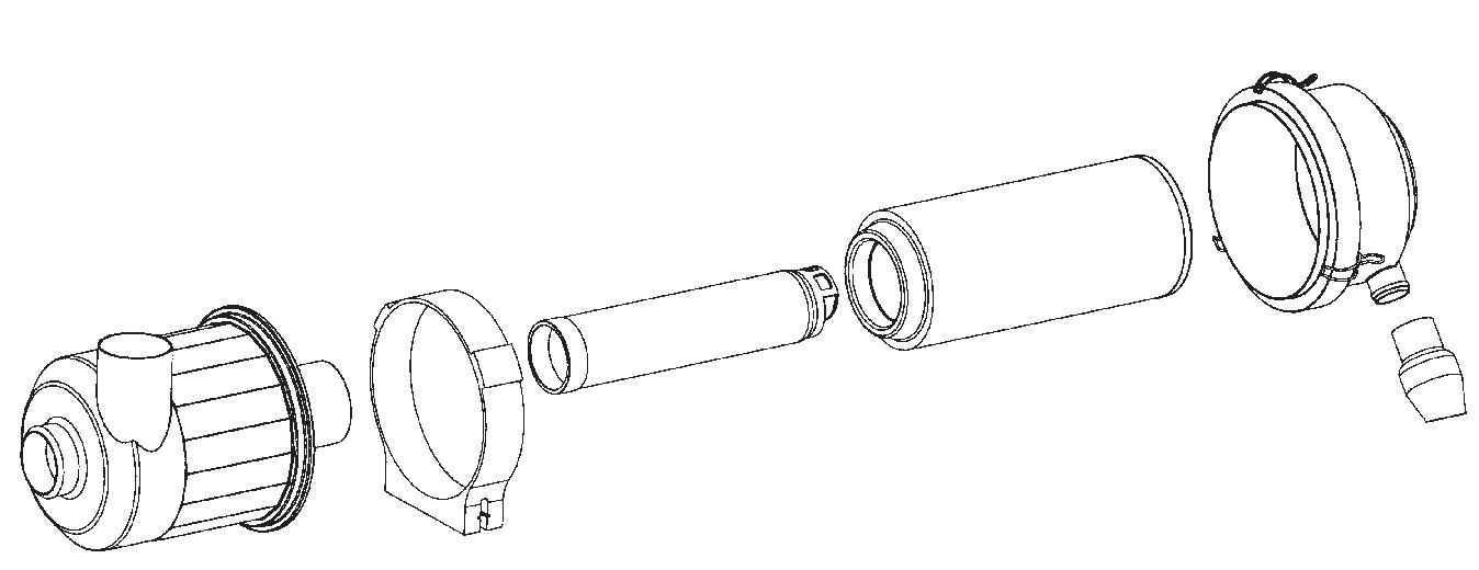
Unlatch the three latches on the air cleaner and remove the end cap assembly. Clean out any dirt built up in the end cap assembly.
Primary Element
1.Carefully pull the primary (outer) element out of the housing. Never remove the secondary (inner) element unless it is to be replaced.
2.Clean out any dirt built up in the housing. Leave the secondary element installed during this step to prevent debris from entering the engine intake manifold.
3.Use a trouble light inside the primary element to inspect for bad spots, pinholes and ruptures. Replace the primary element if any damage is noted. The primary element must be replaced if it is oil- or soot-laden.
CHANGING AIR FILTER ELEMENT(S)
The air cleaner assembly consists of an outer (primary) filter element and an inner (secondary) filter element. An air filter restriction indicator for monitoring the condition of the elements is located on the front of the air cleaner. If the air filter becomes restricted, this indicator turns red to warn the operator that the air cleaner requires service. Push the reset button located at the end of the indicator after fitting a clean element.
NOTE: Before replacing the filter element(s), push the reset button on the indicator. Start the engine and run at full throttle. If the indicator does not turn red, do not replace the element(s).
The outer element should be replaced only when the restriction indicator turns red. The inner element should be replaced every third time the outer element is replaced, unless the outer element is damaged or the inner element is visibly dirty. Along with a daily check of the restriction indicator, check that the air cleaner intake hose and clamps, and the mounting bracket hardware are properly secure.
NOTE: Cleaning the primary element is not recommend.
Secondary Element
NOTE: Replace the secondary element only if it is visibly dirty or if the primary element has been replaced three times.
Before removing the secondary element from the housing, clean out any dirt built up in the housing. Leave the secondary element installed during this step to prevent debris from entering the engine intake manifold. Remove the secondary element.
Reinstallation
1.Check the inside of the housing for any damage that may interfere with the elements.
2.Be sure that the element sealing surfaces are clean.
3.Insert the element(s), making sure that they are seated properly.
4.Secure the end cap to the housing with the three latches.
5.Check the hose connections and make sure they are all clamped and tightened properly.
6.Reset the restriction indicator by pressing the reset button.
Changing Axle Differential And Planetary Oil
Differentials
1.Remove the three drain plugs and drain the used oil. Replace the drain plugs (see illustration).
IMPORTANT: DO NOT discharge oil onto ground. Catch and dispose of per local waste disposal regulations.
2.Re-position the hub so the oil level arrow is horizontal. Fill with fresh oil as specified in the Lubrication chapter. When the oil runs out, install the drain/fill plug.
Repeat this procedure on the three remaining hubs.
Checking Alternator And Fan Belt Condition
Refer to the engine manual for proper fan belt tension adjustment and replacement procedures. If the belt shows wear or cuts, it should be replaced. Order a replacement belt from your Gehl dealer.
Checking Exhaust System
Examine the muffler and tail pipe for possible holes. Re-tighten any loose clamps and make sure the manifold outlet gasket is not leaking.
IMPORTANT: DO NOT discharge oil onto ground. Catch and dispose of per local waste disposal regulations.
2.Remove the fill/check plug. Fill the differential with fresh oil as specified in the Lubrication chapter. When the oil flows from the check hole, replace the plug. Wait 10 to 15 minutes and repeat this process until the axle is full. Repeat this procedure with the other axle.
Axle Planetary Hubs
The hubs have one plug each used for draining and filling (see illustration)
NOTE: Perform all other service requirements up to this point, as well as the following:
Checking Hydraulic System
RELIEF PRESSURES
Pressure settings for relief valves are pre-set at the factory. Three test ports are provided under the front hood access cover.
1.Position the wheel until the oil level arrow points down. Remove the drain/fill plug and allow the oil to drain. Replace the plug.
Before conducting any test port pressure checks, check the engine speed. Engine speed must be 800 rpm at low idle and 2500 to 2550 rpm at high idle.
Steering Relief Pressure
Plug a 3000 psi (207 bar) oil-or liquid-filled gauge into the test port labeled ”SP.” Cramp the steering fully to the right or left. The gauge should read 2500 psi (172 bar).
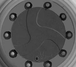
Joystick and Parking Brake Release Pressure
Plug a 1000 psi (70 bar) gauge into the port labeled “JP.” With the engine running, the gauge should read 350 psi (24 bar).
Main Relief Pressure
Plug a 3000 psi (207 bar) oil-or liquid-filled gauge into the test port labeled “MP.” Fully retract the boom over the relief valve. The gauge should read 3000 psi (207 bar).
Changing Hydraulic Reservoir Oil And Strainer
Clean all dirt and debris from around the top of the reservoir, especially around the access cover. Refer to illustration and use the following procedure:
4.Fill the reservoir with fresh oil. Follow specifications in the Lubrication chapter of this manual.
IMPORTANT: Hydraulic fluid and filters should be replaced any time contamination is present before the normally scheduled change.
Warning
NEVER use your hands to search for hydraulic fluid leaks. Escaping hydraulic oil under pressure can have sufficient force to penetrate the skin. Before applying pressure to the hydraulic system, be sure all connections are tight and lines and hoses are not damaged. Use a piece of wood or cardboard to search for suspected leaks. If injured by escaping hydraulic oil, see a doctor familiar with this type of injury at once or gangrene may result.
Storage
If the Telescopic Handler will not be operated for a period of three months or more, prepare and store it using the following procedure:
NOTE: If the storage area is outdoors or in a harsh environment, the storage procedure should be followed if the Telescopic Handler is to be stored for one month.
Before Storage
Perform the following prior to placing the machine in storage:
1Wash the entire machine.
1.Remove the drain plug and drain used oil. Wash or blow off all particles collected on the magnetic drain plug.
IMPORTANT: DO NOT discharge oil onto ground. Catch and dispose of per local waste disposal regulations.
2.Remove the access cover and wash the inlet screen with clean solvent. Remove and wash the sump filter strainer from the bottom inside of the reservoir. If the strainer has any damage, holes, etc., it should be replaced.
3.Flush out the bottom of the reservoir with clean hydraulic oil. Re-install all cleaned components and install the access cover on the reservoir with a new gasket. Clean the filter/breather cap.
2.Lubricate all grease fittings as described in the Lubrication chapter of this manual.

3.Change engine oil as outlined in the Service and Storage chapter of this manual.
4.Apply grease to all exposed hydraulic cylinder rod areas.
5.Disconnect the battery cable clamps and cover the battery or remove the battery from the machine and store it separately.
6.If the ambient temperature (at any time during the storage period) is expected to drop below freezing, make sure the engine coolant is either completely drained from the radiator and engine block or that the concentration of anti-freeze is adequate to keep the coolant from freezing. Refer to the separate engine manual provided for anti-freeze recommendations and quantities.
During Storage
1.About once each month, connect the battery, check all fluid levels to make sure they are proper, and start the engine.
IMPORTANT: If it is desired to operate the hydraulic cylinders at this time, BE SURE to wipe the protective grease (and any adhering dirt) from the cylinder rods prior to starting the engine. After operating, BE SURE to recoat the cylinder rods with grease if the machine is to be returned to storage.
2.Allow the engine to run until it warms up and then move the machine a short distance to help relubricate the internal parts. Run the engine until the battery is recharged and then shut it off.
After Storage
After removing the machine from storage and BEFORE operating it, perform the following:
1.Change engine oil and filter to remove condensation and other residues.
2.Wipe off grease from cylinder rods.
3.Lubricate ALL grease fittings.
4.Follow the start-up and warm-up procedures outlined in the Operation and Adjustments chapter of this manual.