3 minute read
Indicator and Operation Symbols


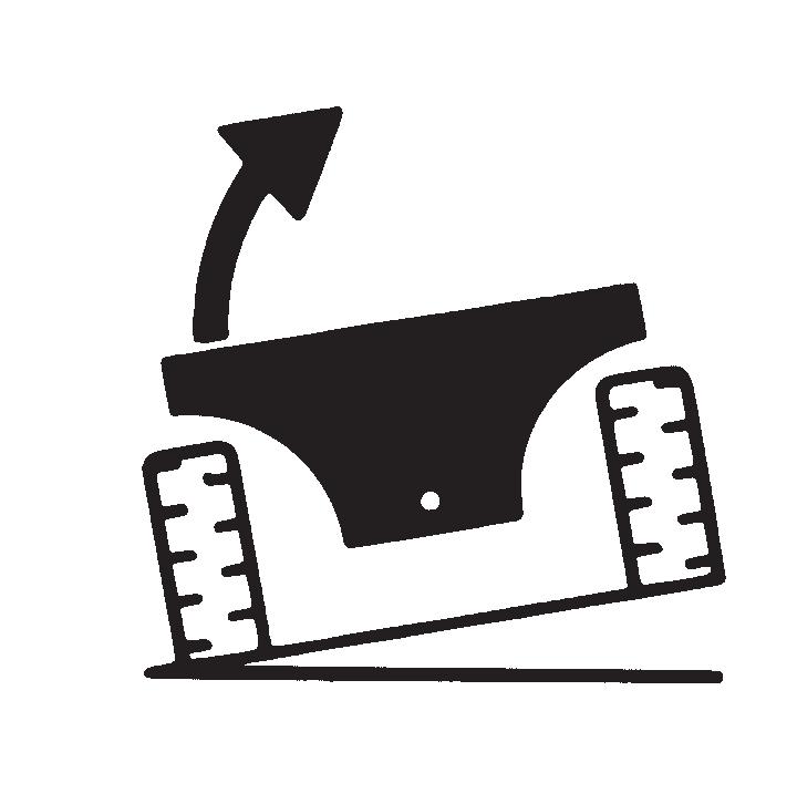


Outriggers Up (right side shown)
Outriggers Down (right side shown)

The information in this Operator’s Manual was written to give the owner/operator assistance in preparing, adjusting, maintaining and servicing of the Telescopic Handler. More important, this manual provides an operating plan for safe and proper use of the machine. Major points of safe operation are detailed in the SAFETY chapter of this manual.
Gehl Company asks that you read and understand the contents of this manual COMPLETELY, and become familiar with the machine before operating it.
This Telescopic Handler is primarily intended for use as a material handler. However, it may be equipped with an optional system: the Personnel Work Platform (PWP) System, which is intended for use when lifting personnel. When there is no other practical option available, this machine, when equipped with the PWP System, is approved for use to lift personnel, but only with an approved work platform, with the PWP System activated, and in full compliance with the “Mandatory Work Platform Safety Rules” (see SAFETY chapter).
Refer to the seperate operator’s/parts manual for information related to the optional Radio Remote Boom Control System.
The use of this Telescopic Handler is subject to certain hazards that cannot be eliminated by mechanical means, but only by the exercise of intelligence, care and common sense. It is therefore essential to have competent and careful operators, who are not physically or mentally impaired, and who are thoroughly trained in the safe operation of the equipment and the handling of the loads.
Throughout this manual information is provided that is set in italic type and introduced by the word IMPORTANT or NOTE. Be sure to read carefully and comply with the message or directive given. Following this information will improve operating and maintenance efficiency, help to avoid breakdowns and damage, and extend the machine’s life. A chart of standard hardware torques is located in the back of this manual.
A storage pocket in the back of the seat is provided for storing the Operator’s Manual. After using the manual, please return it to the pocket and keep it with the unit at all times! If this machine is resold, this manual should be given to the new owner.
If this machine was purchased “used,” or if the owner’s address has changed, please provide your Gehl dealer or Gehl Company Service Department with the owner’s name and current address, along with the machine model and serial number. This will allow the registered owner information to be updated, so that the owner can be notified directly in case of an important product issue, such as a safety update program.
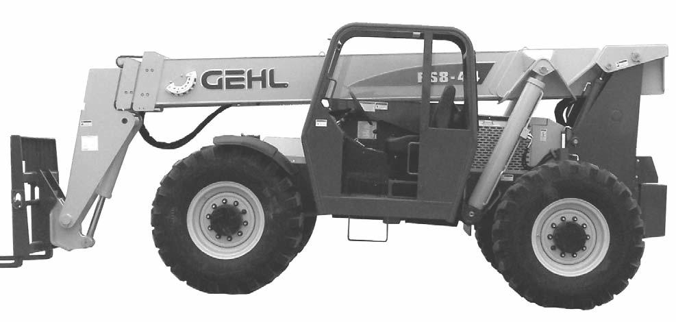
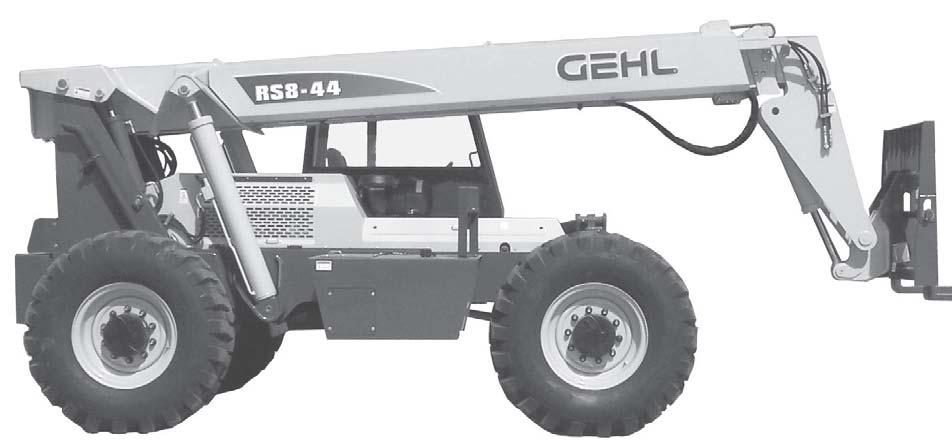
“Right” and “left” are determined from a position sitting on the seat and facing forward. The wide Gehl dealership network stands ready to provide any assistance that may be required, including genuine Gehl service parts. All parts should be obtained from or ordered through your Gehl dealer. Give complete information about the part and include the model and serial number of the machine. Record the serial number in the space provided on the previous page, as a handy record for quick reference.
Please be aware that Gehl Company reserves the right to make changes or improvements in the design or construction of any part without incurring the obligation to install such changes on any unit previously delivered.
Gehl Company, in cooperation with the Society of Automotive Engineers, has adopted this
Safety Alert Symbol
to identify potential safety hazards, which, if not properly avoided, could result in injury. When you see this symbol in this manual or on the machine itself, you are reminded to BE ALERT! Your personal safety is involved!

Quick-attach System
Identification
Boom Angle Indicator
Dash Indicators and Controls
Operator’s Station Lift Cylinder
Rear Boom Access
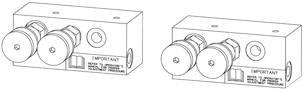
Stabilizer Cylinder
Slave Cylinder
Tilt Cylinder
Operator’s Seat
Extend Cylinder (inside boom)
Hydraulic Reservoir (under cover) Lift Cylinder
Access Covers
Frame Leveling Cylinder
Rear Lights and Backup Alarm Access
Telescopic Boom
Fuel Tank
Storage Compartment Battery Access
Side View Mirror
Auxiliary Hydraulics
Lifting Performance
Maximum lift capacity:
RS8-448000 lbs. (3628 kg)
RS8-428000 lbs. (3628 kg)
RS6-426600 lbs. (2994 kg)
Maximum lift height:
RS8-4444’ (13.4 m)
RS8-4242’ (12.8 m)
RS6-4242’ (12.8 m)
Capacity at maximum lift height:
RS8-44
Outriggers up:7000 lbs. (3175 kg)
Outriggers down:8000 lbs. (3628 kg)
RS8-42
Outriggers up:7000 lbs. (3175 kg)
Outriggers down:8000 lbs. (3628 kg)
RS6-42
Outriggers up:6600 lbs. (2994 kg)
Outriggers down:6600 lbs. (2994 kg)
Max. forward reach to load center:
RS8-4430’ 5” (9.3 m)
RS8-4228’ 3” (8.6 m)
RS6-4228’ 3” (8.6 m)
Capacity at maximum forward reach:
RS8-44
Outriggers up:1000 lbs. (454 kg)
Outriggers down:3000 lbs. (1360 kg)
RS8-42
Outriggers up:1000 lbs. (454 kg)
Outriggers down:3000 lbs. (1360 kg)
RS6-42
Outriggers up:1000 lbs. (454 kg)
Outriggers down:3000 lbs. (1360 kg)
Maximum below grade reach:
RS8-4416” (406.4 mm)
RS8-4214” (355.6 mm)
RS6-4214” (355.6 mm)
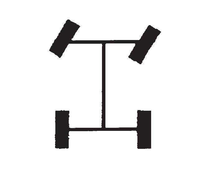
Frame Leveling: 10° left/10° right
General Dimensions
Based on standard machine equipped with listed tires, 48” masonry carriage and 48” pallet forks.
Recommended tire types:
13.00 x 24 - 12 PR
Inflate to 65 psi (450 kPa)
13.00 x 24 - 12 PR Rock
Inflate to 65 psi (450 kPa)
13.00 x 24 - 12 PR, foam filled
13.00 x 24 Solid rubber
14.00 x 24 - 12 PR
Inflate to 62 psi (430 kPa)
Overall length, less forks:
RS8-4419’ 10” (6.04 m)
RS8-4219’ 1” (5.81 m)
RS6-4219’ 1” (5.81 m)
Overall width: 8’ (2.4 m)
Overall height: 7’-8” (2.34 m)
Ground clearance: 16” (406 mm)
Wheel base: 9’11-1/2” (3.03 m)
Outside turn radius: 13’8” (4.2 m)