14 minute read
Transporting the Loader

from Gehl SL3640E SL3840E (EU) SL4240E SL4240E (EU) Skid-Steer Loaders Operator's Manual 917334-E0819
Park the truck or trailer on a level surface. Be sure the vehicle and its ramps have the weight capacity to support the loader. Make sure the vehicle surface and its ramps are clear of debris and slippery material that may reduce traction. Move the loader on and off the vehicle ramp slowly and carefully. Failure to follow these instructions could result in an overturn accident.
Observe all local regulations governing the loading and transporting of equipment. Ensure that the hauling vehicle meets all safety requirements before loading the skid-steer loader.
1. Place blocks at the front and rear of the hauling vehicle’s tires.

2. If the loader has an attachment, lift it slightly off the ground.
3. Back the loader slowly and carefully up the ramp onto the vehicle.
4. Lower the loader attachment to the vehicle deck, turn off the engine and remove the key.
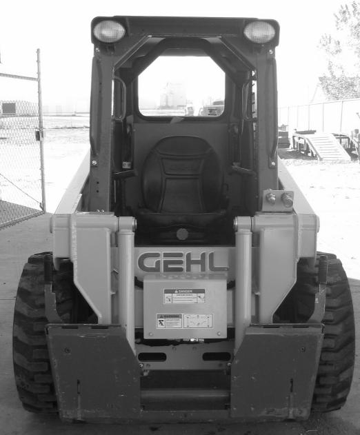
5. Fasten the loader to the hauling vehicle at the points indicated by the tiedown decals.
6. Measure the clearance height of the loader and hauling vehicle. Post the clearance height in the cab of the vehicle.
Warning
Before servicing the machine, unless expressly instructed to the contrary, exercise the MANDATORY SAFETY SHUTDOWN PROCEDURE (page 6).
After service has been performed, be sure to restore all guards, shields and covers to their original positions before resuming loader operation.
This Service chapter details procedures for performing routine maintenance checks, adjustments and replacements. Most procedures are referred to in the Troubleshooting and Maintenance Schedule Schedule chapters of this manual. Refer to the separate engine manual provided for engine-related adjustments, lubrication and servicing procedures.

Note: All service procedures, except those described under the “Dealer Services” topic are owner-operator responsibilities.
Important: More frequent service than the recommended intervals may be required under severe operating conditions. You must decide if your operation requires more service.
Important: Always dispose of waste lubricating oils and hydraulic fluids according to local regulations or take to a recycling center for disposal. Do not pour onto the ground or down the drain.
Dealer Services
The following areas of component service, replacement and adjustments require special tools and knowledge for proper servicing and should be performed only by your authorized Gehl skid-steer loader dealer: hydrostatic components, hydraulic system gear pump, valves, cylinders, electrical components (other than the battery, circuit breakers).
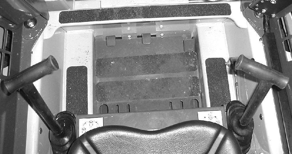
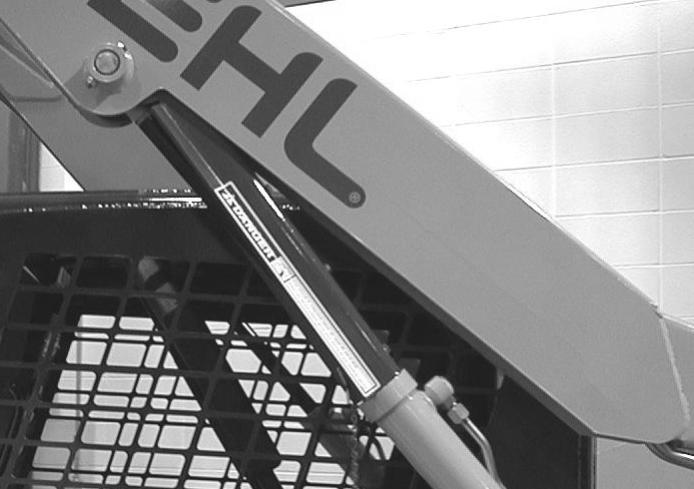
Tilting Back the ROPS/FOPS
For service, unbolt the two anchor bolts at the front of the ROPS/FOPS and tilt it back slowly, moving the control handles out of the way. A gas-charged spring helps tilt it back. A self-actuating lock mechanism engages to lock the ROPS/FOPS in a rolled-back position. To lower the ROPS/FOPS, apply upward force on it while pulling the lock mechanism handle toward the front of the loader. Lower the ROPS slowly onto the chassis, moving the control handles out of the way. Reinstall the anchor bolts, washers and locknuts.

Never operate the loader with the ROPS/FOPS removed or locked back. Be sure the lock is securely engaged when the ROPS/FOPS is tilted back. Properly support the ROPS/FOPS when unlatching the lock mechanism and lowering the ROPS/FOPS. Be sure to reinstall the anchor bolts, washers and locknuts before resuming loader operation.
Loader Raising Procedure
To raise the skid-steer loader so all four tires are off the ground, use the procedure below:
Do not rely on a jack or hoist to maintain the “raised” position without additional blocking and supports. Serious personal injury could result from improperly raising or blocking the skid-steer loader.
1. Using a jack or hoist capable of lifting the fully-equipped weight of the loader (with all attached options), lift the rear of the loader until the rear tires are off the ground.
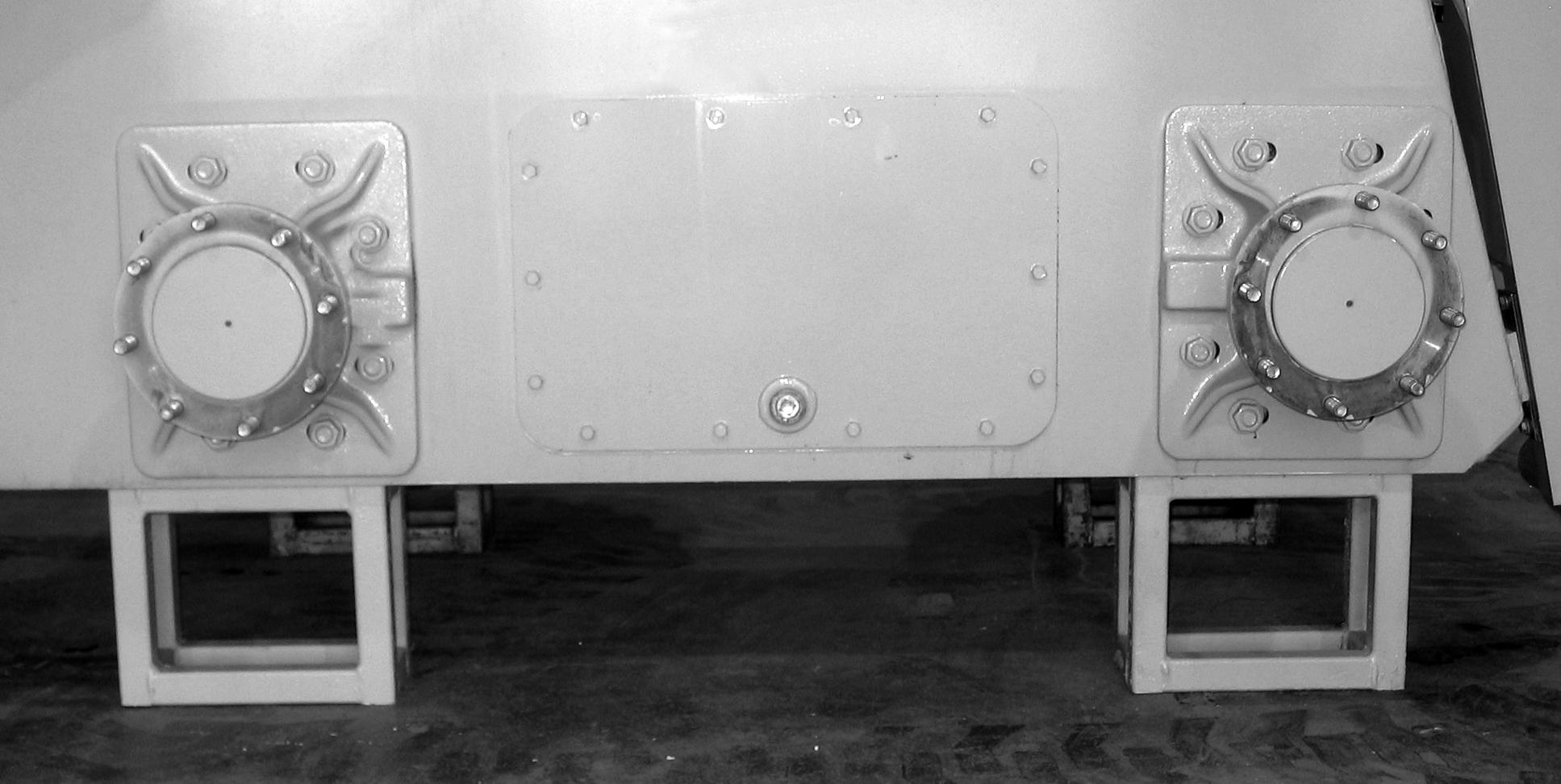
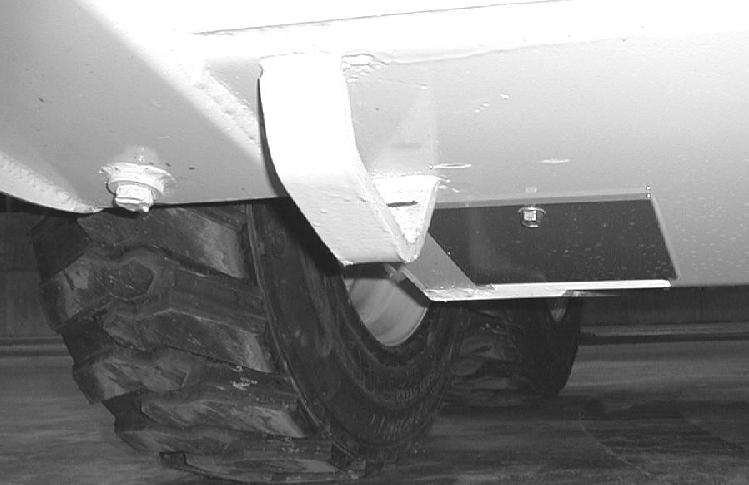
2. Stack wooden blocks under the flat part of the loader chassis. They should run parallel with, but not touch, the rear tires (Figure 25).
3. Slowly lower the loader until its weight rests on the blocks. If the tires still touch the ground, raise the loader again, add more blocks and lower again.
4. Repeat Steps 1 through 3 for the front end. When the procedure is finished, all four tires will be off the ground so they can be removed.
Loader Lowering Procedure
When service or adjustment procedures are complete, the skid-steer loader can be taken down from the “raised” position. To lower the loader onto its tires:
1. Using a jack or hoist, raise the front of the loader until its weight no longer rests on the front blocks.
2. Carefully remove the blocking under the front of the loader.
3. Slowly lower the loader until the front tires are resting on the ground.
4. Repeat Steps 1 through 3 for the rear of the loader. When the procedure is finished, all four tires will be on the ground and the blocks removed from under the loader.
Replacement Parts
Note: Part numbers may change. Your Gehl dealer will always have the latest part numbers.
Adjustments
Control Handles
The control handles do not require routine adjustment. Refer to the Service Manual for the initial setup procedure.
Fuel Sender
The fuel sender, located in the fuel tank, sends a signal to the fuel gauge indicating the amount of fuel left in the fuel tank.
Check the fuel sender periodically to ensure that the mounting screws are tight and that there is no fuel seepage around the gasket. If replacement is required, apply an RTV or gasket sealant around the gasket when restoring the fuel sender.
Engine Speed Control
The throttle cable does not require routine adjustment. Refer to the Service Manual for the initial setup procedure.
Besides throttle cable adjustment, the throttle lever friction pad pressure can be readjusted if the throttle lever does not hold its position. Belleville washers and a lock nut on the throttle lever are used for making this adjustment.
Drive Chains
The drive chains do not require routine adjustment. Refer to the Service Manual for the initial setup procedure.
Lubrication
Listed below are the locations, temperature ranges and types of recommended lubricants to be used when servicing this machine. Refer to the separate engine manual for more information regarding recommended engine lubricants, quantities required and grades.
Hydraulic System
Chaincases
Use Mobil DTE 15M or equivalent that contains anti-rust, anti-foam and anti-oxidation additives, and conforms to ISO VG46.
Capacity: 8 U.S. gallons (30,0 liters)
Use SAE15W-40 motor oil.
Capacity (each side): 8 U.S. quarts (7,6 liters)
Grease Fittings Use lithium based grease
Below 32°F (0°C) – Use SAE Grade* 10 or 10W-30
Above 32°F (0°C) – Use SAE Grade* 15W-40
Engine
*Service Classification: API - CH-4/CI-4
Capacity: 3-cylinder: 7.6 U.S. quarts (7,2 liters)
4-cylinder: 9.0 U.S. quarts (8,6 liters)
Refer to the following figure for grease fitting locations. Wipe dirt from the fittings before greasing them to prevent contamination. Replace any missing or damaged fittings. To minimize dirt build-up, avoid excessive greasing.
Engine Air Cleaner
Important: Failure to follow proper filter servicing instructions could result in catastrophic engine damage.
The air cleaner consists of an outer (primary) filter element and an inner (secondary) filter element. An air filter restriction indicator for monitoring the condition of the elements is located on the right side of the front of the air cleaner. If the air filter becomes restricted, this indicator will turn red to warn the operator that the element(s) require service. Push the reset button located on the end of the indicator after fitting a clean element. For replacement elements, refer to the “Replacement Parts” topic (page 45).

Note: Before replacing the filter element(s), push the reset button on the indicator. Start the engine and adjust the throttle to full speed. If the indicator does not turn red, do not replace the element(s).
The outer element should be replaced only when the restriction indicator turns red. The inner element should be replaced every third time the outer element is replaced, unless the outer element is damaged or the inner element is dirty.
Along with a daily check of the restriction indicator, check the air cleaner intake hose and clamps, and the mounting bracket hardware to be sure they are properly tightened.
Access
1. Open the rear door and engine access cover.
2. Unlatch the clamps on the air cleaner and remove the cover. Clean out any dirt built up in the cover assembly.
Outer Element
1. Carefully pull the outer element out of the housing. Never remove the inner element unless it is to be replaced.
2. Clean out any dirt built up in the housing. Leave the inner element installed during this step to prevent debris from entering the engine intake manifold.
3. Replace the outer element.
Note: Gehl does not recommend cleaning the outer element.
4. Use a trouble light inside the outer element to inspect for spots, pinholes or ruptures. Replace the outer element if any damage is noted. The outer element must be replaced if it is oil- or soot-laden.
Inner Element
Note: Replace the inner element only if it is dirty or if the outer element has been replaced three times.
1. Before removing the inner element from the housing, clean out any dirt built up in the housing. Leave the inner element installed during this step to prevent debris from entering the engine intake manifold.
2. Remove the inner element.
Reinstallation
1. Check the inside of the housing for any damage that may interfere with the elements.
2. Be sure that the element sealing surfaces are clean.
3. Insert the element(s), making sure that they are seated properly.
4. Secure the cover to the housing with clamps.
5. Check the hose connections and be sure they are all clamped and tightened properly.
6. Reset the restriction indicator by pressing the reset button.
Engine Service
Check Engine Mounting Hardware
All bolts that secure the engine mounting brackets to the engine and the loader frame should be checked and re-tightened as necessary.
Allow hot engine and hydraulic system components to cool before servicing.
Checking Engine Oil Level
Important: For new units, the initial oil change should be after the first 50 hours.
Open the rear door and engine access cover. Pull out the dipstick and check the oil level. Markings on the dipstick represent FULL and LOW (add oil) levels.
Refer to the Maintenance Interval Chart (page 69) for the service interval for replacing the engine oil and filter.
Changing Engine Oil and Filter
1. Run the engine until it is at operating temperature. Stop the engine. Remove the rear belly pan.

2. Remove the drain plug.
3. From the engine compartment, remove the oil filter. Clean the filter sealing surface.
4. Put clean oil on the new oil filter gasket. Install the filter and tighten 3/4 of a turn past the point where the gasket contacts the filter head.
5. Reinstall and tighten the drain plug.
6. Remove the oil cap and add the recommended oil. Refer to the “Lubrication” topic in this chapter for oil specifications and capacities.
7. Start the engine and let it run for several minutes at low idle. Stop the engine. Check for leaks at the oil filter, drain plug and remote oil drain hose. Check the oil level. Add oil if it is not at the top mark on the dipstick.
For a replacement element, refer to the “Replacement Parts” topic (page 45).
Changing Fuel Filter
The engine has a fuel filter located on the left side of the engine. To change it:
1. Shut off the fuel supply by turning the fuel shutoff valve on top of the water trap.
2. Shut off return line by turning valve on the fuel tank.
3. Remove the fuel filter element.
4. Lubricate new fuel filter element gasket with diesel fuel.
5. Install and tighten the filter element one-half turn past point the where the gasket contacts the filter head.
6. Turn shutoff valve on water separator to ON.
7. Turn on the fuel supply at fuel tank.
The engine is self-priming. To remove air before starting, turn the ignition key to the ON position for 30 seconds.
For a replacement element, refer to the “Replacement Parts” topic (page 45).
Servicing Water Separator
Periodically check for water in water separator by checking level of float in water separator bowl. If water is present:
1. Shut off the fuel supply by turning the fuel shutoff valve on top of the water separator.
2. Turn nut to release the bowl from the valve head. Dispose remaining fuel and water.
3. Clean bowl and filter element with warm water until all foreign material is removed. Replace fuel filter if damaged. Refer to Parts Manual for part number.
4. Place element onto valve head. Lubricate o-ring on bowl with diesel fuel and place on valve head. Turn nut to tighten.
5. Turn on fuel supply.
Releasing Water from Separator
1. Check red float located in the water separator bowl. If red float is raised, open valve on the bottom of the bowl to drain water.
2. Close valve quickly after float reaches the bottom of the bowl.
Spark Arrestor Muffler
Important: The loader is factory-equipped with a spark arrestor type muffler. Muffler maintenance is required to keep it in working condition. Refer to local laws and regulations for spark arrestor requirements.
1. Stop the engine, open the rear door and engine cover.
2. Remove the plug from the bottom of the muffler.
3. Block the outlet of the muffler with a non-combustible material.
4. Start the engine and run it for 10-15 seconds.
5. Stop the engine and remove the blockage.
6. Put anti-seize coating on the plug.
7. Reinstall and tighten the plug.
Alternator/Fan Belt
Refer to the separate engine manual for setting proper belt tension. If the belt is worn, cracked or otherwise deteriorated, replace the belt by following the procedure in the separate engine manual.
Hydraulic System
Checking Hydraulic Oil Level
The loader has a dipstick located in the engine compartment. Check the fluid level with the lift arm lowered and the attachment on the ground. When hydraulic fluid is required, allow the system to cool. Slowly remove the oil fill cap, allowing the pressure to dispel before removing the cap completely. Add hydraulic fluid as required. Refer to the Lubrication topic (page 46) for oil recommendations. Replace the cap.
Changing Hydraulic Oil Filter
Warning
Before servicing the hydraulic filter, be sure the lift arm is lowered.
1. Open the rear door and engine cover to access the filter. Unscrew the filter.

2. Clean the surface of the filter housing where the element seal contacts the housing. Put clean oil on the rubber gasket of the new filter element.
3. Install and tighten the filter element 3/4 of a turn past the point where the gasket contacts the filter head.
4. For a replacement element, refer to the Replacement Parts topic (page 45).
Changing Hydraulic Oil
The hydraulic oil must be replaced if it becomes contaminated, after major repairs, and after 1000 hours or one year of use.
1. Remove the oil filler cap.
2. Install a catch pan of sufficient capacity under the oil reservoir (8 gallons [30 liters])
3. Remove the drain plug located on the bottom left of the oil reservoir.
4. Remove and replace the hydraulic oil filter.
5. Reinstall the drain plug.
6. Refill the reservoir until the oil is between the two lines on the dipstick gauge.
7. Start the engine and operate the hydraulic controls.
8. Stop the engine and check for leaks at the filter and reservoir drain plug.
9. Check the fluid level and add fluid if needed.
Cooling Systems
Important: Check the cooling system every day to prevent overheating, loss of performance or engine damage.
Checking Coolant Level
1. Open the rear door. Check the coolant level in the coolant recovery tank on the inside of the rear door. The coolant recovery tank must be 1/3 to 1/2 full with a cold engine and 2/3 to 3/4 full with a hot engine.
2. Allow the coolant to cool. Do not remove the cap when the coolant is hot. Serious burns may occur.
3. Add premixed coolant, 50% water and 50% ethylene glycol, to the recovery tank if the coolant level is low.
Cleaning Cooling System
1. Park the loader on a level surface, lower the lift arm and stop the engine. Allow the engine to cool.
2. Open the rear door. Lift the engine cover.
3. Clean the radiator and oil cooler by blowing through the fins with high pressure water or air.

Note: The radiator can be tipped out for cleaning by loosening and rotating the over-center links on each side. This will also help in cleaning the oil cooler.
Draining/Flushing Cooling System
1. Open the rear door. Lift the engine cover.
2. Slowly remove the radiator cap, allowing pressure to dispel before removing completely.
Warning
Liquid cooling systems build up pressure as the engine becomes hot. Before removing the radiator cap, stop the engine and let the system cool. Remove the radiator cap only after the coolant has cooled. Remove the cap slowly or severe burns may result.
3. Remove the drain plug and drain the coolant into a suitable container.
4. Replace the drain plug.
Note: Protect the cooling system by adding premixed 50% water and 50% ethylene glycol to the system. This mixture will protect the cooling system to -34°F (-36°C).
5. Fill the radiator fully and the recovery tank half full with the premixed coolant.
6. Reinstall the radiator cap.
7. Run the engine until it is at operating temperature. Stop the engine and let it cool. Check the coolant level. Add more coolant if required.
Chaincases
The chaincase contains the drive sprockets and drive chains. There are two plugs in each chaincase. One is to drain the fluid and the other is to check the fluid level. Refer to the Maintenance Schedule chapter (page 69) for change intervals. Refer to the Lubrication topic (page for information on oil type and quantity.
Checking and Adding Oil
1. Park the loader on a level surface. Stop the engine.
2. Remove the check plug from each chaincase housing. If the oil can be reached with the tip of your finger, the oil level is adequate.
3. If the level is low, add fluid through the check plug until the oil level reaches the edge of the hole. Reinstall the check plug.
Draining Oil
1. Raise the rear of the machine to aid in draining the chaincases.
2. Remove the drain plug on each chaincase and drain the oil into a suitable container.
3. Reinstall and tighten the drain plugs.
4. Refill the chaincases at the check plugs.
Seat and Restraint Bar Switches
Electrical switches in the seat and restraint bar must be closed (operator sitting in the seat and restraint bar lowered) to complete the circuit and start the engine.
Bucket Cutting Edge
The bucket cutting edge should be replaced when it is worn to within 1 in. (25 mm) of the bucket body.
Wheel Nuts
Wheel nut torque must be checked before initial operation and every two hours thereafter until the wheel mounting hardware torque stabilizes at the recommended setting of 120-130 ft-lbs (161-175 N·m). When tires are removed and replaced, this procedure must be repeated.
Tires
Rear tires usually wear faster than the front ones. To keep tire wear even, rotate the tires from front to rear and rear to front.
It is important to keep the same size tire on each side of the loader to prevent excessive wear on tires or other damage. If different sizes are used, each tire will be turning at different speeds, causing excessive wear.
The tread bar of all tires must face the same direction.
Mounting Tires
Inflating or servicing tires can be dangerous. When possible, trained personnel should service and mount tires. To avoid possible death or serious injury, follow the safety precautions below.
Warning
1. Be sure the rim is clean and free of rust.
2. Lubricate the tire beads and rim flanges with a soap solution. Do not use oil or grease.
3. Use a clip-on tire chuck with remote hose and gauge, allowing you to stand clear while inflating the tire. Do not place your fingers on the tire bead or rim during inflation.
4. Never inflate beyond 35 psi (240 kPa) to seat the beads. If the beads have not seated by the time the pressure reaches 35 psi (240 kPa), deflate the assembly, reposition the tire on the rim, lubricate both parts and re-inflate. Inflation pressure beyond 35 psi (240 kPa) with unseated beads may break the bead or rim with explosive force sufficient to cause death or serious injury.
5. After seating the beads, adjust the inflation pressure to the recommended operating pressure.
6. Do not weld, braze or otherwise attempt to repair and use a damaged rim.