10 minute read
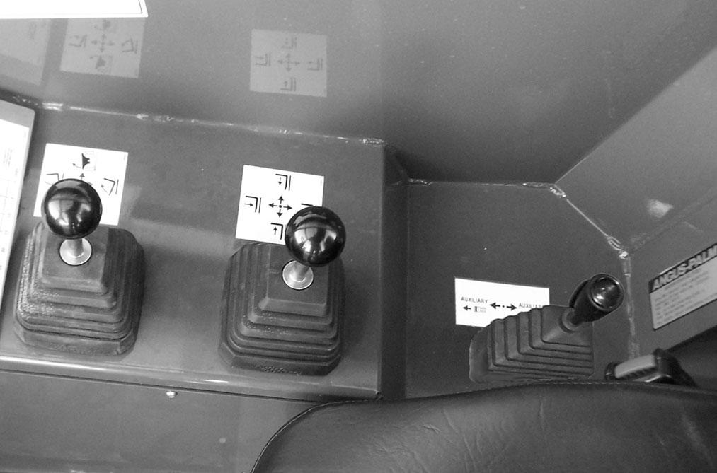
Two-Joystick Configuration


Frame Level and Attachment Joystick
Boom Control Joystick
Auxiliary Hydraulics Control: This two-position lever is for attachment tools that require additional hydraulics.
Tri-Function Joystick Configuration
Boom, Attachment and Auxilliary Hydraulic Joystick
Frame Level Control
Auxilliary Hydraulics Control
Two-Joystick Configuration
Frame Level/Attachment Tilt Joystick: The machine may be tilted slowly as much as 10°to the left or right to level the frame and boom in relation to the ground. Move the joystick handle to the left to tilt to the left; move the joystick handle to the right to tilt to the right.
Warning
DO NOT level the frame with the boom raised or extended. Level the frame ONLYwhile stopped, with the boom fully retracted and the attachment raised just enough to clear the ground.
To tilt the attachment tool up, move the joystick handle rearward. To tilt the attachment tool down, move the joystick handle forward.
After the operator tilts the attachment tool to a desired angle, that angle will be maintained as the boom is raised and lowered, extended and retracted, until a new angle is set.
Boom Control Joystick: This machine has a hydraulic-type boom with telescopic sections. The sections extend by means of a hydraulic cylinder and chain system inside the boom, sequenced for uniform extension of each section.
To extend the boom, move the joystick handle to the right; to retract the boom, move the joystick handle to the left. To raise the boom, move the joystick handle rearward; to lower the boom, move the joystick handle forward.
Tri-Function Joystick: This joystick handle is equipped with two yellow buttons and two blue buttons on the upper rear of the handle, and a trigger switch on the front of the handle. The yellow buttons operate the attachment tilt. The blue buttons operate the auxiliary hydraulics. The trigger switch increases the function speed of both the attachment tilt and auxiliary hydraulics.
To extend the boom, move the joystick to the right; to retract the boom, move the joystick to the left. To raise the boom, move the joystick rearward; to lower the boom, move the joystick forward.
To tilt the attachment tool up, depress and hold the lower yellow button on the left side of the joystick handle; to tilt the attachment tool down, depress and hold the upper yellow button on the left side of the joystick handle.
To operate the auxiliary attachment hydraulics, depress and hold either the upper or lower blue button on the right side of the joystick handle. The upper blue button will cause the reverse effect of the lower blue button.
Depressing and holding the trigger on the front side of the joystick handle will increase the speed of the attachment tilt and auxiliary hydraulic functions.
NOTE: The joystick handle does not need to be moved to operate the tilt or auxiliary hydraulic functions.
Speed Control Knobs: The tri-function joystick incorporates a manually adjusted speed control. Speed adjustment is accomplished through the manual adjustment of pilot-pressure apply valves located next to the main valve at the rear of the machine.
NOTE: There is a locking knob located forward of the adjusting knob, which must be loosened before the adjusting knob can be turned. After adjustment has been made, tighten the locking knob to maintain the selected speed.
Frame Level Control: This control is located to the rear of the tri-function joystick. The machine may be tilted slowly as much as 10° to the left or right to level the frame and boom in relation to the ground.
Warning
DO NOT level the frame with the boom raised or extended. Level the frame ONLYwhile stopped, with the boom fully retracted and the attachment raised just enough to clear the ground.
Operation Indicators
Frame Angle Indicator: Located in front of the operator on the ROPS upper cross tube, the position of the ball indicates when the frame is level relative to a sloping ground surface.
Indicator
Boom Angle Indicator: Mounted on the left side of the outer boom, the movement of a ball indicates the angle of boom elevation relative to the ground.
If the machine is equipped with auxiliary hydraulics, there will be two pilot-pressure apply valves, each having two speed-control knobs. The top pilot valve controls the auxiliary hydraulics, and the lower pilot valve controls the attachment tilt function. On the attachment tilt pilot valve, the left knob controls the attachment tilt-back speed, and the right knob controls the attachment tilt-forward speed. On the auxiliary hydraulic pilot valve, the function of the knobs will depend on the type of attachment requiring auxiliary hydraulics.
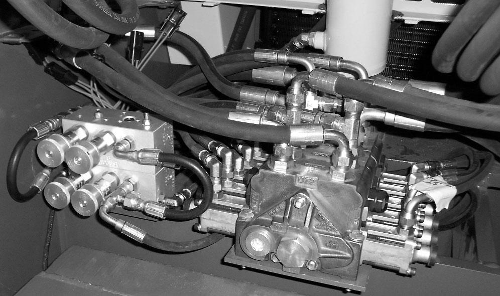
Turning a knob clockwise will increase the speed of its associated function. Turning a knob counter-clockwise will decrease the speed of its associated function.
Boom Angle Indicator
Service And Safetyfeatures
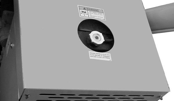
Coolant Level: The radiator cap is located under the opening toward the rear of the main hood section.
Engine Oil Level: The dipstick is located on the right side of the engine.
Transmission Oil Level: The dipstick is located under the access cover on the front hood section.
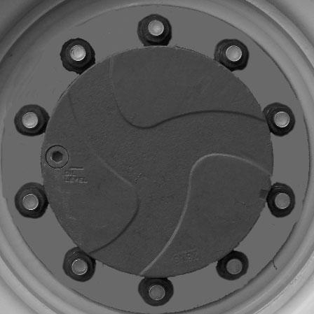
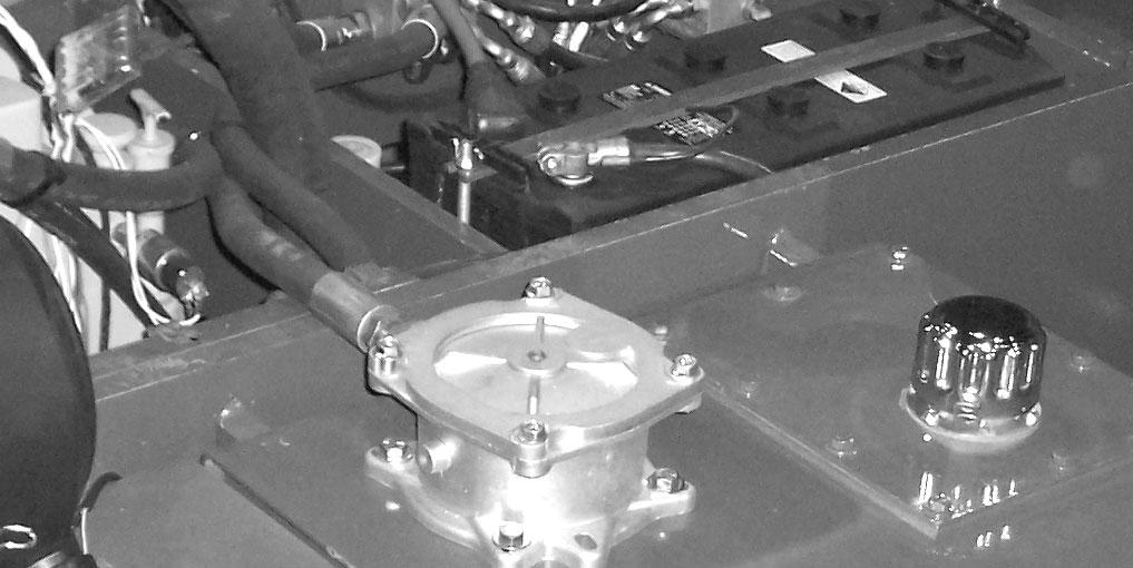
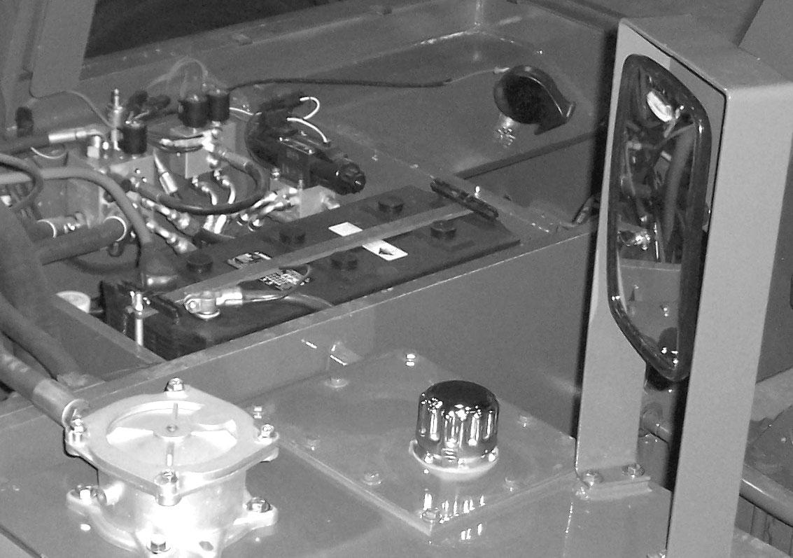
Hydraulic ReservoirOil Level and Fill Cap: The dipstick on the fill cap of the reservoir indicates the level of the hydraulic oil in the reservoir.
Engine Oil Dipstick
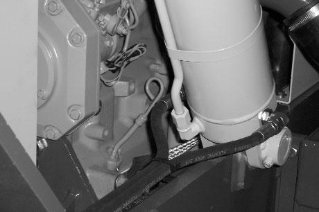
Hydraulic Pressure Test Ports: Agauge can be attached to these ports to check main valve, joystick and steering pressures.
Side-View Mirror: Located on the front outside corner of the fuel tank, this mirror provides the operator with a view toward the rear of the machine.
Battery Compartment: The battery is located under the access cover on the front hood section.

Hydraulic Test Ports
Side-View Mirror Battery Compartment
Transmission Dipstick
Hydraulic Fill Cap/Dipstick
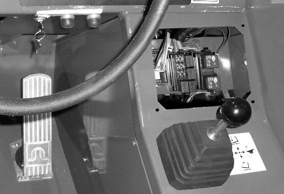
Fuse and Relay Compartment: This compartment is located under the load chart panel. Remove the four screws to gain access to the fuses and relays.
Fuse and Relay Access
Attachment Tools
Gehl Company offers a range of attachment tools to meet various lifting and material-handling applications. Contact your Gehl dealer for specifications and ordering information.
Accessories
Backup Alarm: Located inside the rear frame cover, this alarm produces a loud warning sound when the machine is in reverse.
Backup Alarm
Gehl also offers a range of special accessories for this machine. Contact your Gehl dealer for specifications and ordering information.
NOTE: All accessories are field-installed unless otherwise noted. Information and parts for installing accessories are provided by your Gehl Telescopic Handler dealer or Gehl Company.
Chapter 6 OPERATION AND ADJUSTMENTS
Generalinformation
Caution
BEFORE starting the engine and operating the Telescopic Handler, review and comply with ALLsafety recommendations in the SAFETY chapter of this manual. Know how to STOPthe machine before starting it. Also, BE SURE to fasten and properly adjust the seatbelt.
ENGINE BREAK-IN
Anew engine does not require extensive “break-in.” However, for the first 100 hours of operation: Allow the engine to idle for a few minutes after every cold start, DO NOTidle the engine for long periods of time, DO NOToperate the engine at maximum power for long periods of time, and check the oil level frequently, and replenish as necessary with the oil specified in the engine manual.
John Deere engines use a “break-in” oil for the first 100 hours of operation. After the first 100 hours of operation, change the oil and replace the oil filter. Consult the Lubrication chapter or the engine manual for the type of oil to use in the engine. Refer to the Service and Storage chapter for the proper service intervals.
PRE-START INSPECTION
It is the operator’s responsibility to inspect the machine before the start of each workday. Every pre-start inspection must include more than checking the fuel and oil levels. It is a good practice to personally inspect any machine you are assigned to use, even if it has already been checked and put into service by other personnel.
The most efficient method of checking a machine is by conducting a “Walk-Around Inspection.”
Before mounting the operator’s compartment, walk completely around the machine to be sure no one is under, on, or close to it. Let others in the area know you are going to start up and wait until everyone is clear of the machine.
Before Starting Engine
Before starting the engine and running the machine, refer to the Indicators and Controls chapter and become familiar with the various operating controls, indicators and safety features.
Starting The Engine
Warning
ALWAYS fasten your seat belt BEFORE starting the engine. Leave the parking brake applied until the engine is running and you are ready to operate the machine.
The following procedure is recommended for starting the engine:
1.Grasp the handholds and step up into the operator’s compartment.
2.Adjust the seat and fasten the seatbelt.
3.Check that all controls are in their “neutral” positions, except the parking brake switch, which should be in the “ON” position.
4.Turn the key switch to “ON” position and press the start button. If the button is released before the engine starts, turn the key switch to “OFF” position and allow the starter to stop before attempting to start again.
IMPORTANT: Crank the starter until the engine starts. If the engine fails to start within 30 seconds, return the key to the “OFF” position, wait two minutes, and try to start the engine. Cranking the engine for longer than 30 seconds will result in premature failure of the starter.
5.After the engine starts, allow a sufficient warm-up time before attempting to operate the controls.
6.Check that indicators are in their normal operating conditions.
7.Verify that there are no fuel, oil or engine coolant leaks, and no abnormal noises or vibrations.
Cold Starting Procedures
Ablock heater or radiator lower hose heater is recommended for starting in temperatures of 20°F (-7°C) or lower. See your Gehl dealer for recommended heater.
If prevailing temperature is 40°F (4°C) or below, it may be necessary to use a cold weather starting aid to start the diesel engine. For proper use of starting aids, check the instructions in the engine manual.
If the battery becomes discharged and has insufficient power to start the engine, jumper cables can be used for starting assistance. Refer to the jump starting instructions in the Service and Storage chapter of this manual for safe jump starting procedures.
Stopping
The following procedure is the recommended sequence for stopping the machine:
1.Bring the machine to a stop on a level surface. Avoid parking on a slope, but if necessary park across the slope and block the wheels.
2.Fully retract the boom and lower the attachment to the ground. Idle the engine for gradual cooling.
3.Place controls in neutral. Apply the parking brake.
4.Turn the ignition switch key to the “OFF” position. Remove the key.
5.Unfasten the seatbelt, and grasp the handholds while climbing out of the operator’s compartment.
First Time Operation
Make sure the engine is warm and then go through the following procedures:
Caution
Be sure the area being used for test-running is clear of spectators and obstructions. Initially, operate the machine with an empty attachment tool.
Place the travel lever in Forward or Reverse and select a speed range. Switch off the parking brake and move ahead slowly, while testing the steering and brakes. Stop and operate all boom, attachment tool functions and frame leveling controls, checking for smooth response.
Apply the service brakes, and move the travel lever to the opposite direction (forward or reverse).
Shifting to the next higher gear may be done at any engine speed while the machine is in motion.
DO NOToverspeed the engine when down-shifting. Allow the machine to slow down before shifting to the next lower gear.
Parking Brake
NOTE: The parking brake mechanism within the front axle is not designed for, and not intended to be used as, the primary means of stopping movement of the machine. Hydraulic braking provided through the service brakes within the axles is the primary means for stopping movement. The axleby-axle split brake system is the secondary means of stopping movement.
The proper sequence for correct machine operation is to always engage the parking brake switch before shutting off the engine; and to disengage the parking brake ONLYafter the engine is running. In an emegency however, if it becomes necessary to stop movement, activate the parking brake switch to “ON.”
Changing Attachment Tools
The Telescopic Handler boom nose will accept Gehl Quick-attach System attachment tools. The Quickattach System has a quick-release hookup and locking mechanism for mounting framing-type or masonrytype attachment tools to the boom nose.
Attaching
To pick up an attachment tool, proceed as follows:
1.Raise the boom slightly and extend it two to three feet (600 to 900 mm) for better visibility. Tilt the tool carrier forward.
2.Align the tool carrier squarely with the back of the attachment tool.
3.Slowly extend the tool carrier and lower the hooks under the attachment tool hookup bar.
4.Tilt the tool carrier back so that the lock plate engages the attachment tool. This secures the attachment tool to the Quick-attach System.
5.For an attachment tool with auxiliary hydraulics, connect hoses to the quick-disconnect connectors on the boom nose.
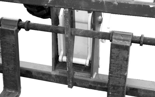
Quick-attach System Attaching Detail

Detaching
To detach the attachment tool, proceed as follows:
1.Raise the boom slightly and extend it two to three feet (600 to 900 mm) for better visibility. Lower the boom until the attachment tool is approximately 12” (0.3 m) off the ground.
2.Roll back the carrier as far as it will go. When the carrier is rolled back completely, perform the Mandatory Safety Shutdown Procedure (Safety chapter, page 8).
3.With the engine off, leave the operator’s station and manually raise the lock spring and flip the lock plate up and outward at least 180° so that it is in position to re-lock onto the next attachment tool.
4.Tilt the Quick-attach System forward to allow the attachment tool to roll out, then lower the boom so that the hook ears clear the hookup bar on the attachment tool.
NOTE: One side of the lock plate has a bright red decal to indicate the unlocked position.
5.If the attachment tool has auxiliary hydraulics, disconnect the hoses from the quick-disconnects on the boom nose.
6.Start the engine and roll the Quick-attach System forward. Slowly back the machine until the attachment tool is free from the boom nose.
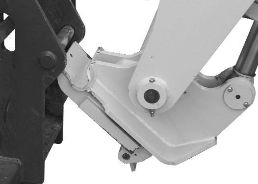
Quick-attach System Detaching Detail
Warning
Modifications, alterations to, or use of attachment tools not authorized by Gehl (or the manufacturer) in writing can void warranty and cause machine damage and/or serious personal injury or death.
SELF-LEVELING
The machine is equipped with a hydraulic self-leveling feature. This feature is designed to keep the attachment tool level while the boom is being raised.