8 minute read
SAFETY


Chapter 5
Indicators And Controls
Guards And Shields
Caution
Become familiar with and know how to use ALLsafety devices and controls on the Telescopic Handler BEFORE operating it. Know how to stop the machine operation BEFORE operating it. This Gehl machine is designed and intended to be used ONLYwith a Gehl Company attachment tool, or a Gehl Company approved accessory or referral attachment tool. Gehl Company cannot be responsible for product safety if the machine is used with a non-approved accessory or attachment tool.
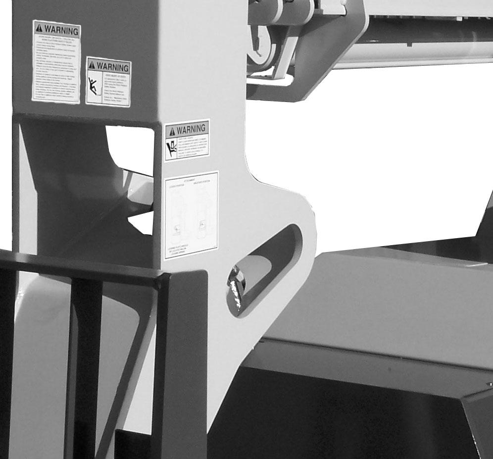
Whenever possible and without affecting machine operation, guards and shields are used to protect potentially hazardous areas. In many places, decals are also provided to warn of potential hazards and to display special operating procedures.
Warning
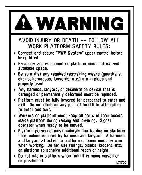
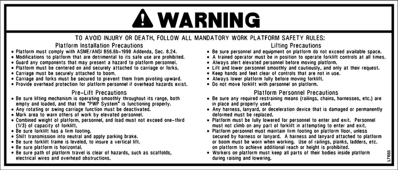
Read and thoroughly understand all safety decals on the Telescopic Handler BEFORE operating it. DO NOT operate the machine unless all factory-installed guards and shields are properly secured in place.
Boom Angle Indicator
Frame Angle Indicator
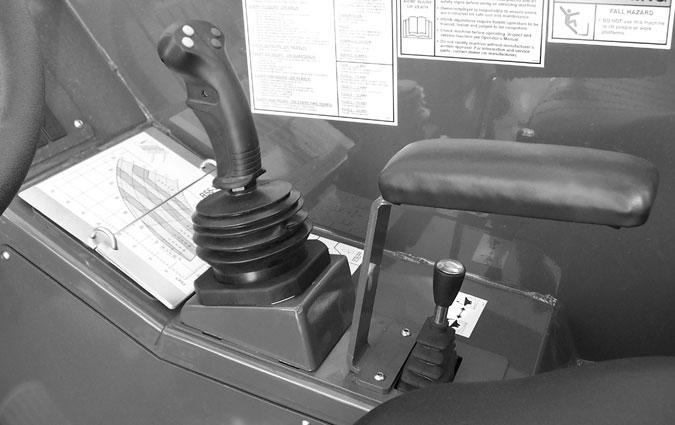
Boom Control Joystick
Auxiliary Hydraulics Control
Frame Level and Attachment Joystick
Speed and Travel Direction Lever
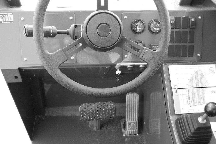
Steering Wheel
Brake Pedal
Instrument and Switch Panel
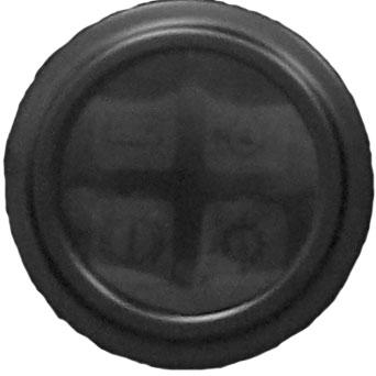
Horn Button
Load Zone Charts
Frame Level Control
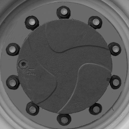
Brake Fluid Reservoir
Key Switch Start Button
Throttle Pedal
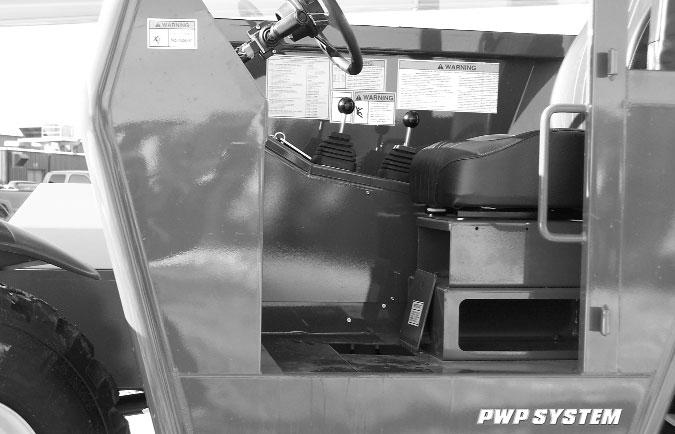
Operator’s Compartment and Indicators/Controls Locations
Dash Panelarea
Key Switch OFF: When the key is vertical in the keyswitch, power is disconnected from the battery to the control and instrument panel electrical circuits. This is the only position in which the key can be inserted or removed.
Key Switch ON: When the key is turned one position clockwise from the vertical (OFF) position, power from the battery is supplied to the engine and all control and instrument panel electrical circuits.

NOTE: If the engine requires repeated attempts to start, the key MUST be returned to the OFF position between starting attempts to prevent battery run down.
Start Button: With key switch in the ON position, press the start button to activate the starter. Release it as soon as the engine starts.
Horn Button: With the key switch ON, press the horn button to activate warning sound.
Load Zone Charts: Aseries of flip charts show lift height and reach limits relative to the load weight being handled with various attachment tools.
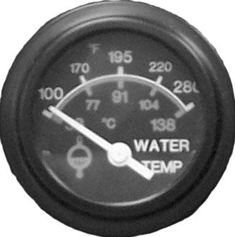
Coolant Temperature Gauge: The upper right gauge in the instrument panel, it indicates the temperature of the engine coolant. Under normal conditions, this gauge should indicate approximately 185°F (85°C).
Lamp ClusterGauge: The lower left gauge in the instrument panel, it contains four indicator lamps. The functions of these lamps are as follows:
AlternatorLamp: Located in the upper left section of the lamp cluster gauge, this lamp indicates the condition of the electrical charging system. During normal operation, this lamp should be off. If the charge rate is too high or too low, this lamp will come on.
Engine Oil Pressure Lamp: Located in the upper right section of the lamp cluster gauge, this lamp indicates whether the engine lubricating oil pressure is sufficient. During normal operation, with the engine running, this lamp should be off. During starting and when the engine is not running, this lamp will be on.
IMPORTANT: If this lamp comes on during normal operation with the engine running, stop the engine immediately! After allowing the oil to drain down for a few minutes, check the engine oil level. Maintain oil level at the FULLmark on the dipstick.
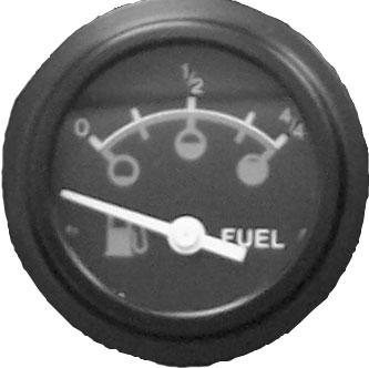
Fuel Level Gauge: The upper left gauge in the instrument panel, it indicates the amount of fuel in the fuel tank.
Brake Failure Lamp: Located in the lower left section of the lamp cluster gauge, this lamp indicates the condition of the service brake system. The front and rear brakes are on independent systems. If a loss of pressure occurs in either system during normal operation with the brake pedal depressed, this lamp will come on.
Failure in one of the brake systems does not affect the operation of the other system. However, the MANDATORYSAFETYSHUTDOWN PROCEDURE (p. 8) should be followed and any necessary repairs made immediately.
During normal operation this lamp should remain off.
Transmission Oil Temperature Lamp: Located in the lower right section of the lamp cluster gauge, this lamp indicates whether or not the transmission oil is at the proper temperature. During normal operation this lamp should be off, indicating that the transmission oil system is at the proper temperature.
IMPORTANT: If this lamp comes on during normal operation, a problem may exist in the transmission oil system. Stop the machine immediately and investigate the cause of the problem!
Hourmeter: Located to the right of the lamp cluster gauge, it indicates the total operating time of the machine and should be used for keeping the maintenance log.
Top Row Switches
Switches have graphic symbols to indicate function and effect. The following descriptions start with the first switch on the left.
Steering Mode: This 3-position switch is used to select among the three steering modes. The upper position engages the 4wheel-steer mode. This mode provides allwheel steering, used for making tighter turns, usually on a jobsite. The center position engages the 2-wheel-steer mode. This mode provides front-wheel steering only, used for higher speed travel. The lower position engages the crab-steer mode. This mode is used when a small amount of side shift is needed for picking or placing a load.
NOTE: The rear wheels are not self-centering. Make sure all wheels are in a straight-ahead position before changing the steering mode.
Any of the steering modes can be used in forward and reverse travel. The operator should learn to anticipate changes in machine movement if the steering mode must be changed.
Clutch Cutout: When activated, this switch allows faster engine acceleration and more power to the hydraulic system, without power to the drive axles, while the service brake pedal is pressed.
In the “OFF” position, the clutch mechanism of the transmission remains engaged when the brakes are applied. In the “ON” position, the clutch mechanism is disengaged when the brakes are applied.
Normal brake force will hold the machine in position while accelerating the engine to power hydraulic control functions during load placement.
Parking Brake: When the machine is parked, this switch should be pressed to actuate the parking brake mechanism in the front axle.
Warning
Unattended Machine Hazard
Activate parking brake switch and lower attachment tool to ground before leaving machine. An unattended machine can move or roll and cause death or serious injury to operator or bystanders.
Periodically check the parking brake operation to maintain adequate holding power. Always be sure the parking brake switch is off when resuming machine operation.
Middle Row Switches
Switches have graphic symbols to indicate function and effect. The following descriptions start with the first switch on the left.
NOTE: Some switches are optional and may not be on machine.
Head Lights/Work Lights: Pressing the top of the switch will illuminate the lights mounted on the top of the operator’s station and the red tail lights, for use in forward travel operations. Pressing the bottom of the switch will illuminate the lights at the end of the boom in addition to the lights on the operator’s station, for additional lighting in working operations.
Turn Signal: This switch is used to indicate the direction of a turn with the tail lights. Press the right arrow for a right turn; press the left arrow for a left turn. Return the switch to the center position after the turn is completed.
Hazard: This switch can be activated to make the tail lights flash on and off in case the machine is stalled or temporarily stopped in a traffic area on the road or jobsite.
Personnel Work Platform: This is a red switch used to activate the Personnel Work Platform System. When activated, an amber lamp in the switch will be on.
NOTE: This lamp will flash on and off, indicating that the system is not yet fully functional, until the brakes are held on for three or more seconds.
Bottom Row Switches
Switches have graphic symbols to indicate function and effect. The following descriptions start with the first switch on the left.
NOTE: Some switches are optional and may not be on machine.
Wiper/Washer: The windshield and top window of the operator’s station are each equipped with a wiper and washer mechanism. The left switch operates the wiper and washer on the windshield; the second switch operates the wiper and washer on the top window.
Cold Starting: This switch activates the injection of ether starting fluid, used for engine starting in cold weather.
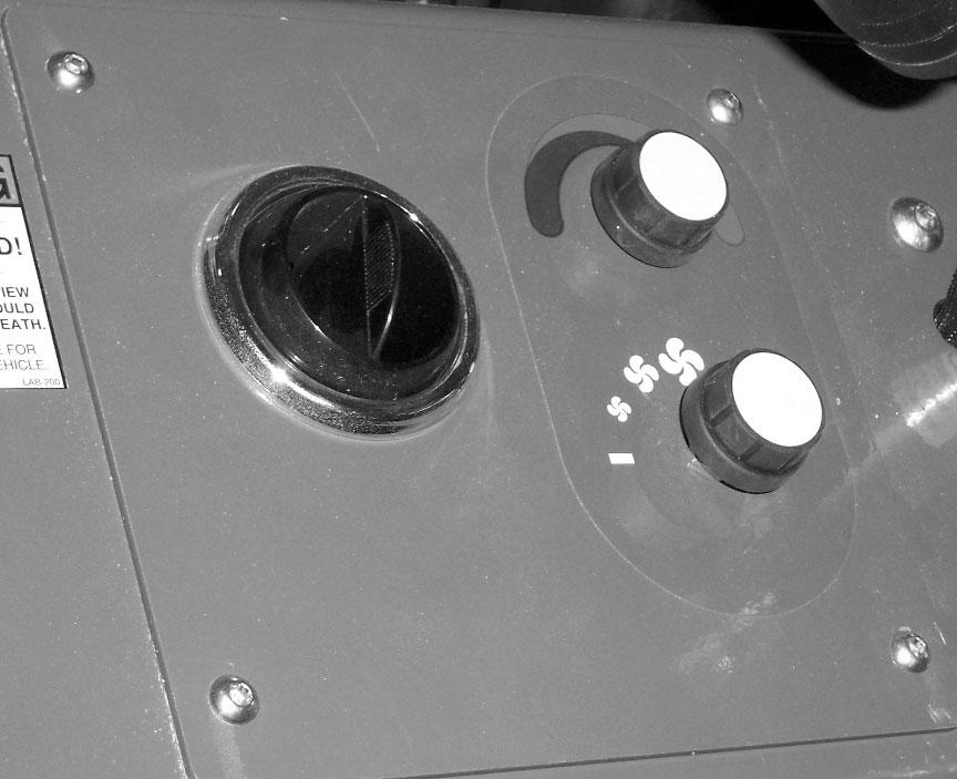
Heater Controls
Temperature Control: This is the upper knob located to the left of the steering wheel. This knob is used to adjust the temperature output of the heater. Turning the knob clockwise will increase the temperature output of the cab heater.
Fan Speed: This knob is located below the temperature control knob. Rotating the knob clockwise will increase the fan speed for increased air circulation.
Travel Lever
Located on the left side of the steering wheel column, this lever is used to change travel direction (forward or reverse) and speed.
Travel Direction: The lever MUSTbe in “N” (Neutral) position before the starter will engage to start the engine.
NOTE: Backup alarm automatically sounds with travel lever in “R” (Reverse).
Position “F” (Forward)
Position “N” (Neutral)
Position “R” (Reverse)
Speed Range: Twisting the lever end clockwise or counter-clockwise will change the transmission speed between low, medium and travel ranges.
Position “3” (Travel Range)
Position “2” (Medium Range)
Position “1” (Low Range)
IMPORTANT: Care should be taken when downshifting or changing direction, because damage to the transmission can occur if shifting is forced or attempted at too high a speed. Allow engine speed to slow before any downshift or directional change is attempted.
Steering
Turn the steering wheel to the right or left to turn the machine in that direction.The power steering system is designed to provide low effort steering without shock reaction from the axle wheels to the steering wheel.
Floor And Seat Area
Throttle Pedal: This pedal, operated by the right foot, controls the engine speed to match power requirements. Pushing down on the pedal increases engine speed; letting up on the pedal decreases engine speed.
Service Brake Pedal: Pressing this pedal activates inboard hydraulic wet-disc-type brakes on all four wheels. Separate front and rear brake systems allow bringing the machine to a safe stop if either system loses pressure.
Brake Fluid Reservoirs: Located under the hinged cover on the cab floor directly in front of the seat.
Seat Positioning: The seat is mounted on rails for forward and rearward repositioning, for comfort and to accommodate the operator’s size. Aspring-loaded latch handle under the front of the seat actuates the adjustment mechanism.
Suspension Seat Option: This option is avalable for addtional operator comfort. It is adjustable for a soft or firm ride.
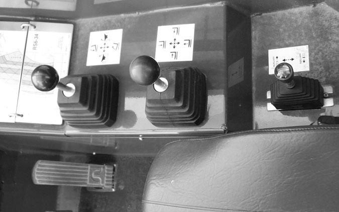
Right Side Panel
These controls and indicators are used to position the frame, boom and attachment. Graphic symbols on the side panel indicate the control actions and effect.
This machine is equipped with one of two types of boom and attachment joystick control configurations, either a two-joystick configuration, or a single tri-function joystick.
Warning
Use extreme caution when raising or extending the boom. The Telescopic Handler MUST be level. Loaded or empty, the machine can tip over if it is not level.
ALWAYS place the transmission in neutral, apply the parking brake and keep the service brakes fully applied before raising or extending the boom.
NEVER exceed the specified lift and reach capacities of the machine, or serious machine damage and personal injury may result. Refer to the load charts in the operator’s station or this manual.
If a boom circuit hose fails with the boom up, with or without a load, shut down the machine following the MANDATORYSAFETYSHUTDOWN PROCEDURE. DO NOT attempt repairs. Instead, call your Gehl dealer for assistance.
The truss boom and winch attachment tools should ONLYbe used to lift and place loads when the machine is in a stationary position. DO NOT use to transport loads around the jobsite. This can cause the load to swing, resulting in either the load dropping or the machine tipping over.
NEVER use winch for lifting or moving personnel. NEVER exceed the maximum rated capacity of the winch (3000 lbs./1360 kg) or exceed the load chart rating for winch applications.
DO NOT tilt the truss boom back more than 45o from horizontal. DO NOT attempt to use the optional rotating carriage as a load leveling function. ALWAYS level the frame prior to raising a load.
Failure to heed could result in death or serious injury.