
35 minute read
Swiveling the Boom

Warning
Working with the boom swiveled to the side reduces lifting capacity.
Overloading the bucket can cause an unstable condition and increase the possibility of tipping the machine.
The excavator boom can be swiveled from the front position 55º to the right and 75º to the left. This allows excavation of trenches along walls, fences, etc. See Figure 3-33.

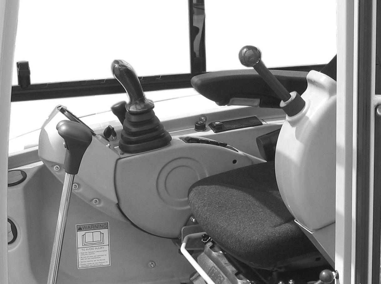
Press and hold the auxiliary control button (1, Figure 334), located on top of the left joystick. Then press the auxiliary hydraulics pedal (2) with your toe or heel. Pressing and holding the auxiliary hydraulic/changeover button (1) and pressing the front of the auxiliary hydraulics pedal (2) swiveled the boom to the left. Pressing and holding the auxiliary hydraulic/changeover button (1) and pressing the back of the auxiliary hydraulics pedal (2) swivels the boom to the right.

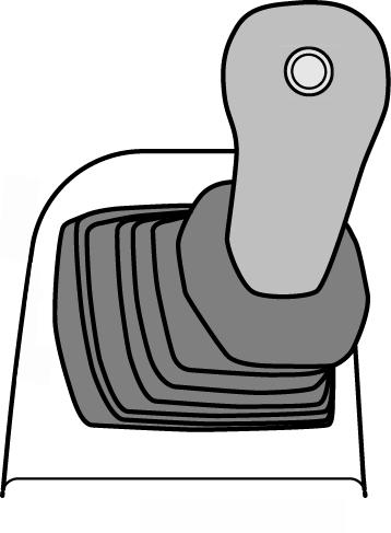
Note: Bucket controls do not change when swiveling the boom.
When the auxiliary hydraulic/changeover button is pressed and boom swivel is enabled, indicator (3) is lit.
Excavating
The following section applies to an excavator with a standard bucket, which is used mainly for digging into the ground to loosen, excavate and load loose or solid material.
Important
Never use the excavator bucket to perform actions other than digging, grading, loading and excavating. Damage to the excavator could result.
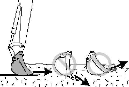
•Do not use the swiveling force of the excavator so the bucket serves as a hammer or battering ram (1, Figure 335).

•Do not lower the bucket into the ground while rotating the upper carriage or driving the excavator (2, Figure 3-36).
•Do not use the falling force of the dipper arm so the bucket serves as a hammer or pile-driver (3).
•Do not cause the excavator to tip, bounce or fall to amplify digging or excavating (4) force.
•Use caution when retracting the bucket to prepare for driving or transport. Hitting the bucket into the dozer blade might damage either attachment, especially the bucket teeth.
•The dozer blade is intended for grading only; using it as a battering ram risks serious damage to the blade, its cylinder and connections.
•When excavating, lower the dozer blade to the ground to aid machine stability. It is best to position the dozer blade on the same side as the excavation, but position the blade on the opposite side of the excavation if the situation prevents the former.
Digging
Proper Bucket Position
Move the flat side of the bucket so it is parallel to the ground (Figure 3-37).
Important
Positions 2 and 3 in Figure 3-37 show improper positions for using the bucket. Position 2 forces the bucket downward into the ground, slowing down work and subjecting the engine and hydraulic pump to overloading. Position 3 forces the bucket upward toward the ground surface, reducing productivity because of smaller loads being dug.

4.After the bucket is sufficiently filled: a.Continue moving the dipper arm toward the excavator, b.Extend the dipper arm cylinder so the bucket is tilted upward (6, Figure 3-38). c.Raise the boom.
Proper Digging Technique
1.Lower the bucket into the ground (4, Figure 3-38).
2.After the bucket penetrates the ground, adjust it so its flat side is parallel to the ground (5, Figure 338).
3.Pull the bucket towards the excavator by: a.Moving the dipper arm toward the excavator, and b.Lowering the boom.
Trench Excavating
Trench excavating is most efficient when the machine tracks are parallel to the line of the trench (Figure 339). For larger trenches, excavate each side first and then the center.
When trench excavating is needed in confined areas, the excavating can be done by rotating the upper carriage and swiveling the boom (Figure 3-40).

Loading Vehicles
When loading vehicles, consider the following:
•Whenever loading in a confined area with a limited range of motion, position the truck so maximum visibility is ensured for the excavator operator.
•When work conditions permit, position the truck so the excavator can load material at the rear of the truck instead of the sides (1, Figure 3-42). The most effective way to load into the rear of the truck is when the truck and excavator form a 45° angle (2, Figure 3-42).
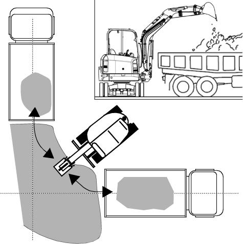
•Raise the boom and dipper arm to dump height just before rotating toward the truck.
•Whenever possible, dump upwind to keep dust and airborne debris away from the operator, and the excavator air filters and fans.
Figure 3-40 Excavating Trenches Sideways
•Working alongside trenches and deep excavation are two applications where the dozer blade might restrict bucket movement. When working alongside trenches, lower and place the dozer blade on the ground to avoid damage to the boom cylinder. When deep excavating, position the machine so the lowered dozer blade is on the opposite side of the excavation (Figure 3-41).
Warning
Placing the dozer blade on the opposite side of the excavation decreases machine stability. Always consider operator safety when operating the machine, especially when less-than-ideal working conditions.
Grading
Bulldozing
Warning
•Be sure there is proper clearance for the front end attachments when bulldozing.
•Be sure that the front end attachments do not contact overhead power lines or obstructions during bulldozing.
•DO NOT drive the machine into the excavation or onto loose soil, which can cause an unstable condition, and could possibly tip the machine.
1.Raise or lower the dozer blade using the control lever located to the right of the travel levers/pedals. See Figure 3-43. Move the lever forward to lower the dozer blade, rearward to raise the dozer blade.
2.The boom must be fully raised and the bucket curled in (up) when grading.
3.When grading, the material may be pushed away to the front or the side.
4.Raise the dozer blade slightly if excessive resistance occurs.
5.When the blade is in position, use the travel controls to move the machine as in normal travel.

Mounting/Removing Buckets
ALWAYS wear protective goggles, helmets, gloves, steel-toed shoes, etc.
DO NOT service the bucket while the engine is running.
DO NOT stand behind the bucket when removing the pins.
DO NOT use your hands or fingers to align the bucket and dipper arm holes.
ALWAYS verify the bucket is safely locked before starting the engine and resuming operation.
Warning
•DO NOT use a hammer directly on a securing pin to loosen it. The pounding may cause splintering, which may lead to serious injury.
•The bucket can crush hands or feet. DO NOT use your hands or feet as substitutes for the correct equipment.
Removing A Bucket
1.Lower the bucket to the ground with the flat side facing down (1, Figure 3-44).
Important
Place the bucket against the ground with minimum pressure. More pressure increases resistance, which will make it more difficult to remove the pins.
2.Stop the engine.
3.Remove the two lynch pins (2A and 2B, Figure 344).
4.Remove the lower securing pin first (3B, Figure 344) and then the other (3A). Carefully remove the pins with a hammer and brass punch if they are stuck. Once pin 3B is removed, pin 3A might have more pressure applied against it, making it difficult to remove. If this happens: a.Start the engine. b.Slightly raise and lower the boom to relieve pressure from the pin. c.Turn off the engine. d.Try removing the pin again, using a hammer and brass punch if needed.
Attaching A Bucket
1.Grease the dipper arm and bucket holes.
2.Since the bucket is on the ground and stationary, maneuver the machine until the dipper arm holes align flush with the bucket holes.
Warning
DO NOT use your hands or fingers to align the bucket and dipper arm holes.
3.Stop the engine.
4.Insert the upper securing pin first (3A, Figure 344). If needed, use a hammer and brass punch to gently tap the pin through the hole. Insert a lynch pin (2A, Figure 3-44) through the hole in the pin and lock.
Important
The flat side of each securing pin head must align with the flat guide on each side of the hole; see 3A and 3B in Figure 3-27 for how the pins look when properly installed.
5.Insert the lower securing pin (3B, Figure 3-44). If needed, use a hammer and brass punch to gently tap the pin through the hole. Insert a lynch pin (2B, Figure 3-44) through the hole in the pin. Lock the lynch pin securely in place.
6.Verify the bucket is locked and secure before starting the engine and resuming operation.

Auxiliary Hydraulics Connections
Important
Follow the instructions in the operator’s manual from the attachment manufacturer for connecting the attachment to the machine’s auxiliary hydraulics.
7.To connect each coupling: a.If necessary, rotate lock sleeve (2, Figure 3-46) so notch (3) aligns with lock ball (4). b.Pull lock sleeve (2) down in the direction of arrow (5). c.Insert the attachment coupling into the corresponding auxiliary hydraulics connection coupling.
Figure 3-45 shows the three quick connections on the dipper arm meant for auxiliary hydraulics, which are for the following:
• 1: Pressure line (male connector)
• 2: Large return line (female connector)
• 3: Pressure line (female connector) d.Release lock sleeve (2) so it snaps into place and locks the couplings together. Verify the lock sleeve (2) is snapped closed and the coupling is securely locked together. e.Twist lock sleeve (2) so notch (3) is NOT aligned with lock ball (4), to help prevent accidental de-coupling.
Disconnecting the Quick Couplings
1.Perform steps 1 through 6 in “Connecting the Quick Couplings” on page3-30 before proceeding to the next step.
2.To disconnect each coupling: a.Pull lock sleeve (2, Figure 3-46) down in the direction of arrow (5). b.Listen for the hissing sound to verify that any pressure has been released from the connection. c.Twist lock sleeve (2) so notch (3) is aligned with lock ball (4).
Figure 3-45 Auxiliary Hydraulics Connections
Connecting the Quick Couplings
1.Park the machine on firm and level ground.
2.Extend the dipper arm cylinder halfway and position the boom/dipper arm so the auxiliary hydraulic connectors are positioned as shown in Figure 3-45.
3.Stop the engine.
4.Turn the ignition key to position 1.
5.Release pressure from the bucket cylinder by moving the left control lever to the left and right.
6.Lift the left control lever base as a safety precaution.
d.Push lock sleeve (2) up in the direction of arrow (6) to disconnect the coupling.
Warning
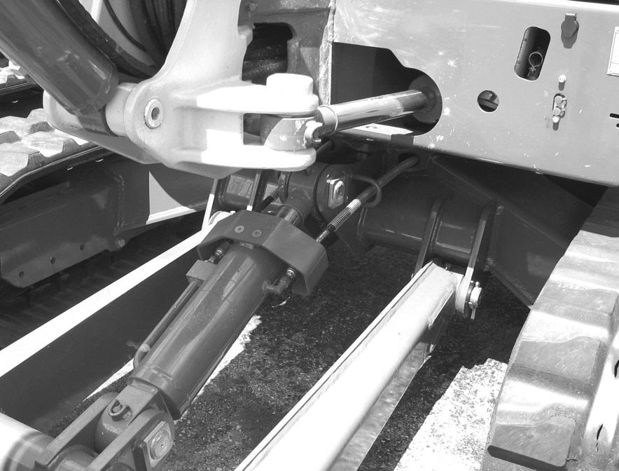
•When towing the machine, make sure no one is close to the towing apparatus, or in between the vehicles. The machine may only be towed using suitable towing equipment, in connection with suitable towing apparatus, such as a towing coupling, hooks and eyes.
•Do not use a towing apparatus that is kinked, twisted, or otherwise damaged.
•Do not apply high loads abruptly to the retrieval apparatus. The towing bracket has a maximum admissible load of 5238 lbf (2330 daN).
•The towing bracket is designed for retrieving the machine only. Do not use the excavator to tow other vehicles.
•Do not tow the machine if the travel drive is damaged. Damage to the machine cause by towing is not covered under warranty.
The excavator can be towed by using the towing bracket (1, Figure 3-47). Secure a towing shackle, shackle pin and lock (2) of adequate size to the towing bracket (1) as shown. Tow the machine slowly and only short distances.


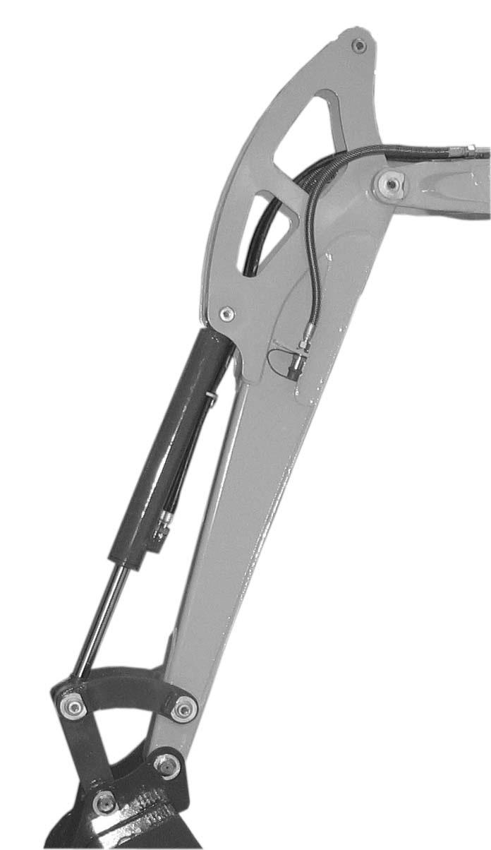
Lifting the Machine
Warning
•Use a lifting device and rigging with sufficient capacity for the weight of the machine plus any attachments.
•Maintain center-of-gravity and balance points on the machine. See Figure 3-48.
•Do not swing boom.
•Never lift machine with the operator aboard.
Secure the lifting fixture sling to the lifting points (1, Figure 3-48) on the machine as follows:
•length L1 on the lifting sling for the boom must be 6’3” (1.9 m) long.
•Length L2 on the lifting sling must be 10’4” (3.15 m) long.
Do not exceed rated load capacity of the lifting machine. See “General Specifications” on page1-9 for excavator weight.
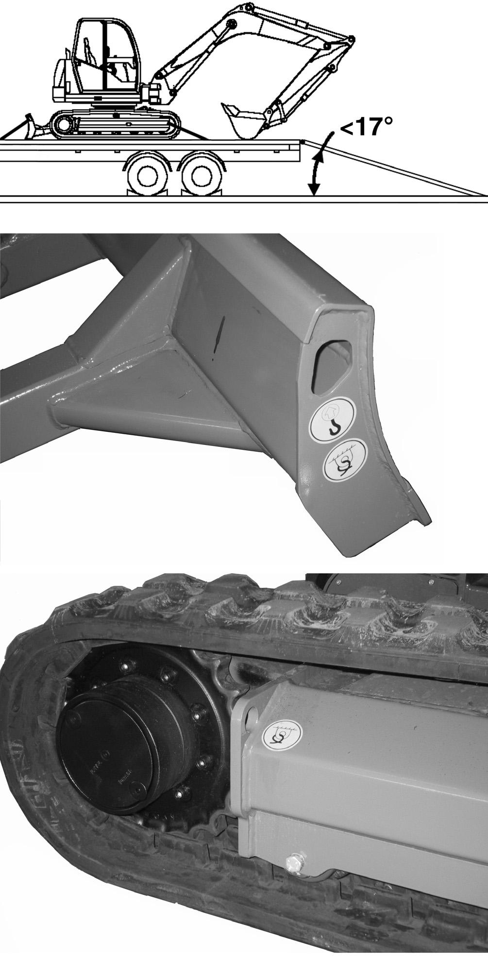
Loading and Transporting
Note: Refer to Figure 3-49.
Use only transporters that are in proper working order and are approved for use on public roads.
When using ramps to load the transporter:
•Do not exceed an incline of 17°.
•Clean dirt, mud, ice and snow from the ramps and tracks.
•Use metal loading ramps with a slip-resistant surface, and with beveled ends to prevent damage to rubber tracks.
Loading Procedure:
1.Attach ramps securely to the transporter to prevent them from slipping off during loading.
2.Load the transporter on solid, even ground.
3.Engage the transporter parking brake and chock the wheels.
4.Determine the direction of the track movement (blade facing forward) before moving the excavator onto the ramps.
5.After the excavator is on the transporter, lower the dozer blade and the bucket onto the loading surface and turn off the excavator engine.
6.Lock the cab.
7.Place chocks under the excavator tracks.
8.Secure the excavator to the transporter at the tiedown points (1, Figure 3-49) to prevent the excavator from slipping, overturning or moving during transport.
Note: The tie-down points on the excavator are identified by decals (1, Figure 3-49).
General Information Care And Servicing
Warning
Read and understand this entire manual before operating and/or servicing the machine. Follow warnings and instructions for operation and maintenance. Check for correct function after adjustments or maintenance. Failure to follow instructions can result in injury or death.
Warning
Be sure you are familiar with all safety devices and controls before operating or servicing the machine. Know how to stop before starting. The machine is designed for use only with approved accessories or referral attachments. Manitou Americas, Inc. cannot be responsible for safety if the machine is used with non-approved attachments.
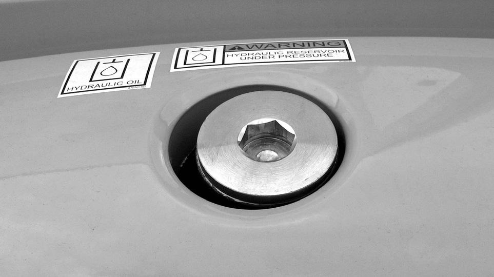
Warning
The hydraulic reservoir is under pressure. Avoid contact with leaking hydraulic fluid and diesel fuel under pressure because they can penetrate the skin and eyes.
Care and Servicing
The care and servicing of the machine has a significant influence on its operational readiness and service life.
Use of lubricants not corresponding to the manufacturer’s recommendations may invalidate warranty claims.
More frequent servicing, other than the recommended intervals, may be required under extreme conditions (extremely dusty or hot conditions).
Always dispose of waste lubrication oils and hydraulic fluids according to environmental laws or take to a recycling center for proper disposal. DO NOT pour fluids onto the ground or down a drain.
DO NOT power-wash the main hydraulic pumps and controls, throttle solenoids and sealed bearings. High pressure water can be forced through seals and trapped within these components, causing premature failure.
The operating pressure settings of the hydraulic system should only be adjusted by trained, qualified personnel. If malfunctions are caused by unauthorized alteration of operating pressure settings, all warranty responsibilities of the manufacturer are invalidated.
Maintenance Safety
•Never service the machine without reading the applicable instructions.
•Always lower bucket and dozer blade to the ground before performing any maintenance.
•Use correct procedures to lift and support the machine. Always lift the dozer blade fully before installing jackstands.
•Keep the engine cover and hydraulic valve covers closed except for service. Close and latch covers before operating the machine.
•Be sure to have the work area properly ventilated when grinding or welding parts. Wear a dust mask.
•Exhaust fumes can kill. Exhaust system must be tightly sealed. If working in an enclosed area, vent exhaust to outside if the engine must be run for service.
•Never perform unapproved modifications or add unapproved attachments.
•Stop the engine and let cool, then clean any flammable materials from the engine before checking fluid levels.
•Never service or adjust the machine with the engine running unless it is required by the service procedure.
•Avoid contact with leaking hydraulic fluid and diesel fuel under pressure. The pressurized fluids can penetrate the skin and eyes. NEVER use your hands to search for hydraulic fluid leaks — use a piece of paper or cardboard. Escaping fluid under pressure can be invisible if it penetrates the skin it can cause serious injury. If any fluid is injected into your skin, see a doctor at once. Injected fluid MUST be surgically removed by a doctor familiar with this procedure or gangrene may result.
•Never fill the fuel tank with the engine running, while smoking or when near open flame.
•Wipe up fuel spills immediately.
•Keep your body, jewelry and clothing away from moving parts, electrical contacts, hot parts and exhaust.
•Wear eye protection when servicing the machine.
•Lead-acid batteries produce flammable and explosive gas. Keep arcs, sparks, flames and lighted tobacco away from batteries.
•Batteries contain acid, which burns eyes and skin on contact. Wear protective clothing. If acid contacts body, flush well with water. For eye contact, flush well with water and get immediate medical attention.
Maintenance Label Symbols
Symbol Assembly Explanation
GeneralVisual check
GeneralGrease instructions
Fuel systemDrain condensation from fuel
Fuel systemReplace the fuel filter; clean the fuel pre-filter
RadiatorCheck the coolant level
RadiatorDrain and fill with new coolant
EngineCheck valve clearance; adjust if necessary
EngineCheck the engine oil level
EngineChange engine oil
EngineReplace the oil filter
EngineCheck V-belt tension
Travel driveChange oil
Travel driveCheck the oil
UndercarriageCheck track tension
Hydraulic systemCheck oil level
Hydraulic systemChange hydraulic oil
Hydraulic systemReplace the hydraulic oil filter; replace the breather filter
Radiator finsClean
Heating, air conditioning Replace the cab air filter
Maintenance Schedule
The following service schedule is a recommended. Maintenance work must be done at regular intervals. Failure to perform scheduled maintenance work will result in excessive wear and early machine failures. The following service schedule is a recommended.
clean/replace necessary a.After emptying the tank, water must be removed and air must be purged from the fuel system before use. See “Fuel Shut-off Valve and Water Separator” on page4-14 and “Purging Air from the Fuel System” on page4-14.
Check, Clean & Inspect (continued)
a.Check
Fluid and Filter Changes
a.Change after first 50 hrs; every 500 hrs thereafter.
b.Dusty work environment, high temperature, high rate of hammer use, and similar intensive use conditions.
c.Change after first 50 hrs; every 500 hrs thereafter.
d.Change after first 50 hrs; every 1000 hrs thereafter.
Daily Lubrication
(See Figure 4-1 and Figure 4-2)
Dipper
Chassis (front of undercarriage)xx

Lubricate daily at the points indicated

Lubricate daily at the points indicated

Recommended Lubricants
Engine Oil
Important
Be sure to read the engine manual supplied with this machine for detailed engine specifications.
See “Fluid Capacities/Lubricants” on page1-4 for proper engine oil specifications.
Hydraulic Oil
See “Fluid Capacities/Lubricants” on page1-4 for proper hydraulic oil specifications.
Swing Ring
Lubricate with a heavy-duty lithium complex grease with 3% molybdenum disulfide, such as Chevron RPM Heavy Duty Grease No. 2, Mobilgrease Moly 52 or BP Energrease Moly EP2.
Final Drive Unit
An EP grade gear oil that conforms to API GL5, such as Chevron Delo Gear 80-W90 or BP Transgear 80W90 is required.
Swing Gear Unit
An EP grade gear oil that conforms to API GL5, such as Chevron Delo Gear 80-W90 or BP Transgear 80W90 is required.
Lubrication Points
See Figures 4-1 and 4-2.
Apply a heavy-duty lithium complex grease with 3% molybdenum disulfide. See “Fluid Capacities/Lubricants” on page1-4 for more detailed specifications.
Ranges of Applications
From –4° F to +104° F (-20° C to + 40° C) outside temperature.
Engine
Checking Engine Oil Level
Important
See “Fluid Capacities/Lubricants” on page1-4 for engine oil grade. To prevent damage to the engine, only use the engine oils specified, or oils of equivalent quality and grade.
To check the engine oil, the machine must be on a level surface with the engine turned off. Check the oil level before starting the engine or at least five minutes after shutting off the engine.
1.Push the engine cover latch button and raise the engine cover.
2.Check the engine oil level using the dipstick (1) located on the right side of the engine. See Figure 4-3.
3.Add oil if required through the oil filler neck (3). See Figure 4-3.
4.Drain excess oil if required. See “Changing Engine Oil and Filter ” on page4-11
Note: Marks on the dipstick indicate the minimum and maximum oil levels.
Changing Engine Oil and Filter
1.Perform the “Mandatory Safety Shutdown Procedure” on page2-2, but do not allow the engine to fully cool; warm oil will drain more completely.
Important
The machine must be postioned on a level surface for the oil to drain completely.
2.Push the engine cover latch button and raise the engine cover.
3.Position a waste oil collection container under engine oil pan.
4.Remove the drain plug from the oil pan and allow the oil to drain into the waste oil collection container.
Important
Dispose of waste engine oil according to environmental laws or take to a recycling center for proper disposal. DO NOT pour waste engine oil onto the ground or down a drain.
5.Remove the oil filter, using a filter wrench as necessary. See (1) Figure 4-4.
6.Clean the filter housing surface. Put a film of clean oil on the filter gasket. Install the new filter and tighten 1/2 rotation past where the filter contacts the filter mounting surface.
7.Reinstall the drain plug.
8.Clean the area around the oil filler cap.
9.Remove the oil filler cap and raise the oil dipstick (2) slightly to allow any trapped air to escape.
10.Add new oil through the oil filler cap opening. Crankcase capacity with filter is approimately 7.5 qts. (7.1 L). Do NOT fill crankcase above the MAX mark on the dipstick.
11.Reinstall oil filler cap.
12.Wait about 3 minutes to allow the oil to run into the oil sump and check the oil level according to “Checking Engine Oil Level ” on page4-10.
13.Start the engine and let it run for several minutes. Watch the engine oil light on the control panel. The light should turn off after several seconds. If it does not, shut off the engine, determine the cause and fix the problem before restarting the engine.
14.Stop the engine and check for leaks at the oil filter and oil drain plug.
15.Check the oil level again and add oil if necessary.
Air Cleaner
1.Perform the “Mandatory Safety Shutdown Procedure” on page2-2, but do not allow the engine to fully cool; warm oil will drain more completely.
2.The air cleaner is located under the engine cover. Press the engine cover release button and raise the engine cover.


3.Release the bow clips (1) to remove the air cleaner cover and gasket (2). See Figure 4-5.
4.Carefully remove outer air cleaner element (3). See Figure 4-5. Carefully remove inner air cleaner element (3). Clean the inside of the air cleaner housing components with a lint-free cloth. Clean all contamination, dirt and dust from inside the upper and lower air cleaner housing and cover.
5.Replace both the inner and outer air cleaner elements when the indicator light comes on. See “Fluid and Filter Changes ” on page4-6.

6.Reinstall air cleaner elements (3, 4), gasket and air cleaner cover (2). Fasten bow clips (1).
7.Close and secure engine cover.
Important
Do not knock the element against a solid object to remove dust. The element may become distorted and damaged.
Important
Do not operate engine without the air cleaner components installed or damage to the engine could occur.
Fuel System
Filling the Fuel Tank
Warning
Stop the engine and allow it to cool before filling the fuel tank. NO SMOKING! Failure to obey warnings can cause an explosion or fire.
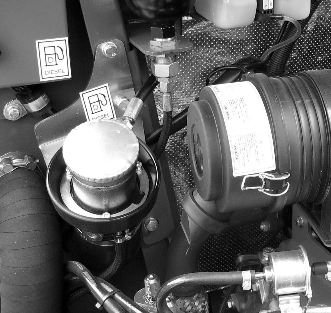
The fuel level in the tank is indicated by the fuel gauge (1) on the console. See Figure 4-6.
The fuel tank inlet is located inside the engine compartment. To fill the tank, push the engine cover latch button, raise the engine cover and remove the fuel filler cap (2). See Figure 4-6. Fill the fuel tank with clean diesel fuel with a cetane rating over 45. After fueling, re-install fuel cap, and close and latch the engine cover.
Important
Unless draining fuel tank for servicing, never operate the machine until the fuel tank is completely empty. The fuel system has to be bled of air whenever the fuel tank is run empty. Always fill the fuel tank after use.
Important
When using the machine in cold weather, it is important to use the proper fuel blend to prevent the fuel “gelling”. See the engine operator’s manual for fuel blend infomation related to temperature. Fuel gelling can permanently clog the fuel filter and water separator elements, requiring replacement.
Warning
Always clean up spilled fuel and oil. Keep heat, flames, sparks and lighted tobacco away from fuel and oil. Failure to use care around combustibles can cause explosion or fire, which can result in injury or death.
Danger
When handling fuel, there is a high risk of fire. Never work on the fuel system around open flames or sparks. DO NOT smoke when working on the fuel system or refueling. Before refueling, turn off the engine and remove the ignition key. Do not refuel in closed rooms. Wipe up fuel spills immediately. Keep the machine clean to reduce the risk of fire.
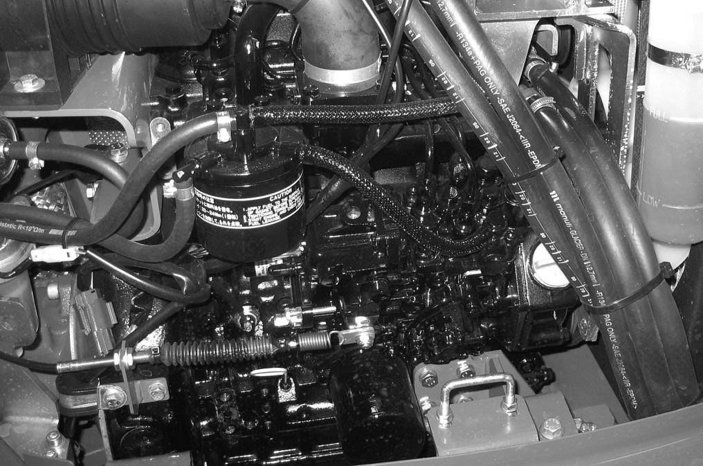
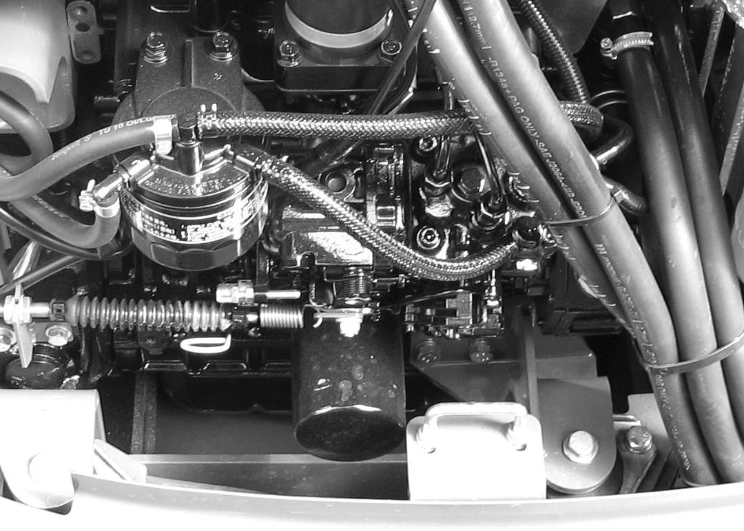
Fuel Filter
Warning
Use care to catch any spilled fuel when servicing the fuel filter. Spilled fuel can cause a fire.
The fuel filter is located approximately mid-way between the engine oil filter and the air cleaner.
1.Before servicing the fuel filter, perform the “Mandatory Safety Shutdown Procedure ” on page2-2.
1.Twist the fuel shut-off valve lever (2, Figure 4-8) on the water separator to the “OFF” position, as shown.
2.Clean dirt from the housing and unscrew the fuel filter (1, Figure 4-7).
3.Remove and discard the old fuel filter properly.
4.Clean around the filter housing.
5.Coat the seal on the new fuel filter with clean engine oil.
6.Install the new fuel filter and tighten 1/2 rotation past where the filter contacts the filter mounting surface.
7.Twist the fuel shut-off valve (2, Figure 4-8) on the water separator to the “ON” position.
The fuel system must be purged of air after changing the fuel filter, or if the fuel tank has been run dry. See “Purging Air from the Fuel System” on page4-14.
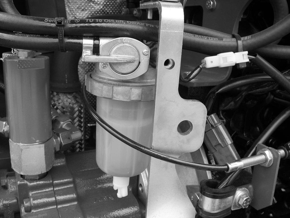
Fuel Shut-off Valve and Water Separator
If water is seen in the water separator bowl or the indicator ring rises to position (4, Figure 4-8), the bowl will need to be drained.
Note: The water separator is located on the engine below the air cleaner.

1.Twist the fuel shut-off valve lever (2) on the water separator to the “II” (OFF) position, as shown.
2.Unscrew plug (3) and collect the water that drains out of the water separator. Allow water to drain until the indicator ring reaches the bottom of the water separator.
3.Tighten plug (3) and discard fuel/water according to environmental laws. DO NOT pour fluids onto the ground or down a drain.
4.Twist the fuel shut-off valve (2) on the water separator to the “I” (ON) position.
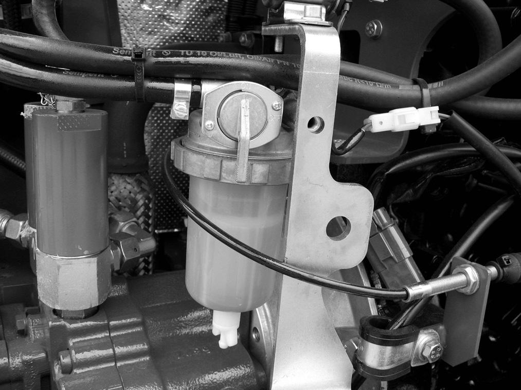
Purging Air from the Fuel System
Warning
DO NOT bleed air on a hot engine. Spilled fuel can cause a fire.
Starting from the fuel tank, the fuel system runs through the water separator, fuel filter, fuel injection pump and high pressure piping to the fuel injection nozzles. If the fuel tank is run dry, or if the fuel filter, water separator or fuel lines are replaced, trapped air must be removed, or bled, from the fuel system.
Bleed air from the fuel system according to the following steps:
1.Fill the fuel tank.
2.Make sure that the valve on the water separator valve (1, Figure 4-9) is in the “ON” position.
Cooling System
Checking Coolant Level
Note: The engine must be cold.
1.Press the engine cover release button and raise the engine cover.
2.Check the coolant level in the expansion reservoir. If the coolant level is low (2, Figure 4-10), remove the reservoir cap and overflow tube.
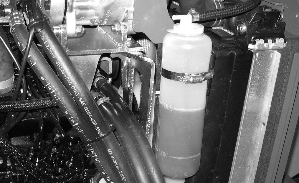
3.Fill reservoir to FULL line (1). Refer to “Fluid Capacities/Lubricants” on page1-4 for the correct coolant type and to “Coolant Compound Table” on page1-8 for the correct coolant mixture. Replace the reservoir cap.
3.Turn the ignition key to the “I” (ON) position.
4.Wait about five minutes while the fuel system bleeds itself.
5.Start the engine.
If the engine runs smoothly and then stops, or if it does not run smoothly, switch off the engine and bleed the system again as described in this procedure. If the engine still does not run smoothly, contact your dealer.
Electrical System
Warning
Inspect and check the machine’s electrical equipment at regular intervals. Defects, such as loose connections or scorched cables much be repaired before using the machine. Work on the machine’s electrical system must be done only by a trained technician.
Fuses
The fuse panel (1, Figure 4-11) is located in the side of the kick panel, below the seat.
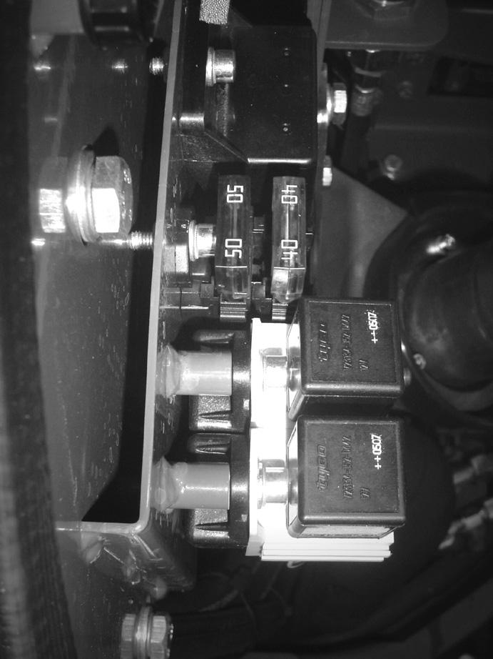
The main fuse (2) is located in the electrical box in the upper left engine compartment. See “Main Fuse Box with Relays” on page1-7.
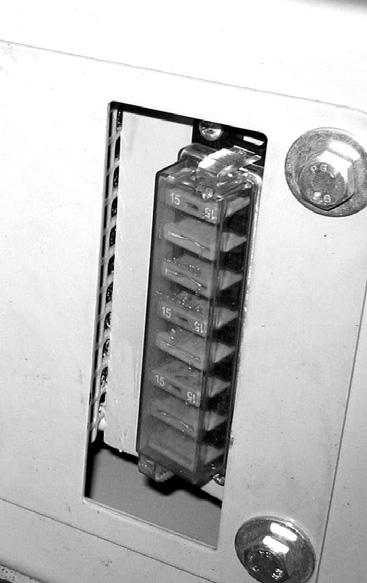
To replace a fuse, remove the panel cover and pull the old fuse from the socket. Install a new fuse of the same rating and re-install the fuse panel cover.
Important
Blown fuses indicate electrical system malfunctions. Determine what caused the fuse to blow and repair the problem before replacing the fuse.
Note: Additional fuse identification information can be found on pages 1-7 to 1-8.
Battery
Warning
Before servicing the battery or electrical system, disconnect battery from the electrical system by turning the battery disconnect switch to the “OFF” position.
Explosive gas is produced while a battery is in use or being charged. Keep flames or sparks away from the battery area. ALWAYS charge the battery in a wellventilated area. Do not jump-start a frozen battery, or it may explode. A discharged battery can freeze at 14°F (10°C).
To prevent short circuits keep metal parts on your clothing and metal watchbands away from the positive (+) terminal of the battery.
Warning
Never lay a metal object on top of a battery, because a short circuit can result. Battery acid is harmful to skin and fabrics. If acid spills, follow these first-aid tips:
Immediately remove any clothing on which acid spill.
•If acid contacts skin, rinse the affected area with running water for 10 to 15 minutes.
•If acid contacts eyes, flood eyes with running water for 10 to 15 minutes. See a doctor at once. Never use any medication or eye drops unless prescribed by the doctor.
•To neutralize acid spilled on the floor, use one of the following mixtures:
•0.5 kg (1 lbs.) of baking soda in 4 L (4 qts.) of water.
•0.5 L (0.5 qts.) of household ammonia in 4 L (4 qts.) of water.
In case of acid contact, wash immediately with water for several minutes. In case of eye contact, get medical attention immediately.
The battery is located under the cab near the rear of the undercarriage. See 1, Figure 4-12. Refer to “Tilting the cab or canopy” on page3-10 for how to tilt and secure the cab to gain access to the battery.
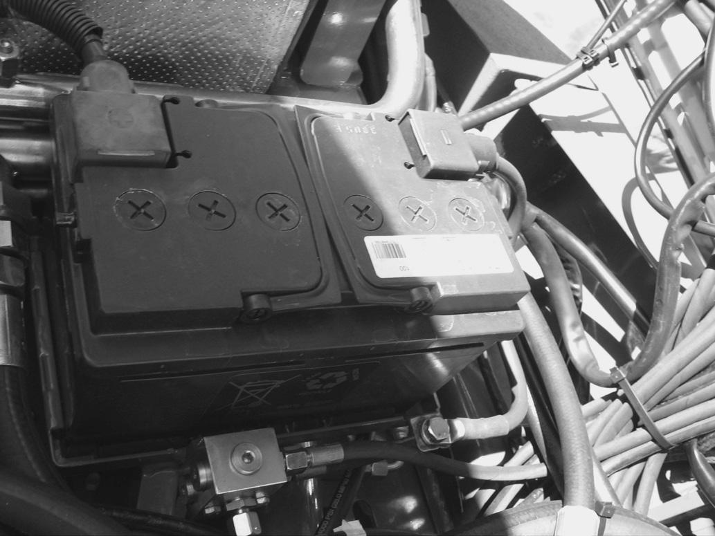
Battery cables must be clean and tight. Remove any acid or corrosion from the battery and cables using a sodium bicarbonate and water solution. Cover the battery terminals and cable ends with battery-saver grease.
Note: The battery is maintenance-free and requires no other service.
Using a Booster Battery (Jump-Starting)
Warning
•Keep arcs, sparks, flames and lighted tobacco away from batteries. When jump-starting from a booster battery, make final connection (negative) at engine frame away from the battery. Batteries can create flammable gases. Sparks or open flames can cause this gas, and the battery, to explode.
•DO NOT jump-start or charge a frozen battery. Warm battery to 60°F (16°C) before connecting to a charger. Unplug charger before connecting or disconnecting cables to battery.
Important
When jump-starting from another machine, be sure the second machine is not running if the glow plugs are used on unstarted machine. High voltage spikes from a running machine can burn out the glow plugs.
Important
Damage to the alternator can occur if:
•the engine is operated with the battery cables disconnected,
•the battery cables are connected when using a fast charger or when welding on the machine (When welding on the machine, remove both cables from the battery and ground the welder to the machine frame near the repair area), or
•battery booster cables are connected incorrectly.
Important
The booster battery must be 12 volt.
Jump-start Procedure:
1.Turn ignition key on the machine with the discharged battery to the “P” position.
2.Open the engine cover.
3.Connect one end of a jumper cable to the positive (+) terminal on the booster battery.
4.Connect the other end of the same cable to the positive (+) terminal on the battery disconnect switch (1, Figure 4-13) of the machine with the discharged battery.
5.Connect one end of the second jumper cable to the negative (-) terminal on the booster battery.
6.Connect the other end of the same cable to the frame of the machine with the discharged battery.
Start the engine of the machine with the discharged battery. Once the engine is running, remove the cable connected to the frame first. Disconnect the other cable from the positive (+) terminal on the battery disconnect switch. Remove the cables from the booster battery last.
Important
DO NOT allow the booster cable ends to touch when removing them from the batteries. Arcs and direct short circuits can cause severe damage to electrical components.
Hydraulic System
Warning
The hydraulic reservoir is under pressure. Never use your hands to search for hydraulic fluid leaks; use a piece of paper or cardboard to find leaks. Escaping fluid under pressure can be invisible and can penetrate the skin, causing serious injury. If any fluid is injected into your skin, see a doctor at once. Injected fluid MUST be surgically removed by a doctor familiar with this procedure, or gangrene may result.

Checking Hydraulic Oil Level
1.Position the machine on a level surface.
2.Fully extend the bucket and boom, retract the arm and position as shown in Figure 4-14.
3.Lower the bucket and dozer blade to the ground. Move the joysticks in all directions to verify the hydraulic system is de-pressurized.
4.Shut off the engine. Remove the ignition key and take it with you. Lock out the controls by raising left control console.
Note: A short hex shaft is included in the tool kit. This tool is designed to be used with a standard ratchet wrench to open the filler cap.
c.With the filter insert (5) in place, add hydraulic oil until the oil level is between the marks on sight gauge (1).
Figure 4-14 Excavator Position for Checking and Changing Hydraulic Oil
5.Check the hydraulic oil level sight gauge (1, Figure 4-15). Oil level should be approximately at the point shown at (2).
6.If the hydraulic oil level is low: a.Open the engine cover. b.Slowly loosen the breather cap (3) with a cloth to relieve pressure. Re-tighten the breather cap after relieving pressure. Slowly open the hydraulic oil filler cap (4) and then remove the cap. d.Re-install the hydraulic oil filter insert and filler cap and tighten them securely. e.Start the engine and let it idle for a few minutes. f.Check hydraulic functions. Repeat this procedure to recheck the hydraulic oil level. Add oil if necessary.


Changing Hydraulic Oil
1.Position the machine on a level surface.
2.Fully extend the bucket and boom, retract the arm and position as shown in Figure 4-14.
3.Lower the bucket and dozer blade to the ground. Move the joysticks in all directions to verify the hydraulic system is de-pressurized.
4.Shut off the engine. Remove the ignition key and take it with you. Lock out the controls by raising left control console.
5.Slowly loosen the breather cap (3) with a cloth to relieve pressure. Re-tighten the breather cap after relieving pressure. Slowly open the hydraulic oil filler cap (4). Remove the cap and the filter insert (5).
Important
The filler cap and filter assembly will be removed over the rear cover. Protect the rear cover from spilled or dripping hydraulic fluid.
6.Open the reservoir drain plug and drain the oil into a suitable container. Re-install the drain plug and tighten securely.
Important
Always dispose of hydraulic fluids according to environmental laws or take to a recycling center for proper disposal. DO NOT pour onto the ground or down a drain.
7.Reinstall filter insert (5).
8.Fill the reservoir with hydraulic oil until oil level is between marks on sight gauge.
9.Re-install the hydraulic filler cap (2) and tighten securely.
10.Start the engine and let it idle for a few minutes. Cycle all front attachment hydraulic functions and check the hydraulic oil level according to “Checking Hydraulic Oil Level” on page4-19.
Hydraulic Cooling System
The hydraulic system uses a hydraulic cooler to keep the hydraulic fluid at the proper temperature. The cooler is located inside the engine compartment near the engine radiator. Inspect the cooler for leaks or damage.
Pilot Valve
Important
Hydraulic oil contamination can damage pilot valve control spools. Check the pilot control valve filter/restrictor every 1000 hours (every other oil change) and clean if necessary. Replace the filter/restrictor if it is damaged in any way.
Checking Pilot Control Valve Filter:
1.Position the machine on a level surface.
2.Fully extend the bucket and boom, retract the arm and position as shown in Figure 4-14.
3.Lower the bucket and dozer blade to the ground. Move the joysticks in all directions to verify the hydraulic system is de-pressurized.
4.Shut off the engine. Remove the ignition key and take it with you. Lock out the controls by raising left control console.
5.To relieve pressure, slowly loosen the breather cap (3) with a cloth. Re-tighten the breather cap after relieving pressure.
6.Tilt the cab/canopy according to “Tilting the Cab or Canopy” on page3-10.
7.Disconnect hose (A, Figure 4-16) connected to the pilot control filter/restrictor fitting (B) on the side of a joystick control valve.
Important
Hydraulic oil will leak during procedure. Place absorbent material under valve to catch leaking oil. Always dispose of hydraulic fluids according to environmental laws or take to a recycling center for proper disposal.
8.Disconnect the pilot control filter/restrictor fitting (B) from the valve.


9.Check the filter/restrictor fitting filter screen (C) for contamination/dirt and clean if necessary. Replace the filter/restrictor if it is damaged.
10.Replace filter/restrictor fitting (B) back into the valve, and reconnect hose to the filter/restrictor (C). Tighten securely.
11.Repeat steps 7-10 for the other joystick control valve.
12.Tilt the cab/canopy down according to “Tilting the Cab or Canopy” on page3-10.
Warning
•Hydraulic hoses and connections must be inspected by a trained technician before the first use of the machine, and at least annually thereafter, for leaks and/or damage.
•Leakages and damaged pressure lines must be immediately repaired or replaced by an authorized service center.
•Never use your hands to check for suspected hydraulic leaks. Always use a piece of wood or cardboard.
•Leaks from hydraulic hoses or pressurized components can be difficult to see, but pressurized oil can have enough force to pierce the skin and cause serious injury.
•Obtain immediate medical attention if pressurized oil pierces the skin. Failure to obtain prompt medical assistance could result in gangrene or other serious damage to tissue.
•Always relieve hydraulic system pressure before performing any maintenance on the machine. Do not tighten leaking connections when the hydraulic system is under pressure.
•Never weld or solder damaged or leaking pressure lines and/or screw connections. Always replace damaged hydraulic components.
•Hydraulic hoses must be replaced every six years from the date of manufacture, even if they do not appear damaged. The date of manufacture (month or quarter and year) is indicated on hydraulic hoses. See Figure 4-17.

Checking and Adjusting V-belt Tension
1.Position the machine on a level surface.
2.Lower the bucket and dozer blade to the ground. Move the joysticks in all directions to verify the hydraulic system is de-pressurized.
3.Shut off the engine. Remove the ignition key and take it with you. Lock out the controls by raising left control console. Wait for the engine to cool down.
4.Press the engine cover release button and raise the engine cover. Carefully inspect the V-belt (1) for damage. If the V-belt (1) is damaged, have it replaced by your dealer.
5.Press on the center of a span on the V-belt to check deflection. The belt deflection should be no more than 5/16” (8 mm). See Figure 4-18.
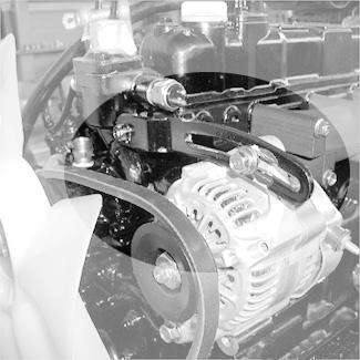
6.If deflection is more than 5/16” (8 mm): a.Loosen adjustment bolt (2) and rotate the alternator (3) in the direction of the arrow until Vbelt tension is correct. b.Tighten adjustment bolt (2) and re-check Vbelt tension.

Checking and Adjusting Air Conditioning V-belt Tension

1.Position the machine on a level surface.
2.Lower the bucket and dozer blade to the ground. Move the joysticks in all directions to verify the hydraulic system is de-pressurized.
3.Shut off the engine. Remove the ignition key and take it with you. Lock out the controls by raising left control console. Wait for the engine to cool down.
4.Press the engine cover release button and raise the engine cover. Carefully inspect the air conditioning V-belt (1) for damage. If the V-belt (1) is damaged, have it replaced by your dealer.
5.Press on the center of a span on the air conditioning V-belt to check deflection. The belt deflection should be no more than 3/8” (9 mm). See Figure 419. If deflection is more than 11/32” (9 mm): a.Loosen bolt (2) and pull down on the belt tensioner (3) until the correct V-belt tension is correct.

Track System
Track Cleaning
If dirt or mud builds up in the track frame, raise the track frame using the boom and dipper arm and then rotate the elevated track to clean it. Be sure that the build-up has been cleared from the track. Repeat for the other track. See Figure 4-20.
5.Shut off the engine. Remove the ignition key and take it with you. Lock out the controls by raising left control console.
6.Remove both screw plugs. Pour fresh oil (Chevron Delo Gear 80-W90 or BP Transgear 80-W90) into the top hole until oil starts to run out of the bottom hole.
7.Re-install both plugs securely.
Note: When using the boom and dipper arm to lift any portion of the machine, roll the bucket until the round base is against the ground. The angle of the arm to the boom should be at 90º. See Figure 4-20.
Changing Final Drive Oil
1.Position the machine on a level surface with final drive plugs positioned as shown in “Drain Position” in Figure 4-21.
2.Shut off the engine. Remove the ignition key and take it with you. Lock out the controls by raising left control console.
3.Open both plugs and drain the oil into a suitable container. Re-install plugs.
Important
Always dispose of oil according to environmental laws or take to a recycling center for proper disposal. DO NOT pour fluids onto the ground or down a drain.
4.Start the engine and move the machine slightly until plugs are positioned as shown in “Fill Position” in Figure 4-21.
Checking and Adjusting Track Tension
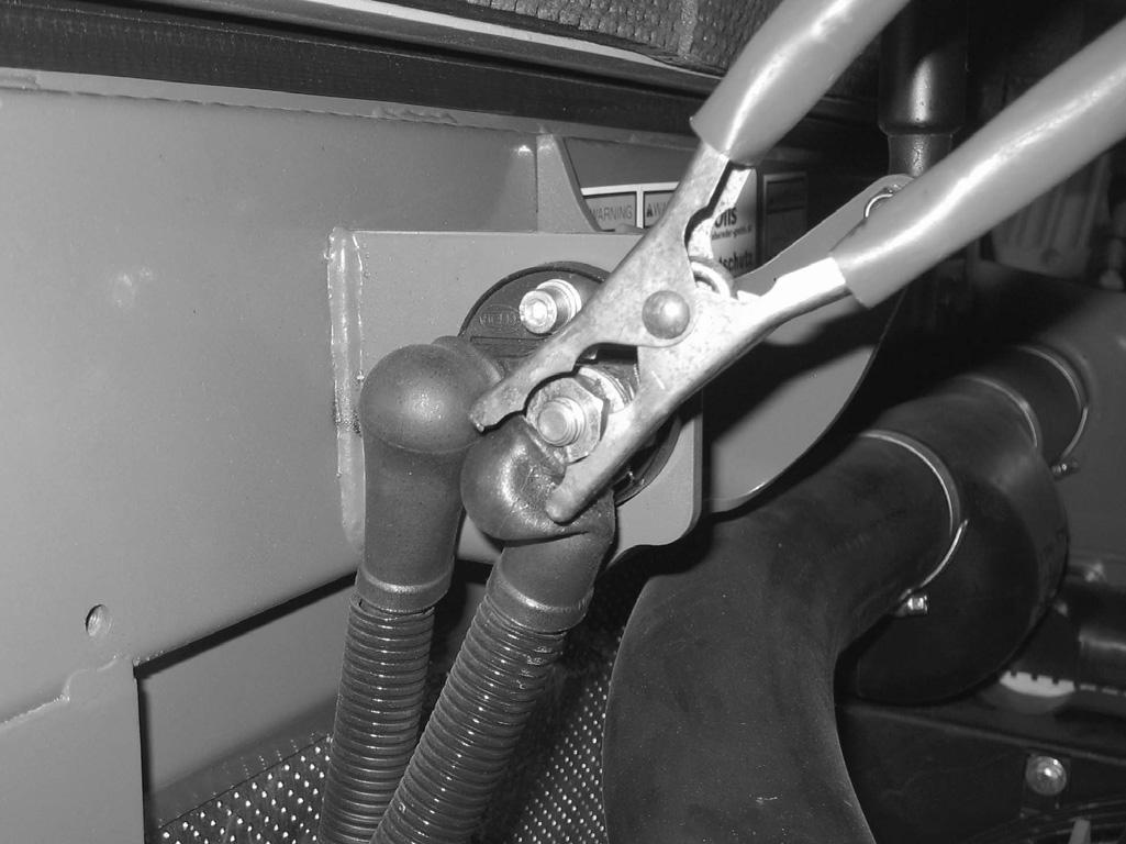
1.Position the machine on a level surface. On machines equipped with rubber tracks, position the excavator so the tracks are positioned with mark (1, Figure 4-22) on the top span of the track in between drive pinion (2) and track tension roller (3).

Warning
Do not loosen the grease fitting more than two turns, or the fitting could be ejected under pressure and cause injury. Keep your face and body away from the fitting when loosening.
6.Start the engine. Lower the unit to the ground.
7.Repeat this procedure for the other track.
2.Use the bucket and dozer blade to lift the unit up until a track is just clear of the ground as shown in Figure 4-23.
3.Shut off the engine. Remove the ignition key and take it with you. Lock out the controls by raising left control console.
4.Measure the clearance of the raised track at the second track roller from the drive gear. Deflection should be between 3/4-1” (20-25 mm).
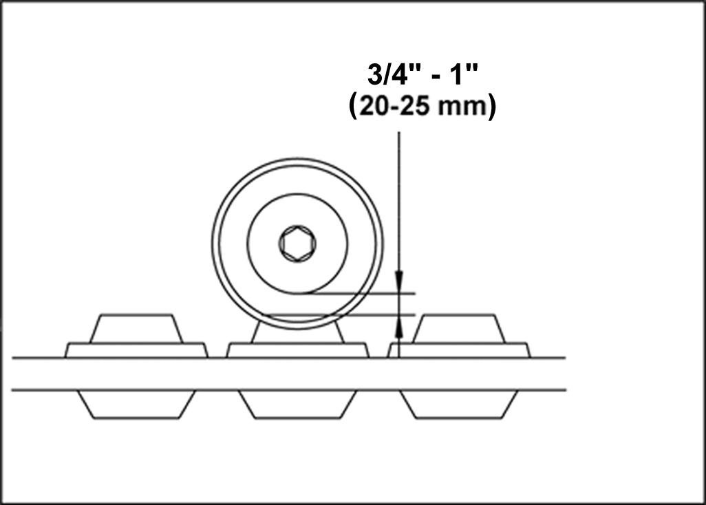
5.Using a grease gun, pump grease into the fitting until the track is properly tensioned (Figure 4-23).
Note: A grease gun is supplied with machine tool kit.
Important
Do not over-tension the track. If the track is too tight, loosen the grease fitting to relieve the pressure.
Windshield Washer Fluid
1.Shut off the engine. Remove the ignition key and take it with you. Lock out the controls by raising left control console.
2.Press the engine cover release button and raise the engine cover.
3.Open the windshield washer reservoir cover (1, Figure 4-24) and fill the tank with windshield washer fluid.
4.Close the windshield washer tank cover securely.
5.Close and latch the engine cover.
LONG-TERM STORAGE
If storing the machine for a long period (longer than two months), perform the procedures in this section.
Before Storage
1.Wash the entire machine.
2.Lubricate all grease zerks. See “Daily Lubrication” on page4-8.
3.Change the engine oil and filter according to “Changing Engine Oil and Filter ” on page4-11.
4.Add a fuel stabilizer to the fuel system according to the fuel supplier’s recommendations.
5.Remove and fully charge the battery. Store the battery in a cool, dry location.

6.If the machine will not be operated for a month or longer, apply grease to all exposed hydraulic cylinder rod areas or retract all cylinders so rod exposure is minimized. Apply grease to any remaining rod areas.
7.If the ambient temperature (at any time during the storage period) is expected to drop below freezing, make sure the engine coolant is either completely drained from the radiator and engine block or that the amount of anti-freeze in it is adequate to keep the coolant from freezing. Refer to the engine manual for anti-freeze recommendations and quantities.
8.Protect against extreme weather conditions such as moisture, sunlight and temperature.
During Storage
About once each month, connect the battery and check all fluid levels to make sure they are at the proper level before starting the engine.
Start the engine and allow it to run until it warms up and then move the machine a short distance to help relubricate the internal parts. Run the engine until the battery has a chance to recharge and then shut it off.
Important
If it is desired to operate the hydraulic cylinders at this time, BE SURE to wipe the protective grease (and any adhering dirt) from the cylinder rods prior to starting the engine. After operating, BE SURE to recoat the cylinder rods with grease if the machine is to be returned to storage.
After Storage
After removing the machine from storage and before operating it, perform the following:
1.Replace and re-connect the battery.
2.Wipe off grease (and any adhering dirt) from cylinder rods.
3.Check V-belt tension.
4.Check all fluid levels and top-off as necessary.
5.Start the engine. Observe all indicators. If all indicators are functioning properly and reading normally, move the machine outside.
6.When outside, park the machine and let the engine idle for at least five minutes.
7.Shut off the engine and walk around machine. Make a visual inspection looking for evidence of leaks.
8.Review and re-familiarize yourself with all safety precautions starting on page 4-1.
9.Follow the starting and warm-up procedures according to starting on page 3-16.
Engine
ProblemPossible CauseCorrective Action
Engine hard -starting or fails to start No fuelAdd fuel to tank; bleed air from fuel system
Incorrect engine oil SAE gradeReplace engine oil with proper grade; see "Fluid Capacities/Lubricants” on page1-4
Incorrect fuel gradeReplace fuel with proper grade; see "Fluid Capacities/Lubricants” on page1-4
Loose, or corroded starter circuit connectionsRepair starter circuit; contact authorized service center
Incorrect engine clearanceAdjust clearance; contact authorized service center
Battery power insufficientCharge battery or replace if necessary. See "Battery” on page4-16
Fuel filter contaminatedReplace fuel filter; see "Fuel Filter” on page414
Malfunctioning fuel injector(s)Repair fuel injector(s); contact authorized service center
Starter not working / pinion fails to engageRepair starter/pinion; contact authorized service center
Glow plug system not workingRepair glow plug system; contact authorized service center
Rough running engineIncorrect fuel gradeReplace fuel with proper grade; see "Fluid Capacities/Lubricants” on page1-4
Incorrect engine clearanceAdjust clearance; contact authorized service center
Fuel line leakageReplace fuel line; contact authorized service center
Malfunctioning fuel injector(s)Repair fuel injector(s); contact authorized service center.
Insufficient engine powerFuel line leakageReplace fuel line; contact authorized service center
Air filter contaminatedService air filter; see "Air Cleaner” on page412
Engine not at operating temperatureWarm up the engine
Incorrect fuel gradeReplace fuel with proper grade; see "Fluid Capacities/Lubricants” on page1-4
Incorrect engine clearanceAdjust clearance; contact authorized service center
Oil level too highAdjust oil level; see "Changing Engine Oil and Filter” on page4-11
Malfunctioning fuel injector(s)Repair fuel injector(s); contact authorized service center
Engine overheated.Check cooling system
Engine overheatsOil level too lowAdd engine oil; see "Checking Engine Oil Level” on page4-10
Fouled oil cooler finsClean oil cooler; contact authorized service center
Damaged fan. Damaged or loose V-beltReplace the fan / service V-belt; see "Checking and Adjusting V-belt Tension” on page423 or "Checking and Adjusting Air Conditioning V-belt Tension” on page4-24; contact authorized service center
Coolant level too lowAdd coolant; see "Checking Coolant Level” on page4-15
Oil level too highAdjust oil level; see "Changing Engine Oil and Filter” on page4-11
Oil level too lowAdd engine oil; see "Checking Engine Oil Level” on page4-10
Malfunctioning fuel injector(s)Repair fuel injector(s); contact authorized service center
High engine oil consumptionOil level too highAdjust oil level; see "Changing Engine Oil and Filter” on page4-11
Machine inclination too high15° maximum inclination up and across slopes; 25° maximum inclination down slopes
Incorrect engine oil SAE gradeReplace engine oil with proper grade; see "Fluid Capacities/Lubricants” on page1-4
Engine smokeBlueOil level too highAdjust oil level; see "Changing Engine Oil and Filter” on page4-11
Machine inclination too high15° maximum inclination up and across slopes; 25° maximum inclination down slopes
WhiteIncorrect fuel gradeReplace fuel with proper grade; see "Fluid Capacities/Lubricants” on page1-4
Engine starting temperature too low Wait for engine pre-heat cycle to complete before starting engine
Incorrect engine clearanceAdjust clearance; contact authorized service center
Malfunctioning fuel injector(s)Repair fuel injector(s); contact authorized service center
BlackAir filter contaminatedService air filter; see "Air Cleaner” on page412
Incorrect engine clearanceAdjust clearance; contact authorized service center
Malfunctioning fuel injector(s)Repair fuel injector(s); contact authorized service center
Indicator Lamps
ProblemPossible
Engine oil pressure indicator light comes on during operation
CauseCorrective Action
Engine oil pressure too lowStop engine immediately; check oil level and add oil if necessary; see "Checking Engine Oil Level” on page4-10; if oil level is correct, oil pump may have failed
Engine oil level too lowAdd oil; see "Checking Engine Oil Level” on page4-10
Oil pump not workingStop engine immediately; replace oil pump. Contact authorized service center
Machine inclination too high15° maximum inclination up and across slopes; 25° maximum inclination down slopes
Incorrect engine oil SAE gradeReplace engine oil with proper grade; see "Fluid Capacities/Lubricants” on page1-4
Water temperature display light comes on during operation (Engine overheating)
Coolant level too lowAdd coolant; see "Checking Coolant Level” on page4-15
Fan blades rotating too slowlyAdjust V-belt tension; see "Checking and Adjusting V-belt Tension” on page4-23 or "Checking and Adjusting Air Conditioning Vbelt Tension” on page4-24
Air filter contaminatedService air filter; see "Air Cleaner” on page412
Coolant system malfunctionService cooling system; contact authorized service center
Battery voltage light comes on during operation Alternator not charging properly / malfunctioning alternator Adjust V-belt tension; see "Checking and Adjusting V-belt Tension” on page4-23 or "Checking and Adjusting Air Conditioning Vbelt Tension” on page4-24; service alternator; contact authorized service center
Loose, or corroded charging circuit connections Repair charging circuit; contact authorized service center
Fuel light comes onLow fuelAdd fuel
Air filter light comes onAir filter contaminatedService air filter; see "Air Cleaner” on page412
Seals And Hoses
ProblemPossible CauseCorrective Action
Oil, coolant or fuel leakage under engine
Hydraulic fluid losses from hydraulic system
Loose hose connection(s)Tighten hose connection(s)
Seals or hoses damagedChange seals or hoses and check engine oil, engine coolant or fuel levels; add engine oil, coolant or fuel if necessary
Loose hose connection(s)Tighten hose connection(s)
Seals, hoses or lines damagedService seals, hoses and/or lines; contact authorized service center

