22 minute read
CHAPTER 3 – OPERATION


OPERATING CONTROLS Machine Orientation
Warning
•Read and understand this entire manual. Follow warnings and instructions for operation and maintenance. Failure to follow instructions can result in injury or death.
•Read and understand all safety decals before operating the machine. DO NOT operate the machine unless all factoryinstalled guards and shields are in place.
•Be sure you are familiar with all safety devices and controls before operating the machine.
•Know how to stop the machine before starting.
•Use only with approved accessories or referral attachments. The manufacturer cannot be responsible for safety if the unit is used with non-approved attachments.
•Check for correct function after adjustments or maintenance.
All references to “right” and “left” are determined from the operator's position facing forward.
Guards and Shields
Whenever possible, guards and shields are used to protect potentially hazardous areas on the machine. In many places, decals are also provided to warn of potential hazards or to display special operating procedures (see Chapter 2 – Safety).
The left operator’s console should be raised to enter and exit the cab. In the raised position, the console locks out all hydraulic functions of the machine. See Figure 3-1.
Pos. Description
28
Hydraulic oil filter indicator (red) – Hydraulic oil filter indicator light comes on when hydraulic oil filter requires servicingor while the hydraulic oil is cold.
29 Engine air filter indicator (red) – Air filter indicator light comes on when air filter requires servicing.
30
Battery charge fault indicator (red) – Battery charge indicator light comes on when the ignition is turned on and goes off when the engine starts. If the indicator light comes on while the engine is running, the battery is not charging, indicating a faulty charging circuit in the alternator or problems with the V-belt. NOTE: a faulty V-belt affects cooling pump operation, which can lead to overheating and more serious engine problems. Shut off the engine IMMEDIATELY and determine the cause if this indicator comes on when the engine is running.
31
Engine coolant temperature indicator (red) – Coolant temperature indicator light comes on if coolant temperature rises above specification.
32 Not assigned
33
Glow plug indicator (yellow) – Glow plug indicator light comes on when the ignition key is in the glow plug activation position. Indicator will go out when the glow plugs have heated sufficiently to start the engine.
34 Hourmeter – Indicates the total operating hours of the machine. Use the hourmeter to track maintenance in the maintenance log.
35
36
Fuel level gauge – The fuel level gauge shows the amount of fuel in the tank.
Engine oil pressure indicator (red) – Engine oil pressure light comes on when the ignition is turned on and goes off as soon as the engine is running. During normal operation, this indicator should remain off. The indicator will light if the engine oil pressure drops too low. If this occurs, shut off the engine IMMEDIATELY and determine the cause of the pressure drop.
37 Indicator light – Not assigned
38 Hydraulic oil temperature indicator light – Hydraulic oil temperature indicator light comes on when hydraulic oil is too hot.
39 High-speed switch (transport speed) – Pressing the switch will enable high travel speed.
40 Work light switch – Press switch to the ON position to turn on the boom work light.
41
Ventilation fan (two-speed) – Press the two-position switch to turn on the ventilation fan. Pressing switch to the first position is the low fan speed position, and the second position is the high fan speed position. If the heater control (cab model only) is in the heating position, this switch functions as the cab heater ON/OFF switch.
42 Air conditioning (option, cab only) – Press the switch to turn on the air conditioning.
43 Proportional control status indicator (option) – Indicates proportional control operation.
44 Windshield wiper switch (cab models only) – Pressing the two-position switch to the first position turns on the windshield wiper. Pressing and holding the switch indicator in the second position activates the washer fluid pump.
45 Roof lights (option) – Press switch to the ON position to turn on the roof light lights.
46 Rotating beacon (option) – Press switch to the ON position to turn on the boom work light. 47 Auto-idle switch (option) – Enables optional auto-idle feature. See page 3-11.
1.Fuel/water separator
2.Battery disconnect switch
3.Air cleaner
4.Fuel filter
5.Engine oil filter
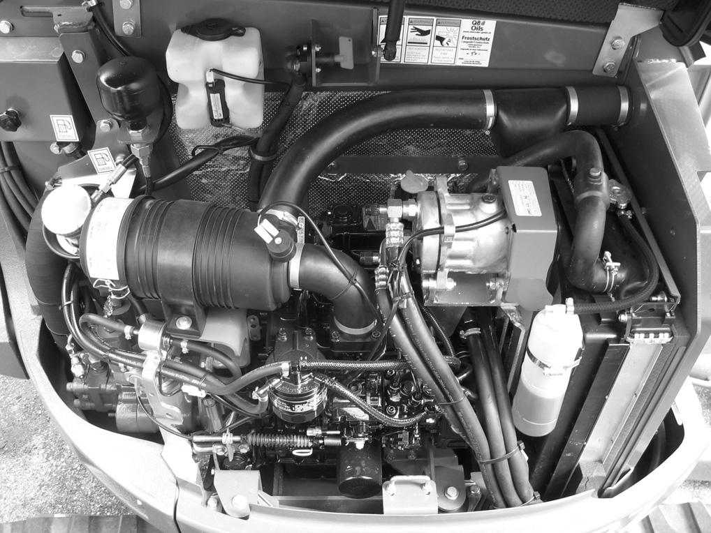
6.Engine oil dipstick
7.Engine oil fill (2 places)
8.Fuel filler cap

9.Hydraulic fluid filler cap
10.Hydraulic fluid level sight gauge
11.Radiator
12.Radiator overflow reservoir
13.Radiator cap

14.Windshield washer reservoir (cab only)
15.Hydraulic oil cooler

16.Battery (located under cab)

Ignition Key Switch
Note: The engine can only be started if the left control lever console is pivoted down into the operation position.

With the key in the fully counter-clockwise “P” position, all power is shut off. The key can be inserted or removed when the switch is in this position.
With the key in the “0” position, power to the accessory circuit is turned on. The key can be inserted or removed when the switch is in this position.

With the key in the “I” position, power is turned on to all controls and electrical circuits. The battery charge indicator light and the oil pressure indicator light will come on.
With the key in the “II” position, the glow plug indicator will come on while the glow plugs warm intake air in cold weather.
With the key turned fully clockwise “III” and held in position, the engine will crank/start. The indicator lights should go out when the engiine starts. Release the key after the engine starts (the key returns to the “I” position when it is released after starting the engine).
Note: The key must always be returned to the “I” position between attempts to start the engine in order to activate the glow plug system.
Battery Disconnect Switch
A battery disconnect switch is located in the engine compartment under the hood. The switch allows electrical lockout of all functions of the excavator. See Figure 3-6. To disconnect battery and lockout all electrical functions, turn key (1) of the battery disconnect switch counter-clockwise to position (2) and remove it. To reconnect battery and turn on all electrical functions, insert key (1) into the battery disconnect switch and turn clockwise to the notched position (3).
Travel Controls
Warning
•Levers and controls should return to neutral position when released.
•Be sure the levers and controls are in the neutral (middle) position before starting the engine.
•Operate controls gradually and smoothly. Excessive speed and quick control movements without regard for conditions and circumstances are hazardous and could cause an accident.
Warning
Be sure that the dozer blade is “in front.” When the operator’s cab is facing forward, the blade will be visible and travel controls will operate as expected. If the dozer blade is not visible, the operator’s cab is facing to the rear, and the travel controls will operate in reverse.
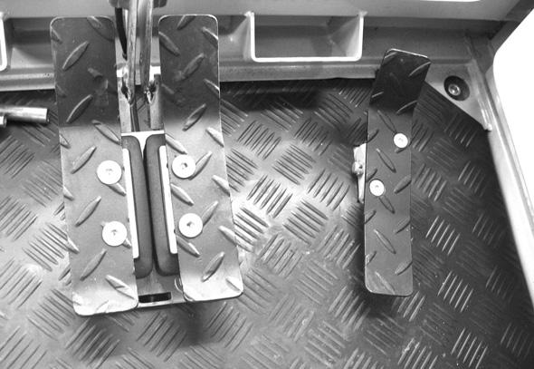
Forward Travel
Both travel control levers or pedals must be moved forward. The farther they are moved forward, the faster the machine will travel. See Figure 3-7.
Reverse Travel
Both travel control levers or pedals must be moved rearward. The farther they are moved rearward, the faster the machine will travel. See Figure 3-7.
Turning During Travel
Pivot (wide) turns are made by rotating only one track forward or rearward so the machine pivots on the stationary track. Spin turns are made by rotating one track forward and one track rearward. The machine will spin around its mid-point. See Figure 3-7.
Figure 3-7 Travel Controls
Spin Turn
Move the levers in opposite directions to spin the machine on its axis. To spin turn left, move the right control lever forward while pulling the left control lever to the rear; to spin turn right, move the left control lever forward while pulling the right control lever to the rear. See Figure 3-8.

SAE/ISO Selector
See page 3-11.
SAE Operating Controls
SAE boom and bucket functions are controlled by the right and left joystick control levers located on the seat consoles.
SAE Left Joystick – See Figure 3-9.

1 – Arm extend
2 – Arm retract
3 – Swing left
4 – Swing right
ISO Operating Controls
ISO boom and bucket functions are controlled by the right and left joystick control levers located on the seat consoles.
ISO Left Joystick – See Figure 3-11.


1 – Boom lower
2 – Boom raise
3 – Swing left
4 – Swing right
5 – Boom lower
6 – Boom raise
7 – Curl bucket in
8 – Curl bucket out
ISO Right Joystick – See
5 – Arm extend
6 – Arm retract
7 – Curl bucket in 8 – Curl bucket out
Note: The joystick controls are pilot-operated. The farther the controls are moved from center, the faster the machine will function.
Note: The joystick controls are pilot-operated. The farther the controls are moved from center, the faster the machine will function.
Tilting the Cab or Canopy
Warning
•Always tighten cab lock-down nuts before driving or using the machine.
•Always close the cab door before tilting the cab.
•Stay clear from underneath the cab as it is tilted.
•Always secure the tilt rod in the support position when the cab is tilted.

Refer to items 1-11 in Figure 3-13 to safely complete the following procedure.
Tilting the cab or canopy up:
1.Follow “Mandatory Safety Shutdown Procedure” on page 2-2.
2.Raise the floor mat (1) on the right, front of the cab and remove cab lock-down nut (2). Remove cab lock-down bolt (3) at the right rear of the cab.

3.Securely close the cab door.

4.Locate the jack handle tubes (4) from the tool kit in the engine compartment, insert them into the jack (5) and extend the jack as far as it will go. The cab will be raised as far as the jack (5) will travel.
5.Pull on handle (7) until the cab is completely tilted and supported by the safety cable (8).
6.Remove the tilt support (9) from the storage bracket (10) and slide the tilt support into the guide bracket (11) and secure with the retention pin.
Tilting the cab or canopy down:
1.Remove the tilt support (9) from the guide bracket (11) by removing the retention pin and slide the tilt support out of the guide bracket. Secure the tilt support into the storage bracket (10). Replace the retention pin back into the guide bracket for storage.
2.Use handle (7) to slowly lower the cab back onto the jack.
3.Remove jack handle tubes (4) from the jack and insert the opposite end of the jack handle tubes onto the release pin (6). Slowly twist the release pin counter-clockwise until the cab is lowered.
4.Turn the release pin (6) clockwise.
5.Reinstall the cab lock-down nuts (2) and (3).

6.Place the jack handle tubes (4) back in the tool kit.
Caution
Check the tilt support (9), retention pin (11) and safety cable (8) at regular intervals for cracks and cuts. Replace defective parts immediately.
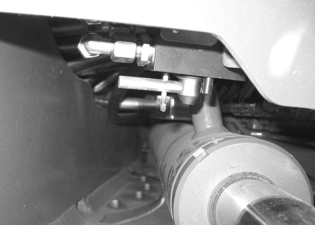
SAE/ISO Operating Controls Selector
Note: See page 3-9 for SAE/ISO joystick operation.
The SAE/ISO selector is located inside the front of the chassis at the top of the swing cylinder opening. See (1), Figure 3-14. The machine has been set at the factory for SAE standard operation shown in the top photograph. If ISO operation is desired, loosen wing nut (2) and rotate to the position in the bottom photograph and retighten wing nut (2).
Throttle Lever
The engine speed is controlled by the throttle lever (1) located behind the left joystick. See Figure 3-15.
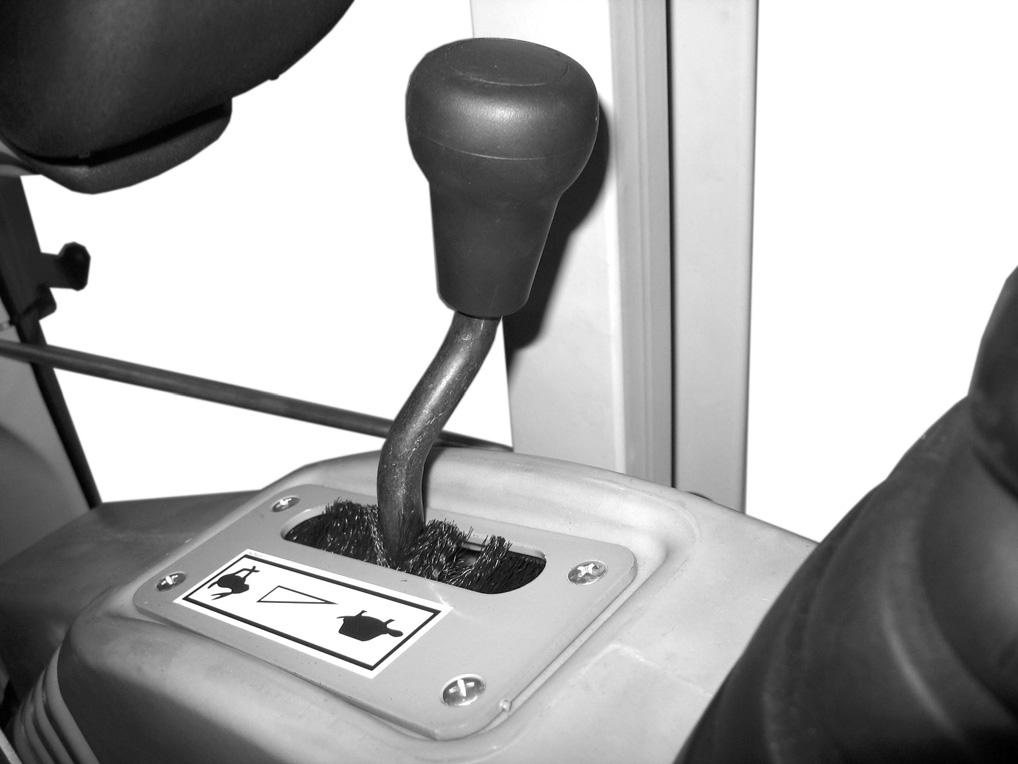

•Push throttle lever (1) forward to decrease engine speed.
•Pull throttle lever (1) rearward to increase engine speed.
Optional Auto-Idle Feature
Serial Numbers AG00573 and Up
Press switch (1) to enable the auto-idle feature. When the auto-idle feature is enabled, engine speed is automatically lowered to idle when no hydraulic functions occur for five seconds. Engine speed resumes when a hydraulic function is activated.
Boom Swivel Pedal
The boom can be swiveled without moving the swing frame by pressing and holding the auxiliary hydraulic/ changeover button (1, Figure 3-17) on top of the left hand joystick, and then pressing the boom swivel pedal (2) forward or rearward. Pressing and holding the auxiliary hydraulic/changeover button (1) and pressing the front of the auxiliary hydraulics pedal (2) swivels the boom to the left. Pressing and holding the auxiliary hydraulic/changeover button (1) and pressing the back of the auxiliary hydraulics pedal (2) swivels the boom to the right.

When the auxiliary hydraulic/changeover button is pressed and boom swivel is enabled, indicator (3) is lit.

Dozer Blade
The dozer blade is controlled by the dozer control lever (1) located next to the right joystick. See Figure 3-18.
•Push lever forward to lower the blade.
•Pull lever rearward to raise the blade.

Operator’s Seat Adjustments
Note: The operator’s seat left console must be raised in order to exit the cab. In the lowered or work position, all operational functions are activated, and operator exit is blocked by the warning arm/lever. In the raised position, the all hydraulic functions of the machine are locked out.
3.Armrest Adjustments
Angle Adjustment
Use the armrest angle adjustment spindle (1, Figure 3-20) to change the angle of the armrest.
Height Adjustment
Use the armrest height adjustment (2) to raise/ lower the armrest as a unit.
Note: The rear of the left armrest has a turnbuckle that may need to be adjusted to allow the left armrest to rotate out of the way when the left console is raised. Use the turnbuckle to adjust the armrest so it does not contact the left control lever when raising the left console to the lock-out position.
3-19 Seat Adjustment – Cab Shown
1.Seat Suspension Adjustment
Rotate the knob / lever (1) to adjust the seat suspension for the operator’s weight. An indicator on the front of the seat base shows the weight adjustment in kilograms. (1 kg = 2.2 lbs.) Adjust the seat suspension correctly to ensure a comfortable ride. See Figure 3-19.

2.Horizontal Seat and Control Adjustment
The seat adjustment lever (2) allows the operator to move both the seat and the controls forward and rearward.
Figure 3-20 Armrest Adjustments

4.Backrest Adjustment
The backrest adjustment lever (4) allows the operator to move the backrest forward and rearward.
5.Headrest Adjustment
The headrest adjustment (5) allows the operator to move the headrest up and down.

6.Seat Height Adjustment
The seat height adjustment allows the operator to move the seat height up and down. To raise the seat height, grasp the seat and lift up until you hear an audible click. To lower the seat, raise the seat to the highest position and then lower the seat to its lowest position.
Seat Belt
Warning
ALWAYS fasten the seat belt securely and properly. Never operate the machine without the seat belt fastened around the operator.
Keep the seat belt clean because dirt can impair seat belt operation. Check seat belt condition regularly and have damaged or worn belts immediately repaired by an authorized workshop.
After an accident the seat belt strap is stretched and must be replaced with a new strap installed by an authorized workshop.
Make sure the seat belt is not twisted when it is fastened, and that it is fastened over the hips and not the stomach.
Fasten the seat belt tightly and securely. Remove hard, edged or fragile objects from your pockets or clothes that might lie between the seatbelt and your body.
Fastening/Unfastening the Seat Belt
Fasten the seat belt around your hips and waist and insert tab (A, Figure 3-21) into buckle (B) until it clicks securely in place. Slack in the seat belt should automatically retract into seat belt spool (D).
Unfasten the seat belt by pressing button (C).
Ventilation – Cab Only Windshield

Warning
When opening the windshield, be sure to lock both latches. When closing the windshield, keep hands on the handles and away from the path of the window.
Opening the Windshield
The windshield can be opened for ventilation. Squeeze/ turn the latches (1, Figure 3-22) located at the upper corners of the windshield. Grasp the handles (2) and pull the windshield up until the latches lock in the open position.


Caution
Support the windshield when releasing it from the ceiling catches to avoid possible head injury.
To close the windshield, re-install the lower windshield (if removed), and squeeze/turn the latches, and then lower the windshield and lock the latches in the closed position.
Cab Door Latch Release
When fully opened, the left cab door will latch in position to the side of the cab. To release the latch, use the knob (1) located on the inside of the door frame. See Figure 3-23.
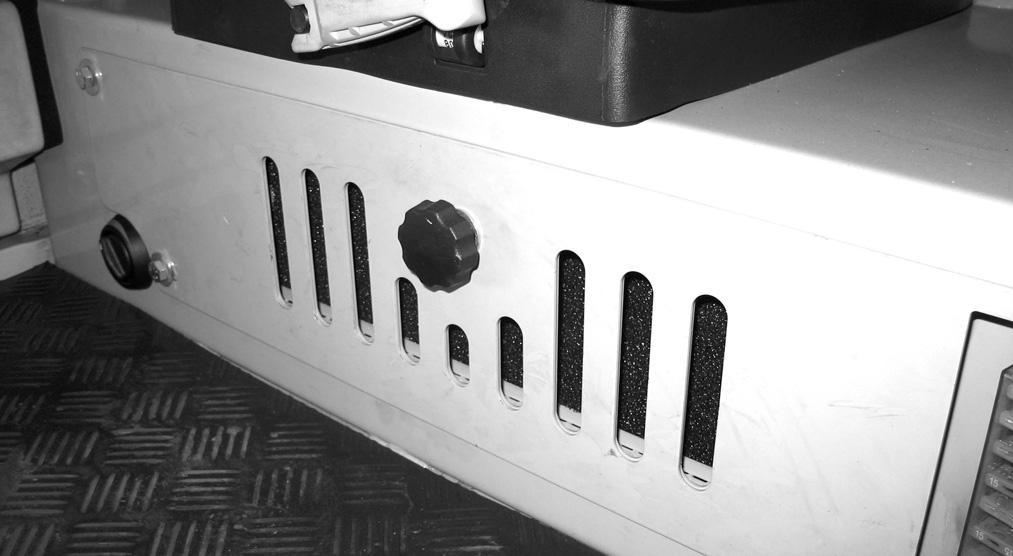


Cab Heat Control (cab only)
During the colder months, the operator’s cab heater can be operated using the heater control (1, Figure 3-25) on the right of the kick plate below the operator’s seat. Rotate the control clockwise to reduce the heat; counter-clockwise to increase the heat.
Recirculated Air Mode (cab only)
When heating or cooling the cab, the recirculated air mode heats or cools using only air from inside the cab and not air from outside the cab. Sliding the plate to the left will turn OFF the recirculated air mode by closing the vent (Figure 3-25). Sliding the plate to the right will turn ON the recirculated air mode by opening the vent.
Interior Light
The interior light is located on the back of the cab above the rear window. Press the switch to the right or left to turn the light ON. Move the switch to the center position to turn the light OFF.
Tool Kit and Cab Jack Handle
The machine tool kit and the cab jack handle are located in the storage area under the hood in the engine compartment.
Machine Operation
Warning
•Read and understand this entire manual. Follow warnings and instructions for operation and maintenance. Failure to follow instructions can result in injury or death.
•Read and understand all safety decals before operating the machine. DO NOT operate the machine unless all factory installed guards and shields are in place.
•Be sure you are familiar with all safety devices and controls before operating the machine.
•Know how to stop the machine before starting.
•Use only with approved accessories or referral attachments. Manitou Americas, Inc. cannot be responsible for safety if the unit is used with nonapproved attachments.
•Check for correct function after adjustments or maintenance.
Pre-Operation Checklist
Important
See the table of recommended lubricants in “Fluid Capacities/Lubricants” on page1-4 for the proper engine and hydraulic oil specifications. Only use lubricants specified in the table.
Check the following items at the beginning of each work day or every 12 working hours:
•Seat belt and mounting hardware
•Safety decals (replace as required)
•Air cleaner and intake hoses
•Engine coolant level and system for leaks
•Clean engine area of any flammable materials
•Engine oil level (Fill if required)
•Water drained from fuel pre-filter
•Hydraulic system for leaks
•Hydraulic fluid level (Fill if required)
•Pivot points lubricated and operating properly
•Track tension
•Windshield washer reservoir level (if cab installed)
•Broken and/or loose parts (Repair as required)
•Left armrest down in operating position
•Attachment safely locked on machine
•Engine cover closed
•Fuel level
Important
Do not completely drain the fuel tank while running the excavator. If this happens, air will enter the fuel system, and the fuel system will have to be bled. Always completely fill the tank with fuel at the end of the working day.
Warning
Never use ether starting aids. Glow plugs are used for cold weather starting. The glow plug can cause ether or other starting fluid to detonate, causing injury.
Engine Start and Stop
Note: When all machine controls are stationary (no pilot control pressure), the swing motor and travel motor brakes are automatically applied. When any control is activated, the appropriate brake is automatically released.
Note: All hydraulic functions are locked out when the operator’s seat left console is in the raised position.
Engine Start Procedure
Danger
DO NOT run the engine in an enclosed area without proper ventilation. Be sure there is adequate fresh air if running the machine in an enclosed area.
1.Adjust the operator’s seat to desired settings.
2.Fasten the seat belt.
3.Be sure all levers and controls are in the neutral positions.
4.Make sure no one is dangerously close to the machine.
5.Insert the ignition key into the switch and turn it clockwise to the (II) position. Indicators for oil pressure and battery voltage will light. In cold weather, the glow plug indicator will come on while the glow plugs warm the engine.
6.Turn the key fully clockwise and hold it until the engine starts, and then release the key.
Note: The key must be returned to the (I) position between attempts to start the engine in order to activate the glow plug system.
Important
Do not activate the starter motor for longer than 20 seconds during each starting attempt. If the engine does not start, turn the key fully counter-clockwise, wait 30 seconds, and then attempt to start the engine again.
Important
Indicator lights must go out when engine starts. If they do not, turn the engine off IMMEDIATELY. Do not use the machine until the problem has been identified and repaired.
7.Allow engine to warm up at idle speed for approximately 10 - 15 minutes to fully warm up all systems.
8.Test the controls.
Cold-weather Engine Starting Procedure
Note: Install an in-block or tank-style engine heater, which will keep engine block and oil warm for easier cold-weather starting.
Note: Be sure the engine oil is correct type and viscosity for the ambient (air) temperature. Refer to “Fluid Capacities/Lubricants” on page1-4.
Note: Be sure the battery is fully charged.
1.Start the engine according to “Engine Start Procedure” on page3-17
2.Advance the throttle to 1/4 engine speed for a faster warm up.
3.As the engine warms up, move the throttle lever to the idle position.
After Starting/During Operation
Check the following after startup and during operation. Stop the engine and fix problems before continuing operation.
1.Warning indicator lights on?
2.Travel drive/steering operating properly?
3.Boom, dipper, cab rotation and bucket controls operating properly?
4.Engine exhaust excessively smoky?
Engine Shut-down
Mandatory Safety Shutdown Procedure
Before leaving the machine:
1.Bring the machine to a complete stop on a level surface. Avoid parking on an incline or a hillside, but if this is not possible, park across the slope.
2.Lower the working equipment to the ground and support it securely.
3.Run the engine at idle speed for a few minutes to allow systems to cool after operation at full speed.
4.Turn the key fully counter-clockwise to shut off the engine. Wait for all movement to stop.
5.Move the joysticks in all directions to verify the hydraulic system is de-pressurized.
6.Lock out controls by raising left control console.

7.Remove the ignition key and take it with you. Exit the machine using the hand-holds.
New Machine Break-in Procedure
A new machine requires reduced operational speed during the first 100 operating hours for proper break-in. If the machine is subjected to hard use during the break-in period, damage to the machine may occur.
Perform the following when operating a new machine:
•Perform all steps in “Pre-Operation Checklist” on page3-16.
•Start engine and let it idle for 10 - 15 minutes so all components and systems can warm up.
•Operate the machine at about 80% of maximum loads and speed.
•At the end of the first 100 operational hours, drain and replace the engine oil and engine oil filter.
Travel
Warning
•Before operating the travel levers, be sure that you know in which direction the machine is pointing. If the dozer blade is not visible from the operator’s cab, you are looking at the rear of the machine and the travel controls will be the reverse of normal operation.
•Before moving, be sure that there are no personnel in the way of the machine. Sound the horn to alert workers that you are about to move the machine.
•Be sure the path is clear during travel.
•Use extreme caution when reversing travel. Be sure there is a clear path behind the machine.
•Operate the travel control levers smoothly to avoid sudden starts and stops.
Travel Speed Selection
Two travel speed ranges can be selected by using the travel speed switch (1) located on the control console. See Figure 3-26. The machine uses an “Auto2Speed” transmission on the drive motors. This feature enables the transmission to automatically switch from highspeed to low-speed when it senses a load.
Travel speeds are:
•Slow-Speed Maximum = 1.7 mph (2.8 km/h)
•High-Speed Maximum = 2.9 mph (4.7 km/h)
Caution
The slow-speed setting should be selected to prevent automatic up-shifts if conditions warrant.
General Travel Instructions
1.Avoid sudden movements and sharp turns.
2.Travel slowly on rough, frozen, or uneven terrain.
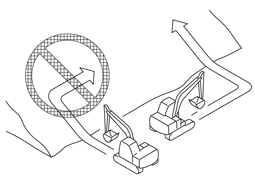
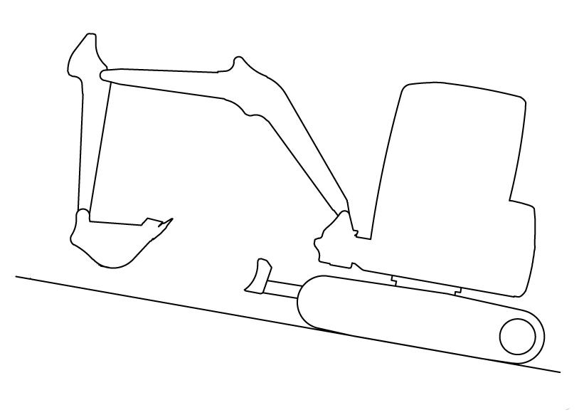
3.Travel straight up and down slopes — never across. See Figure 3-27. Extend arm and lower boom to keep the bucket about 12” (300 mm) off the ground. If the machine starts to slide or becomes unstable, lower the bucket to regain control. If the engine stalls, lower the bucket, make sure that all controls are in the neutral position and restart the engine. See “Operating on Slopes” on page3-22 for more information about operating the machine on slopes.
Traveling on Slopes
Warning
•Do not travel up a slope steeper than 15°. Do not travel down a slope steeper than 25°. Keep the boom centered while traveling.
•Keep attachments as low as possible when traveling on slopes and or rough terrain.
Traveling on a slope is hazardous. When traveling, use the following guidelines:
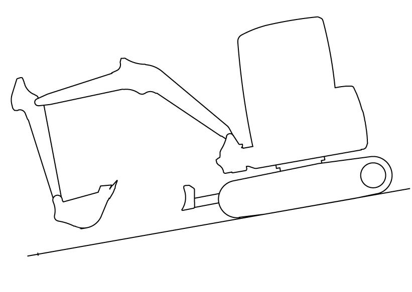
•Travel straight up and down slopes—never across. See Figure 3-28.
•See Figure 3-28 on where to place the dipper arm, boom and bucket for uphill and downhill travel. Raise the bucket 10” – 12" (20 cm – 30 cm) off the ground for better stability. If the machine starts to slide or becomes unstable, lower the bucket to regain control. If the engine stalls, lower the bucket, be sure that all controls are in the neutral position and restart the engine.

Figure 3-27 Travel Down Slope
4.To travel straight, push both travel control levers (or pedals) forward (or rearward). The farther the levers (or pedals) are moved, the faster the travel speed.
5.Pivot (or wide) turns are made by rotating only one track forward (or rearward). The machine will pivot on the stationary track.
6.Spin turns are made by rotating one track forward and one track rear. The machine will spin around its center.
7.The excavator can travel in water as deep as the top of the upper track rollers. Be sure that the footing is solid so the machine will not sink.
•When traveling down a slope, control the speed with the travel levers and the throttle control; reduce engine speed.
•To achieve the best stability while excavating, lower the dozer blade to the ground.
•Avoid traveling over objects such as rocks, trees, stumps, etc.
•Stop the machine travel before moving the bucket or dozer blade controls.
Operating Instructions
Joystick Controls
Extending and retracting the cylinders (boom, arm and bucket) are controlled by the joysticks located on the consoles attached to the operator’s seat. See “Equipment and Controls” on page3-2 for control configurations.
Note: The joystick controls are pilot-operated. The farther the controls are moved from center, the faster the machine will function.
Hydraulic Swivel Unit Brake
The upper carriage’s rotation is sufficiently braked by moving the control lever back to the initial position. Moving the control lever in the opposite direction brakes the upper carriage with full hydraulic pressure.
Important
Hydraulic swivel unit brake function is not optimal if the hydraulic system has not reached operating temperature.
Mechanical Stop Brake
A multi-disc brake integrated into the rotation drive has an additional mechanical brake effect with a time delay. This brake is used to stop the swivel unit from rotating in any position.
Operating Precautions
Danger
•DO NOT push down with the dozer blade to elevate the front end of the tracks. This will cause the machine to become unstable.
•DO NOT excavate underneath the machine.
•Always be sure that there is adequate support when working near trenches or drop-offs. Be aware of conditions that could cause the trench/drop-off wall to collapse, resulting in risk of injury or death.
•Do not position the machine directly underneath structures during demolition. Falling objects or structure collapse could cause severe damage or personal injury.
•Be sure that there is the proper clearance from overhead electrical lines.
•Be sure that all underground electrical power and gas supply lines are clearly marked and avoided.
Warning
•DO NOT rest your feet on the travel pedals during normal machine operation. Unexpected machine movement could occur in this situation.
•When working close to an excavated edge, be sure that the ground the machine is sitting on is solid. Keep the travel motors to the rear. See Figure 3-29.
DO NOT use machine travel or swing to provide additional breakout force when the bucket is in the ground.
DO NOT jam the bucket into the ground and use the weight of the machine to provide additional breakout force.
When working on soft or muddy ground, be sure that the machine is not sinking.
DO NOT use the bucket as a hammer or ramming device.
Important
When digging at maximum excavation depth, BE SURE that the dozer blade does not contact the boom cylinder. Damage to the boom cylinder may occur if it contacts the dozer blade.
Operating on Slopes
Warning
•Do not travel up or across a slope steeper than 15°. Do not travel down a slope steeper than 25°. Keep the boom centered while traveling.
•Keep attachments as low as possible when traveling on slopes or rough terrain.
Operating on a slope is hazardous. It is recommended the work area be leveled as shown in Figure 3-30. If this is not possible, use the following guidelines:
3-30 Level Work Area on Slope
•Travel straight up and down slopes — never across. See Figure 3-27. Extend arm and lower boom to keep the bucket about 12” (300 mm) off the ground. If the machine starts to slide or becomes unstable, lower the bucket to regain control. If the engine stalls, lower the bucket, be sure that all controls are in the neutral position and restart the engine.


•When traveling down a slope, control the speed with the travel levers and the throttle control.
•When traveling down grades that exceed 15°, put the machine in the position shown in Figure 3-31. Reduce engine speed.
Operating in Water
Do not operate or immerse the machine in water higher than the top of the upper track rollers.
Thoroughly grease the machine if it has been operated in deep water.
Operating Auxiliary Hydraulics
Use the auxiliary hydraulics pedal (1, Figure 3-32) to regulate oil flow through auxiliary attachments. Press the pedal forward (F) for oil to flow into the auxiliary attachments and rearward (R) for oil to flow out.
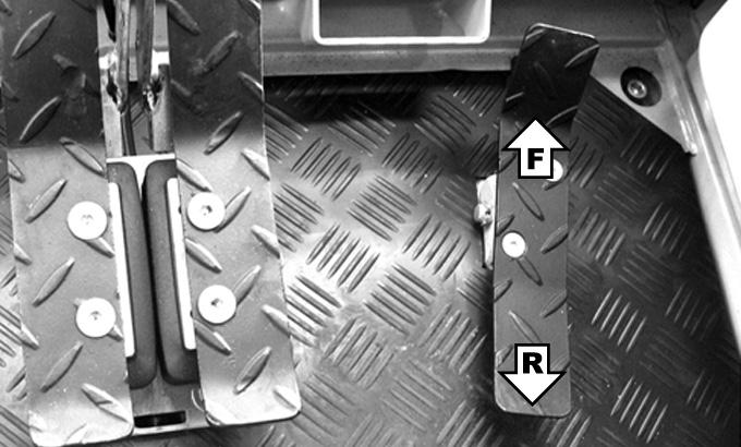

Figure 3-31 Travel Down Slopes
•To achieve the best stability while excavating, lower the dozer blade to the ground.
•Operate as slowly as possible and avoid sudden changes in direction.
•Avoid traveling over objects such as rocks, trees, stumps, etc.
•Stop the machine travel before moving the bucket or dozer controls.
•Slow the work cycle. Take your time.
•Avoid working with the tracks positioned across the slope. Position the machine with the blade downhill and lowered.
•Avoid swinging or extending the bucket farther than necessary in a downhill direction. If you must swing the bucket downhill, keep the boom low and skid the bucket along the ground.
•When working with the bucket on the uphill side, keep the bucket as close to the ground as possible. Unload far enough away from the excavation to prevent the possibility of a cave-in.
Operating in Cold Weather
In cold weather, mud should be removed from the machine before parking. If possible, park the machine on solid ground, or wood planks, to prevent the track or undercarriage from freezing to the ground.