7 minute read
PREPARING FOR FIELD OPERATION


TRACTOR & DRAWBAR REQUIREMENTS (Fig. 24)
The tractor, to be used to operate a Disc Conditioner, MUST have:
1.A minimum of 65 hp for the DC2340 and 75 hp for the DC2360
2.A 540 RPM or 1000 RPM PTO
3.PTO and hitch dimensions conforming to the ASAE Standard S 203 (see Figure 24)
4.Two remote hydraulic outputs capable of powering a double-acting cylinder
Adjust the tractor drawbar to meet the ASAE Standard drawbar dimensions shown. The recommended distances are 18″ (457mm), from the ground to the top of the drawbar, and 8″ (200mm), from the top of the drawbar to the centerline of the PTO shaft. The distance from the tractor PTO to the center of the hitch pin should be 14″ (355mm) on 540 RPM tractors and 16″ (406mm) on 1000 RPM tractors, to avoid damage to the front Telescoping PTO Drive Shaft.
NOTE: To prevent damage to the Disc Conditioner Telescoping Drive and PTO Tower, avoid making sharp left hand turns while unit is operating.
The tractor should be equipped with a safety cab.
ATTACHMENT TO TRACTOR (Figs. 27, 26 & 28)
Quick Attach Drawbar Extension (Units after Serial Numbers
DC2340–6100 &
DC2360–8150)
The Quick Attach Hitch Extension can be adjusted to fit tractor drawbars 1–1/8 to 1–3/4″ (29 to 44 mm) thick and 2 to 3–7/16″ (51 to 88 mm) wide. Spacers of 1–1/4″ , 1–3/8″,1–1/2″ and 1–5/8″ are also provided to reduce the hitch pin hole. The Hitch Extension MUST be adjusted fit the tractor drawbar before use and MUST be readjusted when connecting to a tractor with a different size drawbar. Unless otherwise directed, refer to Fig. 25 for the following steps:
1.Set the tractor drawbar to specifications shown in Fig. 24.
2.Select the largest Spacer that fits inside the tractor drawbar hitch pin hole.
NOTE: The Spacer is stored on the Drawbar Extension Hitch Pin when the Drawbar Extension is removed from the tractor.
3.Unlock and pull out the Hitch Pin.
4.Remove and retain the 1/2″ Cap Screw and Lock Washer.
5.Adjust the 3/4″ Cap Screws to clear the tractor drawbar.
1 – 14″ (356mm) for 540 RPM Units 16″ (406mm) for 1000 RPM Units
2 – 6″ to 12″ (152mm to 305mm)
3 – 16″ to 20″ (406mm to 508mm)
4 – 22″ (559mm) for 540 RPM Units 24″ (610mm) for 1000 RPM Units
5 – PTO MUST be Level With or Slightly Inclined To the Tractor PTO Shaft
Fig. 24
6.With the Hitch Extension placed loosely on the tractor drawbar, determine the maximum amount of Shims that can be placed in the Hitch Box. Remove the Hitch Extension from the tractor drawbar. Align the Shims with the Hitch Pin and secure with the retained 1/2″ Cap Screw and Lock Washer.
7.Install the Quick Attach Hitch Extension Assembly by placing the Spacer inside the tractor drawbar hitch pin hole, sliding the Assembly on the tractor drawbar. Secure by inserting the Hitch Pin through the Hitch Box, the Spacer and tractor drawbar, and lock with the Hitch Pin Lock provided.
8.Adjust all 3/4″ Cap Screws against the tractor drawbar to center the Hitch Box on the drawbar within 1/16″ (1 mm). Tighten the 3/4″ Jam Nuts on one side. Loosen the two Cap Screws on the opposite side just enough (less than 1/12 turn) to allow the Hitch to slide on the tractor drawbar, then tighten the two Jam Nuts.
9.Store extra Shims, Spacers and Instruction Card in the plastic Box provided. Proceed to theConditioner Tongue Hitch Plate installation topic.
Drawbar Extension (Units before Serial Numbers DC2340–6101 & DC2360–8151)
1.Set tractor drawbar to specifications shown in Fig. 24.
2.Referring to Fig. 26, install Drawbar Extension Assembly to tractor drawbar. Tighten 5/8″ Bolts to 100 foot-pounds (136 Nm) torque and 1″ Nut to 480 foot-pounds (650 Nm) torque.
1 – Disc Conditioner Drawbar (Tongue)
2 – Hitch Plate
3 – Hitch Pin Lock
4 – Hitch Pin
5 – Drawbar Extension
6 – 1″ Slotted Hex Nut & Lock Washer
7 – 3/16 x 2″ Cotter Pin
8 – 5/32 x 1-3/4″ Cotter Pin
9 – 5/8″ Slotted Hex Nut & Lock Washer
10 – Tractor Drawbar
11 – 5/8″ Flat Washer (3). Use as Required
12 – 5/8 x 4″ Cap Screw
13 – 1 x 4″ Cap Screw
14 – 1″ Flat Washer (3). Use as Required
15 – 5/8 x 2–1/2“ Cap Screw (4)
16 – 5/8“ Hex Nut (4)
17 – 5/8“ Lock Washer (4)
18 – 3/16 x 1–3/4“ Cotter Pin
Fig. 26
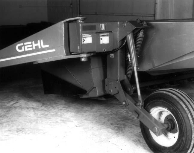
Conditioner Tongue Hitch Plate
NOTE: If the tractor is equipped with a 3-point hitch, raise the lower arms to their maximum height (or remove them) to avoid interference with the Telescoping Drive and PTO Tower on the Disc Conditioner.
The Drawbar Extension and Hitch Plate MUST be bolted to the tractor drawbar and end of the Disc Conditioner Drawbar (Tongue) in such a manner as to make the front Telescoping Drive Shaft as level as possible, when Header is resting on the ground. MAKE SURE to follow the measurement information as shown in Figure 24. One of the many possible Hitch Plate and Drawbar attachment positions is illustrated in Figure 26.
1.Raise Disc Conditioner tongue to clear the Hitch Pin and back tractor to align Hitch Pin with hole in Hitch Ball on Tongue. Lower Tongue to rest on Hitch Pin. Install Hitch Pin Lock in Hitch Pin to secure.
After the connection is made, remove the Hitchjack and secure it to the “Storage Hub” on the top of the Tongue.
NOTE: If the available mounting positions do NOT permit the Driveline to be level, position the Drive to be slightly inclined to the tractor PTO shaft. Do NOT position the Driveline to run slightly down to the tractor PTO shaft.
PTO
Clean and lightly grease the splines on the tractor PTO shaft and the Yoke of the Telescoping Drive. Depress the Safety Lock Ring and slide the Yoke onto the tractor PTO shaft. Move the Yoke back and forth until the
Warning
BE SURE that the PTO Safety Lock Ring is positively engaged and that the Tongue is securely connected to the tractor drawbar Hitch Extension with a Locking Clip Pin, BEFORE starting the tractor engine. Also, BE SURE that the tractor PTO shield is in place and properly secured and that the Telescoping Drive Shields are rotating freely BEFORE starting the tractor engine.
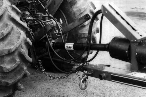
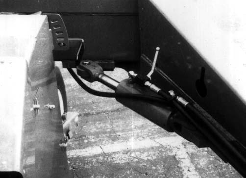
HYDRAULIC TONGUE CONTROL (Fig. 29)
The Hydraulic Swing Tongue Positioner uses a 3″ bore Hydraulic Cylinder (provided) to control the Tongue movement. The Hydraulic Tongue Positioner enables moving the Tongue to any position, from transport to full cutting width, while remaining on the tractor seat. This is extremely useful for steering the unit around obstacles, for finishing narrow strips without running down windrows and, for cutting square corners.
Warning
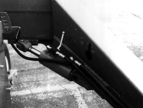
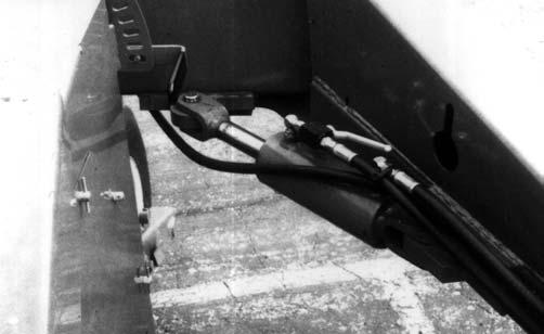
HYDRAULIC LIFT (Fig. 29)
NOTE: The tractor MUST have a remote hydraulic output capable of handling a double-acting cylinder.
Install the appropriate quick-disconnect fitting (to match your tractor connection) onto the Lift Cylinder Hose using Loctite or equivalent pipe sealing compound. Make the Lift Cylinder Hose attachment to the tractor, start the tractor and operate the valve to raise and lower the Disc Conditioner several times to purge the air out of the system.
NOTE: If the Disc Conditioner is NOT horizontal, when it is being raised and lowered, refer to the Service chapter for corrective measures.
Do NOT remove Hydraulic Tongue Control Cylinder with Conditioner Header off the ground. Failure to heed can result in death or serious injury.
NOTE: Operation of the Tongue Control Cylinder requires a tractor with two remote hydraulic outputs; one for the Tongue Control and another for the Lift Control.
Adjust the Cutting Height and Header Flotation following information in the Adjustments chapter of this Manual.
NOTE: Whenever the Conditioner is operated on a tractor other than the original tractor the Conditioner was set up for, the Drawbar Height and Header Flotation must be checked and adjusted accordingly.
SAFETY CHAIN (Fig. 28)
Only a Safety Chain (NOT an elastic or nylon/plastic tow strap) should be used to retain the connection between the towing and towed machines, in the event of separation of the primary attaching system. Refer to Optional Features & Accessories chapter for part number information.
BREAK-IN
Before starting to cut and condition, it is recommended that the Disc Conditioner be broken-in by running it empty for approximately 20 minutes. This initial run-in should be done with the Header on the ground and the Tongue in the cutting position. Before running the unit however, perform the daily (10 hour) maintenance routines listed in the beginning of the Operation chapter. The Break-in should consist of a five minute and a fifteen minute running period. First, run the unit for five minutes with the tractor engine close to idle RPM. Next, stop the unit and exercise the MANDATORY SAFETY SHUTDOWN PROCEDURE (page 8) before leaving the tractor seat to reinspect the unit. After inspection is complete, reconnect the PTO, restart the tractor, engage the PTO near engine idle speed and gradually increase the speed to proper operating RPM and continue running the machine for 15 minutes. After another inspection, the Disc Conditioner is ready for the field.
NOTE: The oil in the Cutterbar and the Gearbox MUST be changed after the first 10 hours of operation. For details, see the Lubrication chapter of this Manual.
Transporting
BEFORE transporting the Disc Conditioner, refer to the Transporting chapter of this manual for additional transporting information.
Chapter 11 Transporting
Transport Locks
(Figs. 30, 31 & 32)
When either model Disc Mower Conditioner is going to be transported on a public highway, BE SURE to raise the unit all the way up and activate both Lift system Transport Locks. Also, BE SURE to swing the Drawbar to the Transport position with the Hydraulic Hitch Positioner and position the Transport Lock Valve on the Cylinder in the Transport (“closed”) position.
SMV
& REFLECTORS (Fig. 30)
Both Disc Mower Conditioner models are provided with a Slow-moving Vehicle Emblem Mounting Bracket on the upper left back end of the Conditioner Frame. A Slow-moving Vehicle Emblem, if required by local laws and regulations, is supplied by the customer. Red Reflector Strips are also provided at the rear corners of the Conditioner Frame.
SAFETY
LIGHTING (Fig.
Caution
ALWAYS follow state and local regulations, regarding a safety chain (NOT an elastic or nylon/plastic tow strap) and auxiliary lighting, when towing farm equipment on public highways! A safety chain should always be used, to retain the connection between the towing and towed machine, in the event of separation of the primary attaching system. BE SURE to check with local law enforcement agencies for your own particular regulations. NEVER transport the Disc Mower Conditioner at speeds greater than 20 mph.
As required or when desired, Disc Mower Conditioner can be equipped with a safety chain for operation on public highways. A sturdy Chain Loop is welded to the side of the Drawbar to facilitate anchoring the Chain. The safety chain, when attached in this manner, has the following characteristics:
1.Chain is sufficiently slack to allow turns and movements of either the tractor or the farm implement, without placing tension on Chain.
2.Chain is of sufficient strength to hold the decoupled implement (and its load) and tow it to the shoulder.
A GEHL Safety Chain, part number 803098, is available through your GEHL Dealer.