26 minute read
CHAPTER 5 CONTROLS & SAFETY EQUIPMENT


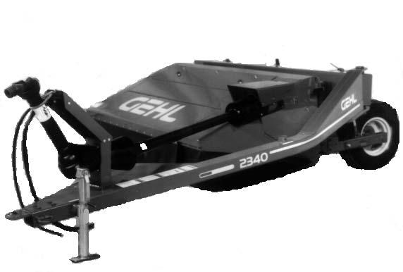
The Disc Mower Conditioner is provided with several features for operator safety and convenience.
Caution
Become familiar with and know how to use ALL Safety Devices and Controls on the Disc Mower Conditioner, BEFORE attempting to operate this equipment. Know how to STOP Disc Mower Conditioner operation BEFORE starting it.
Drawbar Hitch Positioning Caution
BEFORE transporting the Mower Conditioner on a public highway, BE SURE to install and lock the Positioner Cylinder, in the retracted “Transport” position, with the Transport Lock Valve provided.
Repositioning the Disc Mower Conditioner Drawbar (Tongue), between the “Transport” and operating positions, can be accomplished hydraulically.
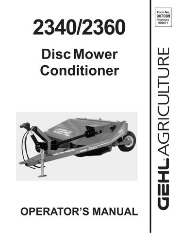
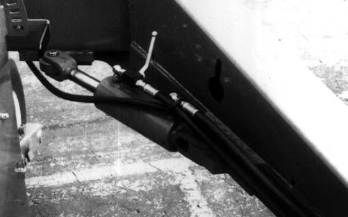
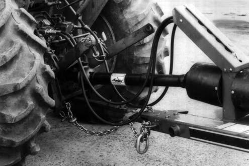
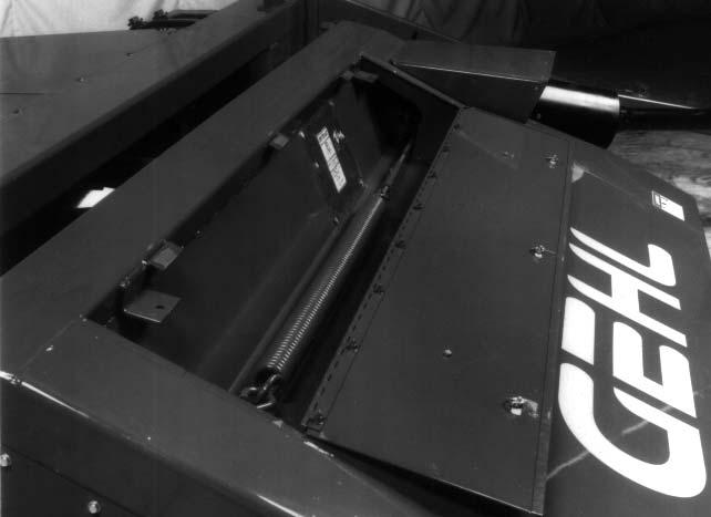
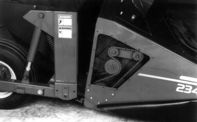
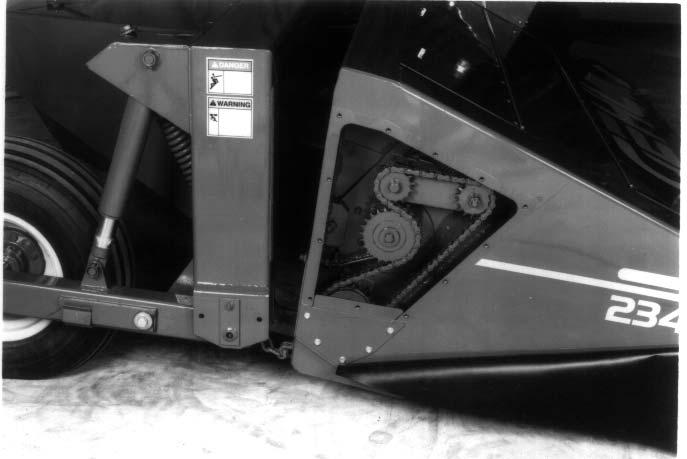
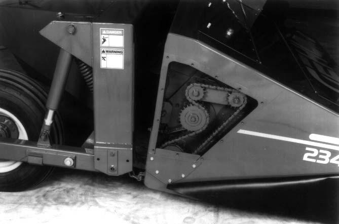
Hydraulic Hitch Positioner (Fig. 1 & 2)
The Disc Mower Conditioner is equipped with a Hydraulic Hitch Positioner for remotely (from the tractor seat) relocating the Drawbar from the “Transport” to the field operation positions. The Hydraulic Hitch Positioner contains a double-acting hydraulic Cylinder, Hoses and a Transport Lock Valve. When the Disc Mower Conditioner is in use in the field, the Transport Lock Valve should be in the “open” position. When the Disc Mower Conditioner is in the transport position, the Transport Lock Valve MUST be in the “closed” position. Keep Transport Lock Valve in the “closed” position only during unit transport.
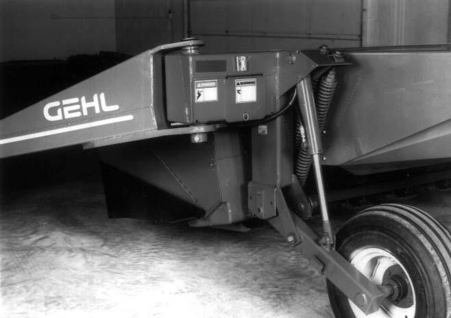
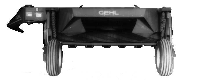
GUARDS & SHIELDS (Fig. 3)
Whenever and wherever possible and without affecting machine operation, Guards and Shields have been used, on this equipment, to protect potentially hazardous areas. In many places, Decals are also provided to warn of potential dangers as well as to display special operating procedures.
Warning
Read and observe ALL Warnings on the unit, BEFORE operating it. Do NOT attempt to operate this equipment unless ALL factory installed Guards and Shields are properly secured in place.
Implement Drive Line Shields
The Front Telescoping PTO Drive, between the PTO Tower and tractor PTO shaft, and the Rear Telescoping PTO Drive, between the PTO Tower and Gearbox, are equipped with rotating Shields.
Warning
BE SURE that the Rotating Shields on the Telescoping Drives turn freely BEFORE starting the tractor engine.
Caution
BEFORE proceeding to perform any work on the Disc Mower Conditioner and, BEFORE removing any Guards and opening any Covers and Shields, BE SURE to exercise the MANDATORY SAFETY SHUTDOWN PROCEDURE (page 8). Also, BE SURE to replace ALL Guards, Shields and Covers BEFORE operating the unit.
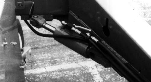
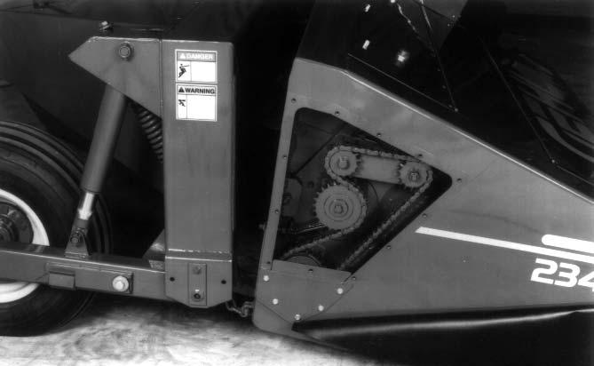
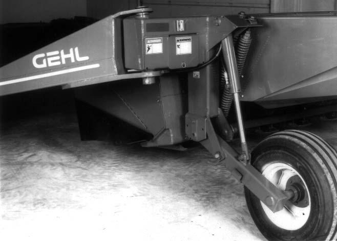
HEADER LIFT SYSTEM (Fig. 4)
Both Disc Mower Conditioner models use a remotely controlled (from the tractor seat) single-acting hydraulic Cylinder “master-slave’’ system, to raise and lower the Header. Before transporting the unit, BE SURE to raise the unit as high as possible and activate the Transport Lock on both sides of the unit.
Miscellaneous Guards
Various latched and hinged Guards, Shields, Curtains and Covers are provided on both model Disc Mower Conditioners to enable access for lubrication, service and adjustment. MAKE SURE any damaged or worn Guard, Shield, Curtain or Cover is replaced BEFORE attempting to operate the Disc Mower Conditioner.
Caution
BEFORE transporting the Disc Mower Conditioner, raise the unit as high as possible and engage both Transport Locks.
HITCHJACK (See Fig. 3)
A Hitchjack is furnished with the Disc Mower Conditioner to support the machine when the tractor is disconnected as well as to facilitate aligning the Hitch Clevis with the tractor drawbar for hookup. When the Jack is NOT being used to support the Disc Mower Conditioner, it can be removed and relocated to a “storage” position on top of the Drawbar.
Warning
BE SURE the Locking Pin is properly seated into the holes through the Jack Tube and the “Supporting Position” Hub on the Drawbar, BEFORE disconnecting the Mower Conditioner from the tractor.
SAFETY CHAIN (Fig. 5)
Caution
ALWAYS follow state and local regulations regarding a safety chain (NOT an elastic or nylon/plastic tow strap) and auxiliary lighting when towing farm equipment on public highways! A safety chain should always be used to retain the connection between the towing and towed machine, in the event of separation of the primary attaching system. BE SURE to check with local law enforcement agencies for your own particular regulations.
As required or when desired, the Disc Mower Conditioner should be equipped with a safety chain and auxiliary lighting for transporting the unit on public highways. A sturdy Chain Loop is welded to the side of the Drawbar to facilitate anchoring the chain. Refer to the Optional Features & Accessories chapter for ordering information.
TELESCOPING DRIVE COUPLER (Fig. 3)
The Front Telescoping Drive is equipped with Springloaded Locking Devices to positively lock it onto the tractor PTO shaft and the Rear Drive Shaft mounted in the Drawbar Tower. Depress the Locking Device against the Spring tension and slide the Yoke onto the tractor PTO shaft. Release the Locking Device and move the Yoke ahead or back until the Lock engages into the groove of the PTO shaft. The same process is used to install the other end of the front Telescoping Drive Line to the Shaft mounts in the Drawbar Tower. MAKE SURE the phasing notch on the PTO is properly oriented with the Tower Shaft. When towing the Disc Mower Conditioner behind a vehicle that does not have a PTO drive shaft to secure the Front Drive Line to, the Drive Line Must be removed from the Disc Mower Conditioner. DO NOT move Disc Mower Conditioner with the Front Drive Line setting on Drive Line Storage Prop.
Warning
BE SURE that the Telescoping PTO Coupler is properly secured to the tractor PTO shaft and unit Tower Shaft BEFORE starting the tractor engine.
TRANSPORT LOCKS (Figs. 1, 2 & 4)
When either model Disc Mower Conditioner is going to be transported on a public highway, BE SURE to raise the unit all the way up and engage both Right and Left Header Lift System Transport Locks. BE SURE to also swing the Drawbar to the Transport position and place the Transport Lock Valve in “closed” Position.
NOTE: DO NOT operate the PTO when the Disc Mower Conditioner’s Drawbar (Tongue) is in the Transport Position. This position puts an excessive load angle on the Rear Drive Joint. This excessive load angle will cause premature component wear.
Chapter 6 Operation Caution
BEFORE starting the tractor engine and running the Disc Mower Conditioner for the first time, review and comply with ALL SAFETY recommendations set forth in the SAFETY chapter of this manual.
Emergency Shutdown
In an emergency or in case a foreign object enters the Header area, STOP cutting material IMMEDIATELY by disengaging the tractor PTO. Then, exercise the MANDATORY SAFETY SHUTDOWN PROCEDURE (page 8) BEFORE leaving the tractor seat to remedy the problem.
START-UP CAUTION
BE SURE ALL factory installed Guards and Shields are properly secured in place BEFORE starting the tractor engine. Be certain that NO people are within 50 feet of the unit when engaging the PTO.
To avoid unnecessary strain on the Disc Mower Conditioner Drive Line components, ALWAYS engage the tractor PTO slowly with the tractor engine at less than half throttle. Bring the unit to PTO speed BEFORE starting to cut. Always operate at PTO speed! Attempting to operate at higher than PTO speed could cause excessive vibration, wear and early component failure. In addition, operating the unit at slower than PTO speed will cause poor windrow formation and increase the chances of plugging.
Starting The Field
NOTE: BEFORE proceeding to cut, raise and lower the Header a couple of times to insure that it is operating properly.
After the field has been checked and is known to be free of obstructions, it can be opened by cutting the first swath in a counterclockwise direction. However, it is recommended to make two or three clockwise rounds first to expose any potential hazards around the edge of the field. Then, proceed to cut and condition the backswaths by operating in a counter-clockwise direction around the field. The field can then be divided into sections, as desired.
Ground Speed
The Disc Mower Conditioner can be operated in a wide range of ground speeds depending on crop conditions and/or terrain. Any change in ground speed should be made by changing tractor gears and NOT by increasing or decreasing tractor engine RPM.
Unplugging
It is possible for the Disc Mower Conditioner to plug in two different areas. It can become plugged in the Disc area slipping the Drive Line Clutch, or the unit can become plugged in the Conditioning Rolls causing Bandbelt to slip.
Plugged Discs
To clear a plugging condition in the area of the Discs:
1.Shut off the PTO.
2.Raise the Header all the way up.
3.Exercise the MANDATORY SAFETY SHUTDOWN PROCEDURE (page 8) and lock the tractor parking brake.
4.Engage both Header Transport Locks.
5.Carefully clear the plug from the Cutterbar area.
6.If the plugging occurs frequently, refer to the Troubleshooting chapter for additional directives.
Plugged Conditioning Rolls
To clear plugging from the Conditioning Rolls, proceed as follows:
NOTE: If either the Conditioner Drive Belt or Slip Clutch starts to slip, stop forward travel and disengage the PTO IMMEDIATELY!
1.Stop forward movement of the tractor and disengage the PTO.
2.Raise the unit up fully.
3.Exercise the MANDATORY SAFETY SHUTDOWN PROCEDURE (page 8) and lock the tractor parking brake.
4.Engage both Header Transport Locks.
5.Open Front Cover on Header and remove excess material. Turn Cutterbar Disc in a reverse direction to back out the plug from between the Rollers.
6.If the plugging occurs frequently, refer to Troubleshooting chapter for additional information.
Hilly Conditions
Under hilly conditions, it is necessary to add a 95% calcium chloride solution to the left tire for additional stability.
Chapter 7 Adjustments Caution
BEFORE proceeding to perform any adjustments on this unit, exercise the MANDATORY SAFETY SHUTDOWN PROCEDURE (page 8).
The DC2340 and DC2360 Disc Mower Conditioners have been designed and factory adjusted to function properly under most field operating conditions. However, due to the wide range of operating conditions encountered, some additional readjustments may be required.
Caution
BEFORE proceeding to adjust the cutting height, exercise the MANDATORY SAFETY SHUTDOWN PROCEDURE (page 8).
HEADER FLOTATION (Figs. 6 & 7)
NOTE: BE SURE to place the Header in the operating position before proceeding to adjust the flotation. In addition, when operating the Disc Mower Conditioner with a high PTO horsepower tractor, the flotation may have to be set heavier on the left side of the Header to counteract the higher rotational torque’s tendency to lift the Header off the ground.
The Header flotation is adjusted by varying the setting of the Flotation Springs on each end of the Header. Lower the Header to the operating position, loosen the Jam Nuts and tighten or loosen the Spring Bolts to achieve the desired flotation. For normal conditions, the flotation should be set with enough force to just lift each end of the Header off the ground. In rocky or rough conditions, the flotation should be set lighter to protect the Cutterbar. At higher mowing speeds, heavier settings follow terrain better.
NOTE: Any change of cutting height or Drawbar height will change the Header flotation. BE SURE to readjust the flotation, if necessary, to avoid damaging the Cutterbar Knives. Also, when making a flotation adjustment to the left side of the Header, BE SURE to adjust both Springs evenly, to avoid damaging the U-bolt Anchor on the bottom end of the Springs.
CUTTING HEIGHT (Fig. 8)
The cutting height can be adjusted from 1-1/2″ (38mm) to 4″ (102mm) using the Disc Angle Adjustment.
NOTE: Any change to the cutting height requires that the flotation be checked and readjusted, as necessary.
DISC ANGLE (Fig. 8)
The Disc angle is infinitely adjustable from 3° down (4″ , 102mm cutting height) to 10° down (1-1/2″, 38mm cutting height). In rocky or rough conditions, use a flatter or 3° Disc angle to protect the Disc Blades. In down, tangled and lodged crops, use a steeper or 10° Disc angle to obtain a clean cut.
Caution
Raise the Header, exercise the MANDATORY SAFETY SHUTDOWN PROCEDURE (page 8) and install the Transport Locks BEFORE proceeding to adjust the Disc angle.
To change the Disc angle, it is necessary to move the rear pivot of the third Link forward (10°) or backward (3°). To adjust the Disc angle, loosen the Crossbolt and use the Adjustment Nuts to make the desired change.
NOTE: A Disc angle change will change the Header flotation. To avoid damage to the Discs or Blades, BE SURE to readjust the Header flotation after changing the Disc angle.
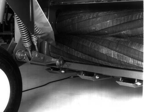
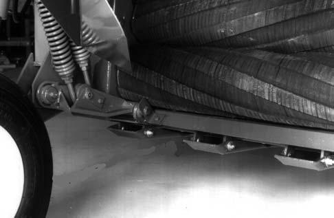
SKID SHOES (Fig. 9)
The Skid Shoes are located on the underside of the Cutterbar Frame and are NOT adjustable.
CONDITIONER ROLL PRESSURE (See Fig. 10)
The Conditioner Roll pressure determines the amount of conditioning done to the crop (assuming the Roll gap is properly adjusted) and should be used accordingly. For crops like alfalfa and clover (legumes), use only enough Roll pressure to crack and kink the stems. If the leaves show dark spots and/or the tops of the plants are being clipped off, too much Roll pressure is being used. In grass-type crops, more Roll pressure is required than for legume-type crops.
NOTE: If the Conditioner Rolls are separated too far, there is NO amount of Roll pressure that will do a satisfactory job, in most crop conditions.
Adjust Conditioner Roll Pressure Spring by adjusting the threaded Turnbuckle and Rod system. Spring pressure is normally adjusted from the factory at 48″ (1220mm) overall Spring length including hooks. Move Turnbuckle Ends together to increase Roll pressure. DO NOT overtighten! Prevent Spring Rods from rotating as Turnbuckle is tightened. Lubricate threads to ease adjustment.
Once Spring pressure is set, change amount of crop conditioning by varying Roll spacing. Greater Roll spacing results in less crop conditioning while less Roll spacing results in greater crop conditioning.
NOTE: Do NOT reduce the Roll pressure to the point where there is NO Spring force on the Rolls. Damage can occur to the Roll Pressure Chain, if the Roll pressure is too low, allowing the Rolls to open and close freely.
Conditioner Roll Gap
(See Fig. 11)
The Conditioner Roll gap is the distance between the top of the lug on one Roll and the root of the lug of the mating Roll. The Roll gap should be set from 1/16 to 1/8″ (1.6 to 3.2mm), for most crops. However, it may be desirable to increase the Roll gap, when cutting thick-stemmed cane-type crops.
NOTE: Always check the Roll gap at several points along the entire length of the Rolls and at every 90° of rotation. The gap must always be maintained at a minimum of 1/16″ (1.6mm). Operating at closer than this minimum gap or with Rolls touching will result in damage to the Conditioner Rolls, Bearings and Frame.
The Conditioner Roll gap can be changed by adjusting the Stop Bolt at each end of the Header. First loosen the Locking Jam Nut. Turning the Stop Bolt into the Header will open the Rolls increasing the gap. Turning the Stop Bolt out will close the Rolls decreasing the gap. BE SURE to retighten the Locking Jam Nuts after the desired gap has been set.
NOTE: If the Conditioner Rolls are separated too far, there is NO amount of Roll pressure that will do a satisfactory job of conditioning, in most crops.
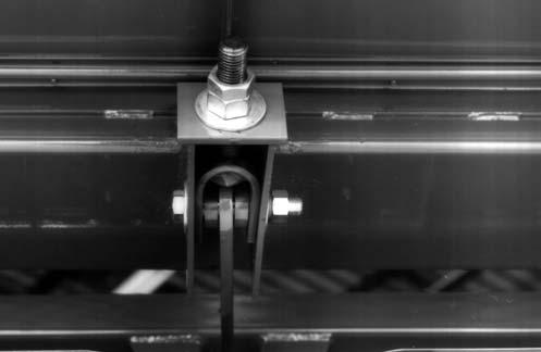
TOP ROLL CHAIN DRIVE TENSION (Fig. 11)
The Roll Drive Chain is tensioned by a Spring on the Roll Chain Idler. This Spring tension is NOT adjustable.
NOTE: When the Spring no longer puts tension on the Idler, replace the Roll Drive Chain.
WINDROW TO SWATH ADJUSTMENT (See Fig. 12)
The Disc Mower Conditioner will make anything from a narrow windrow to a wide swath, by moving the adjustable Deflector up or down. Raise the Deflector for a narrow windrow and lower the Deflector for a wide swath. The Deflector can be adjusted using the Deflector Adjustment Handle. The maximum swath width achievable is 72″ (1830mm) for the DC2340 or 86″ (2185mm) for the DC2360. Fine tune windrow width setting by adjusting Forming Chamber Sides. Narrow windrow width is 2-1/2′ (813mm).
CONDITIONER ROLL DRIVE BELT TENSION (Fig. 12)
The Compression Spring, on the Belt Idler, should be set at a 3-5/8″ (92mm) overall length.
Chapter 8 Lubrication
General Information Caution
NEVER attempt to lubricate the machine when any part of the unit is in motion. ALWAYS, BE SURE to exercise the MANDATORY SAFETY SHUTDOWN PROCEDURE (page 8), BEFORE proceeding to lubricate the machine.
It is well to remember that a sufficient amount of oil or grease will prevent excessive part wear and early failure.
Cutterbar
NOTE: The oil in the Cutterbar MUST be changed after the first 10 hours of operation.
It is difficult to accurately check the oil in the Cutterbar. If in doubt as to the amount of oil contained in Cutterbar, do NOT add oil. Drain and refill the Cutterbar. The oil should be changed every 200 hours or at least annually (more often if operated under heavy loads). The Cutterbar MUST be drained completely so that the exact volume of oil required can be put back into the Cutterbar. The following procedure MUST be followed:
1.Operate the Disc Conditioner for 10 minutes so that the Cutterbar reaches operating temperature.
2.Raise the Disc Conditioner to the transport position and engage the Transport Locks.
3.Park the Disc Conditioner so that the left rear corner of the Cutterbar is the lowest point on the Cutterbar.
4.Exercise the MANDATORY SAFETY SHUTDOWN PROCEDURE (page 8).
5.Remove the Skid Shoe from the left end of the Cutterbar. Remove the Overflow Plug from the bottom of the Cutterbar and the Filler Plug located between the second and third Disc on top of the Cutterbar. Allow the oil to drain completely. Wait for the dripping to stop.
6.Reinstall the Overflow Plug and the Skid Shoe. Refill the Cutterbar with SAE 80 GL 4 oil (DC2340, 7 Disc Cutterbar, 4 pt, 1.9 L) (DC2360, 8 Disc Cutterbar, 4–1/2 pt, 2.13 L).
NOTE: In some areas SAE 80 GL 4 oil may not be available. A GL 4 or GL 5 grade SAE #80W90EP Gear Lube is an acceptable substitute. The Cutterbar should be checked daily for oil drips and dust accumulation around the Seals. Oil drips or dust accumulation indicate that the Seals are leaking. Oil which is tan in color and foams excessively indicates that it has water present.
NOTE: There will be signs of oil at the Overflow Plug. A small amount of oil in this location should be considered normal.
GEARBOX (CHECK DAILY)
A Dipstick is provided for checking the oil level in the Gearbox. The correct oil level range is between the bottom line and top line on the Dipstick when the Cutterbar angle is less than 5° or cutting height 3 to 4″ (76 to 102mm). For cutting angles of from 5° to 10°, the correct oil level range is between the bottom line and NOT MORE than 3/4″ (19mm) above the top line on the Dipstick. The oil should be changed every 200 hours of operation or annually (more often if operated under heavy loads). The gearbox holds 4.8 qts (4.5 L) of SAE #80W90EP Gear Lube.
The Gearbox should be checked occasionally for oil drips and dust accumulation around the Seals. Oil drips or dust accumulation indicate that the Seals are leaking. Oil which is tan in color and foams excessively indicates that it has water present.
NOTE: The oil in the Gearbox MUST be changed after the first 10 hours of operation.
OILING (CHECK DAILY)(See Fig. 13)
NOTE: When checking Roller Chain Oil Bath oil level, MAKE SURE to remove all debris from the water drain holes in the Conditioner Roll Spring compartment.
The Roller Chains are enclosed and oiled in a sealed Oil Bath on the right side of the Disc Conditioner. The oil should be changed every 100 hours of operation or bi-annually (more often if operated under heavy loads). The Oil Bath holds 3 qts (2.84 L) of SAE #80W90EP Gear Lube. Check oil level as shown in Figure 13. The Oil Bath should be checked occasionally for oil drips and dust accumulation around the Seals. Oil drips or dust accumulation indicate that the Seals are leaking. Oil which is tan in color and foams excessively indicates that it has water present. To change the oil, observe the following steps:
1.Remove the Top Right Cover.
2.Remove Lower Right Cover to allow oil to drain.
3.With a rag, wipe out the lower areas of the Frame.
4.Clean and apply silicone sealer to the Lower Cover. Clean Cover mating surface of Frame and install Lower Cover.
5.Refill Oil Bath with 3 qts (2.84 L) of SAE #80W90EP Gear Lube.
6.Clean and apply silicone sealer to the top area of Lower Cover where Top Cover seats. Clean Top Cover and mating surface of Frame and install Top Cover.
Apply a good grade of foaming aerosol lubricant, such as NAPA Chain and Cable Lubricant, to the Front and Rear Telescoping PTO Drive Shields.
Sealed Bearings
Sealed Bearings are used throughout the machine to provide trouble-free operation, with a minimum of maintenance and lubrication. These Sealed Bearings are lubricated for life and relubrication is NOT required, NOR should it be attempted.
Greasing
NOTE: Grease all fittings on a prescribed basis, at the intervals of operation listed, before and after storing the unit and as otherwise listed. Use a good grade of lithium base grease.
Wipe dirt from the fittings before greasing to prevent any dirt from being forced into the Bearings or pivots. Replace any missing fittings, when noted. To minimize dirt build-up, avoid excessive greasing.
NOTE: In addition to the fittings, inspect and repack the Wheel Bearings at least once a season. The Telescoping PTO Drives should also be separated and grease applied to the splines at least three times during the harvesting season.
Grease Fitting Locations
Grease Every 10 hours (or Daily)
1.Telescoping PTO Drive Crosses (4 Places)
2.Telescoping PTO Drive Tube (2 Places)
3.Overrunning Clutch (1 Place)
4.Third Link (2 Places)
5.Inner Left Pusharm (3 Places)
6.Inner Right Pusharm (2 Places)
7.Right and Left Wheel Leg Pivots (2 Places)
8.Nylon Bushings on Non-rotating Driveline Shields (export models, Non-rotating Driveline Shield PTOs ONLY)
Chapter 9 Service
General Information Caution
BEFORE proceeding to perform all Service routines on this unit, exercise the MANDATORY SAFETY SHUTDOWN PROCEDURE (page 8).
NOTE: The following information is also referred to in the Troubleshooting chapter of this manual. It should be understood that all services, detailed in this chapter, are Owner-Operator responsibilities. Where indicated, certain service routines should only be carried out by (or under the direction of) an authorized GEHL equipment dealer.
SEALED BALL BEARING REPLACEMENT (Fig. 14)
Sealed Ball Bearings are used on various Shafts, around the unit. This type of Bearing is generally retained, in place, with a Self-locking Eccentric Collar. The Lock Collar has a counter bored recess, which is eccentric with the Collar bore. This eccentric recess engages or mates with an eccentric end of the Bearing inner ring, when the Bearing is assembled on the Shaft. The Bearing is engaged, on the inner ring cam, by the Collar. This assembly grips the Shaft tightly with a positive binding action that increases with use. The Collar Set Screw provides supplementary locking.
A Bearing can be removed from the Shaft by loosening the Set Screw and tapping on a punch which is placed in the drift pin hole, to loosen the Collar. Install Bearings with self-locking Collars in the following manner:
1.Place the Bearing and Collar on the Shaft with the cam surfaces next to each other. Tighten the bolts on the Bearing Retainers.
2.Mate the cam, of the Lock Collar, with the cam, of the Bearing inner ring.
3.Press the Locking Collar against the Bearing wide inner ring and turn it, in the direction of Shaft rotation, until it tightly engages. Tighten the Collar further by tapping on a punch inserted in the drift pin hole.
NOTE: Avoid damaging the Collar by over-tightening it.
4.Last, tighten the Set Screw in the Locking Collar.
Conditioner
Conditioner Roll Timing
(Figs. 15, 16 & 17)
The Conditioner Rolls are properly timed when the lug of one Roll is centered in the groove of the mating Roll. BE SURE the Roll Drive Chain is properly tensioned, before adjusting or checking the Roll timing.
The Mower Conditioners are built with both 9 bolt or 12 bolt Timing Sprockets. To time the Conditioner Rolls, loosen the M8 Socket Head Screws on the Timing Sprocket. Go behind the Conditioner Rolls and center the lug of one Roll in the groove of the mating Roll. Torque the screws on the Timing Sprocket to half-torque (15 ft-lb, 20 Nm) using the proper cross-point star sequence pattern as shown in Figure 16. Finish torquing bolts to full torque setting (30 ft-lb, 41 Nm) using the proper above described star pattern. Again, check the timing as the Rolls are rotated by hand.
Conditioner Roll Gap (Figs. 15 & 17)
The Conditioner Rolls MUST have a minimum of 1/16″ (2mm)gap during operation to prevent over-conditioning. At NO time, should the lugs of the Conditioner Rolls touch each other, during operation, as damage to the Conditioner Rolls, Bearings and Frame will result. Adjust the Conditioner Roll Gap by unlocking the 3/4″ Jam Nut on the back of either End Panel. Hold the Jam Nut on the inside of the End Panel and adjust the Screw to obtain the proper roll gap. Lock outer Jam Nut once roll gap is set. MAKE SURE to properly reseal the Top of Lower Right Cover with silicone sealer after setting roll gap.
Conditioner Roll Drive Chain
Tension (Fig. 17)
The Conditioner Roll Drive Chain Idler tension is controlled by a NON-adjustable Idler Spring.
NOTE: When the Spring no longer puts tension on the Idler, replace the Roll Drive Chain.
Top Roll Drive Chain Replacement
1.Remove the Spring Clip and Side Bar from the Chain Master Link.
2.With a 2 x 4 x 24″ wood board, pry the Spring Loaded Idler Arm down to relieve tension on the Chain.
3.Disassemble Chain by removing Connector Link from slack Chain. Remove Chain from machine. For Chain installation, follow above steps in reverse.
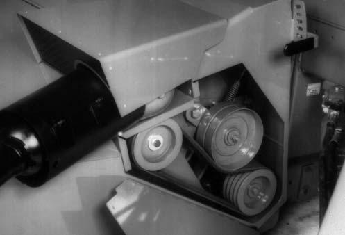
CONDITIONER ROLL DRIVE BELT (Fig. 18)
The Belt on the Disc Conditioner is used to drive the Conditioner Rolls. It is also the overload protection for the Conditioner Rolls.
Belt Tension (Fig. 18)
The Compression Spring, on the Belt Idler, should be set at a 3-5/8″ (92mm) overall length. The Spring-loaded Idler has been designed to protect the Conditioner Roll Driveline; overtightening the Idler will decrease this protection.
Gearbox are ever replaced, Sheave alignment and Conditioner Roll Timing MUST be checked. If Sheaves need to be aligned, contact your Gehl dealer for proper instructions.
Belt Drive Sheave Replacement (Fig. 18)
The Drive Sheave, on the Output Shaft of the Gearbox, can be removed in the following manner:
1.Release the tension on the Belt Idler Spring.
2.Loosen and remove the cap screw, Lock washer and Washer.
3.Using a pulley puller, remove the Sheave from the Gearbox Output Shaft.
To replace the Pulley or install a new one, proceed as follows:
4.MAKE SURE the tapered surfaces of the Gearbox Output Shaft and inside of Pulley hub are clean.
5.Place the Key in the Gearbox Output Shaft.
6.With Key on Shaft, slide Pulley into position on the Shaft.
Secure the Belt Drive Sheave to the Gearbox Output Shaft with the cap screw, Lock washer and Washer. Torque to 80 ft lb (108 Nm).
Cutterbar
Belt Replacement (Fig. 18)
To remove the Belt, use the following steps:
1.Remove the Gearbox Belt Drive Sheave by following details under the Belt Drive Sheave Replacement topic in this chapter.
2.Remove the Belt.
To install a new Belt:
3.Reverse the previous steps to install a new Belt.
4.Place the Belt Idler against the Belt and re-tension the Belt Idler Spring following details under the Belt Tension topic in this chapter. MAKE SURE to re-tension the new Belt after 1/2 hour of operation.
Belt Sheave Alignment
The Belt Sheaves are aligned at the factory and should NOT need adjustment. If the lower Conditioner Roll or
All service to the internal parts of the Cutterbar MUST be carried out by (or under the direction of) an authorized GEHL equipment dealer.
DISCS, KNIVES AND HARDWARE
Discs, Knives, Bolts and Nuts are fabricated from high quality steel and undergo a special heat treatment process to ensure a tough wear resistance and hence a longer life. To avoid creating hazardous out-of-balance forces, ALWAYS replace missing, damaged or worn Blades and Hardware in pairs!
NOTE: Worn or damaged items MUST be replaced immediately with genuine GEHL Service Parts, otherwise all warranty is rendered null and void.
Knife Hardware (Fig. 19)
If any of the following conditions exist, the Blade retaining hardware MUST be replaced. See Fig. 17 for details.
1.When a visible deformation is found.
2.When the locking compound on the Bolt threads has worn away or if the locking compound has become inoperative due to contamination by water, oil or dirt.
3.When wear on the Bolt Head reaches the contact area of the Knife.
4.When a wear groove deeper than 1/8″ (3mm) has formed on the bearing shoulder of the Knife Bolt.
5.When the Contact Washer of the Knife Retaining Nut has lost its elasticity or the Washer becomes loose from the Nut.
6.When wear on the Nut reaches a depth equal to half the height of the Nut.
7.When the retaining hardware has been removed 5 times.
2.For Twisted Blades: The width of a Knife, measured at a distance of 3/8″ (10mm) away from the edge of the Disc, MUST be greater than 3/4 of the nominal width of the Knife. (see Fig. 20) For V-Type Blades: When the tip of the Blade is worn to no less than 3/4″ (19mm). (see Fig. 21)
3.The hole in Knife for retaining Bolt MUST NOT become worn oval by more than 1/16″ (2mm). 1 – 3/8″ (10mm)
2 – MUST Be Greater Than 3/4 of Width of Knife Here
3 – Maximum Out-of-round 1/16″ (2mm)
1 – Acceptable Bolt with Locking Compound Intact
2 – Unacceptable Bolt with Wear Groove
3 – Unacceptable Bolt with Edge Wear
4 – Acceptable Nut with Contact Washer
5 – Unacceptable Nut with Contact Washer Crushed
6 – Unacceptable Nut with Edge Wear
Fig. 19
Removal & Replacement of Twisted Type & V-Type Blades
(See Fig. 20 & 21)
Knives should be inspected systematically each time before the Disc Mower is operated. Failure to replace Knives as required will result in an increase in the risk of accidents, a deterioration in the quality of cut and a risk of damage to the Cutterbar. Both Knives on each Disc MUST be replaced in pairs to maintain balance if any of the following conditions exist (see Figs. 20 and 21):
1.If any sign of cracking is found.
When replacing Knives on the Disc Mower, the following steps MUST be followed:
1.Clean around each self-locking Nut to be removed.
2.Remove self-locking Nuts with a socket. Position Disc to allow Blade Bolt to drop through access hole in front center of Skid Shoe.
3.For Twisted Blades: Fit new Blades or turn Blades to use second cutting edge. MAKE SURE that each Blade is positioned with the small arrow pointing in the direction of rotation of the Disc that the Blade is to be fitted to. For V-Type Blades: Fit new Blades or move Blades to a Disc with opposite rotation to use second cutting edge.
4.MAKE SURE the Bolt is in good condition BEFORE reusing.
5.Torque Locknuts to 90 ft lbs (122 Nm).
Danger
Use ONLY genuine GEHL Service Parts.
NOTE: To ensure proper Blade retention, the retaining hardware MUST be replaced after having been removed 5 times.
Caution
ALWAYS replace damaged Blades. NEVER attempt to straighten a bent Blade.
Disc Removal & Replacement (Fig. 22)
1.Clean around each self-locking Nut in the center of the Disc.
2.Place a block of wood between the Discs so the Discs will NOT rotate when removing the Locknuts.
3.Remove the main Self-locking Nut and Conical Spring Washer.
To remove the cone-shaped outer Right Disc, remove the Plastic Plug on top of the Cone and remove the Self-locking Nut and Conical Spring Washer using a socket and extension.
4.Remove the Disc. If the Disc is tight, pry up with two levers at opposite sides of the Disc.
5.Replace the Disc MAKING SURE that it is rotated 90° from the next Disc and that each Blade is positioned with the small arrow pointing in the direction of rotation of the Disc. Refer to the Service Parts Manual for the proper positioning of the Right and Left Hand Discs. Secure with the Self-locking Nut and Conical Spring Washer MAKING SURE the Conical Spring Washer is positioned with the crown up. Torque to 220 ft lbs (298 Nm).
NOTE: MAKE SURE to replace the Plastic Plug on the cone-shaped outer Discs or dirt will build up inside the cone and cause an out-of-balance condition.
NOTE: If the Disc shows signs of wear after a considerable amount of acreage has been worked, it is advisable to replace it. When the Left Disc needs replacement, contact your dealer’s service department for assistance.
Warning
Do NOT remove Hydraulic Tongue Control Cylinder with Conditioner Header off the ground. Failure to heed can result in death or serious injury.
Hydraulic Lift Cylinders
(Fig. 23)
The Disc Conditioner Lift System consists of a “masterslave” cylinder arrangement, as shown. With a “masterslave”setup, the hydraulic oil, from the rod end of the master cylinder, goes into the base end of the slave cylinder. Because of this arrangement, both cylinders will extend equally, under any load.
With a “master-slave”arrangement, the cylinders can become un-phased such that the machine will raise unevenly (left end higher or lower than the right end). Use the following steps to re-phase the lift cylinders:
1.Completely raise and lower the unit several times, keeping the tractor hydraulic lever engaged, until NO cylinder movement is observed.
NOTE: The cylinders will move very slowly, while equalizing.
2.If the unit is still unequal, proceed to step 3 or 4, depending on the problem.
Warning
BE SURE there is NO pressure in the lines, when loosening the fittings. Hydraulic fluid, under pressure, can penetrate the skin. If injured by escaping fluid, see a doctor at once. Injected fluid MUST BE surgically removed by a doctor familiar with this type of injury or gangrene may result.
3.If the slave cylinder (right) will NOT raise fully, when the master cylinder (left) is fully raised, loosen the fitting into the slave cylinder (bleed point as shown). With the fitting loose, raise the unit, until oil appears at the fitting. Then, re-tighten the fitting and repeat step 1.
4.If the master cylinder (left) will NOT raise fully, when the slave cylinder (right) is fully raised, loosen the fitting that goes into the slave cylinder (bleed point as shown). With the fitting loose, remove approximately 1/2 cup (4 oz) of oil for every one inch of cylinder length difference. Then, re-tighten the fitting and repeat step 1.
1 – Left Side
2 – Master Cylinder
3 – To Tractor
4 – Bleed Point
5 – Slave Cylinder
6 – Right Side
Fig. 23
If the hydraulic cylinders become un-phased frequently, during use, it will be necessary to replace the piston seals in the master cylinder. Only replace the slave piston seal if it is leaking externally.
NOTE: A leaking tractor valve may cause one or both hydraulic cylinders to raise slowly while cutting.
Telescoping Drives
NOTE: For safety reasons, service on the Telescoping PTO Drives should ONLY be performed by (or under the direction of) an authorized GEHL equipment dealer.
Over time, the Telescoping Drive Universal Joints may become worn and noisy and require service. As necessary, remove the Drive(s) from the Disc Conditioner and take them to your dealer.
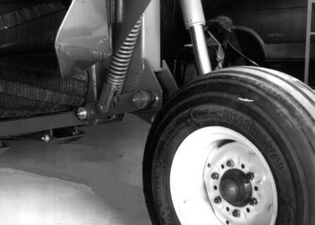
TIRES & WHEELS
The Tires should be inflated to different pressures. Inflate the right side to 36 PSIG (252 kPa) and the left side to 18 PSIG (126 kPa). The Wheel lug nuts should be torqued to 90 ft-lb. The Wheel Bearings should be torqued to 55 ft-lb, while oscillating the Wheel at least 90°, then, the slotted nuts should be backed-off between 1 and 2 cotter pin slots.
NOTE: Under hilly conditions, it is necessary to add a 95% calcium chloride solution to the left tire for additional stability.
Check the Conditioner tire pressures after every 50 hours of operation. Tires should be inflated to 36 PSIG (252 kPa) on the right side and to 18 PSIG (126 kPa) on the left side. Wheel Lug torque should be checked after every 50 hours of operation and tightened to 90 ft lb (124 Nm) torque.
Caution
Our Company does NOT sell replacement Tires. In addition, Tire mounting, repair and replacements should ONLY be attempted by a qualified tire manufacturer’s representative or by properly trained personnel following the tire manufacturer’s instruction. If you do NOT have such instructions, contact your tire dealer or our Company.
Warning
Inflating or servicing tires can be dangerous Whenever possible, trained personnel should be called to service and/or mount tires. In addition, do NOT place your fingers on the tire bead or rim during inflation; serious injury or amputation could result. In any event, to avoid possible death or serious injury, follow the safety precautions below:
• BE SURE the Rim is clean and free of rust.
• Lubricate both the tire beads and rim flanges with a soap solution. Do NOT use oil or grease.
• Use a clip-on tire chuck with a remote hose and gauge which allows you to stand clear of the tire while inflating it.
• NEVER inflate beyond 35 PSI (240 kPa) to seat the beads. If the beads have NOT seated by the time the pressure reaches 35 PSI, deflate the assembly, reposition the tire on the rim, relubricate both parts and re-inflate it. Inflation pressure beyond 35 PSI with unseated beads may break the bead or rim with explosive force sufficient to cause death or serious injury.
• After seating the beads, adjust the inflation pressure to the recommended operating pressure listed.
• Do NOT weld, braze, or otherwise attempt to repair and use a damaged rim.