26 minute read
Chapter 8 SERVICE & STORAGE

Generalinformation
Warning
BEFORE performing any service on the Telescopic Loader, unless expressly instructed to the contrary, exercise the MANDATORY SAFETYSHUTDOWN PROCEDURE (Safety chapter). After service has been performed, BE SURE to restore all guards, shields and covers to their original positions BEFORE resuming machine operation.
When a problem occurs, don’t overlook simple causes such as an empty fuel tank. Check for leaks and broken connections. Make note of any specific problem symptoms, noises, etc. and contact your local Gehl dealer.
IMPORTANT: Always dispose of waste lubricating oils, anti-freeze and hydraulic fluids according to local regulations or take them to a recycling center for disposal. DO NOT pour them onto the ground or into a drain.
Dealer Services
The following areas of internal components service replacement and operating adjustments should only be attempted by (or under the direction of) an authorized GEHLTelescopic Loader dealer.
NOTE: All service routines, with the exception of those described under the “Dealer Services” topic, are owner-operator responsibilities. All operator services described under the subtopics are also referred to on a decal located inside the small rear access door of the operator’s station. Refer to the LUBRICATION chapter of this manual for lubrication information.
NOTE: This SERVICE & STORAGE chapter details procedures to follow for making routine maintenance checks, adjustments and replacements. The majority of the procedures are also referred to in the MAINTENANCE chapter of this manual. For engine related adjustments and servicing procedures, refer to the engine manual provided.
Precautions
DO NOTperform any maintenance or repair without the owner’s prior authorization. Allow only trained personnel to service the machine.
WARRANTYrepairs can only be done by a GEHL dealer. He will know what portions of the machine are covered under the terms of the GEHLWarranty and what portions are covered by other vendor OEM warranties.
IMPORTANT: DO NOT service or repair major components, unless authorized to do so by your Gehl dealer. Any unauthorized repair will void the warranty.
Power Train Components
The engine and transmission are coupled together with a transfer case. All service routines, related to the internal components are precise and critical to proper power train operation. The axle differential and planetary ends are also sophisticated assemblies which require special know-how and tools for servicing.
IMPORTANT: If any area of power train componentry is suspected of faulty operation, contact your Gehl dealer for further assistance.
Hydraulic System Components
Valves, pumps, motors and cylinders are also sophisticated assemblies which require special know-how and tools for servicing. All cylinders are approprietly designed with particular strokes, diameters, checks and hose connection provisions unique to the machine application requirements. Aschematic (located at the end of this manual) can be used as a guide for service reference, as required.
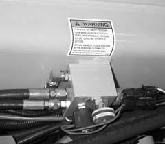
Warning
Tilt, lift, extend, and leveling cylinders have counterbalance valves. These valves keep hydraulic fluid from entering or exiting the cylinders while not being used, and are under extremely high pressure. Before removing one of these valves, you ARE REQUIRED to call Gehl Service. Failure to do so may result in serious injury or death.
Internal service on any of these components should only be attempted by (or under the direction of) an authorized GEHLTelescopic Loader dealer. WARRANTYrepairs can only be done by a GEHLdealer.
He will know what portions of the machine are covered under the terms of the GEHLwarranty and what portions are covered by other vendor warranties.
Electricalcomponents
An electrical system schematic is provided which includes instrumentation, electrical components and switch connections. It is located at the end of this manual and can be used as a guide for service reference, as required.
Operator Services
Some of the operator related services will require access to components located inside the superstructure under shields, hoods and covers. The reference chart on this page notes components accessed in each particular area.
Access To Components Reference Chart
Axle (underside)
Engine Transmission
Transfer Case
Drive Shafts
Solenoid valves (rear & middle)
Main Control Valve (rear)
Muffler (underside)
Air Cleaner
Battery
Radiator
Brake Valve (dash area)
Travel Controls (dash area)
Boom Controls (right side)
Hydraulic Test Ports (pump)
Hour Meter
Electric Switches (dash area)
Electric Switches (right side)
Hydraulic Pump
Air Conditioner (rear)
Fuse Box (rear)
Hydraulic Filter (underside)
Warning
DO NOT smoke or allow any open flames in the area while checking or servicing hydraulic, battery or fuel systems; all contain highly flammable liquids or explosive gases which can cause an explosion or fire if ignited. Wear a face shield when you disassemble spring-loaded components or work with battery acid. Wear a helmet or goggles with special lenses when you weld or cut with a torch.
When working beneath a raised machine, always use blocks, jack-stands or other rigid and stable supports. Wear appropriate protective clothing, gloves, shoes. Keep feet, clothing, hands and hair away from moving parts.
Always wear safety glasses or goggles for eye protection from electric arcs from shorts, fluids under pressure, and flying debris or loose material when the engine is running or tools are used for grinding or pounding.
NEVER weld on bucket, forks, boom, support frame or ROPS/FOPS without the consent of the manufacturer. Special metals may be used which require special welding techniques, or have a design which should not have weld repairs. NEVER cut or weld on fuel lines or tanks.
If repair welding is ever required, BE SURE to attach the ground (-) cable from the welder as close as possible to the area to be repaired. Also, remove positive (+) battery terminal connection before welding.
Choose a clean, level work area. Be sure you have sufficient room, clearances, and adequate ventilation. Clean the walking and working surfaces. Remove oil, grease and water to eliminate slippery areas. Utilize sand or oil absorbing compound, as necessary, while servicing the Telescopic Loader.
Before starting inspection and repair, move the machine onto a level surface, shut down engine, and release all hydraulic pressure. Always block the boom securely, or lower it to full ground contact. Place all controls in neutral.
Block the wheels. Turn the master disconect switch key to shut down power from the battery and remove the ignition key. Remove only guards or covers that provide needed access. Wipe away excess grease and oil.
NEVER weld on attachment tools, boom support frame or overhead guards without the consent of the manufacturer. Special metals may be used which require special welding techniques or have a design which should not have welded repairs. NEVER cut or weld on fuel lines or tank.
Excessively worn or damaged parts can fail and cause injury or death. Replace any cracked or damaged part. Care should be taken to assure that all replacement parts are interchangeable with original parts and of equal quality.
Use care not to damage machined and polished surfaces. Clean or replace all damaged or painted over plates and decals that cannot be read.
Warning
NEVER leave guards off or access doors open when the machine is unattended. Keep bystanders away if access doors are open.
After servicing, check the work performed, no parts left over, etc. Install all guards, covers and turn back the master disconnect switch key to activate battery power.
Service Every 10 Hours or Daily
Check Fueltank Level
After operation each day, the fuel tank should be filled to prevent water from condensing in the tank. To fill, remove the filler cap and add fuel.
Adrain plug is provided in the bottom of the fuel tank for removing condensation and other foreign materials. Open the plug and allow water and fuel to drain into a container until only clear fuel is flowing from the tank.
Check Fuelfilter
NOTE: The fuel filter will require occasional replacement to maintain a clean and adequate fuel flow for maximum engine horsepower. The frequency of filter replacement will be determined by the cleanliness of available fuel, the care used in storing fuel supplies and the operating conditions in which the machine is used.
Small amounts of water can be drained from the fuel filter. The drain plug should be removed weekly to drain off water accumulation until clear fuel is flowing from the outlet.
Check Engine Oillevel
With the machine on level ground, and the engine stopped for ten minutes or more, raise the engine hood and remove the engine dipstick. Wipe it clean, re-insert it and remove to obtain a reading. If the oil level is down, or below the ADD mark, fill with the required amount of oil to bring the level to the FULLmark. See the LUBRICATION chapter for the type of oil to use.
Check Transmission Oillevel
The machine must be on level ground and make sure the boom is lowered and completely retracted. With the engine and transmission at operating temperature, park brake on, F-N-R lever in neutral and the engine at low idle, raise the engine hood remove the dipstick located on the front backwall and check the oil level. If the oil level is down, or below the ADD mark, fill into the tube with the required amount of oil to bring the level to the FULLmark. See the LUBRICATION chapter for the type of oil to use.
Check Radiator Coolant Level
Warning
DO NOT remove the radiator cap when the engine is running hot or overheated. Coolant is extremely hot and under pressure and it can burn your skin. Allow sufficient time for the radiator to cool BEFORE relieving the pressure and removing the radiator cap.
quality water and supplemental coolant additives (SCAs) suitable for heavy duty diesel engines. See your engine manual for additional information. Replace the radiator cap securely.
NOTE: If the engine is operated with a loose radiator cap, the pressure bypass will not work and the engine will run hot.
Check Hydraulic Oillevel
The machine must be on level ground and make sure the boom is lowered and completely retracted. With the engine stopped for ten minutes or more, raise the engine hood. Remove the dipstick located beside the hydraulic oil fill tube cap. If the oil level is down, or below the ADD mark, fill with the required amount of oil to bring the level to the FULLmark. See the Lubricants chapter for the type of oil to use.
IMPORTANT: Be careful when removing the reservoir filler cap so that no dirt or other foreign matter enters the hydraulic system while the cap is removed. DO NOT OVERFILL.
Check Tire Pressures
Proper tire pressure should be maintained equally for all four tires to enhance operating stability and extend tire life.
When installing tires on the machine, be sure that all tires are of the same size and style. ALWAYS replace tires with the same size furnished as original equipment. Replacement tires must be purchased locally.
Check the tire pressure “cold”. All 12 ply tires should be inflated to 70 PSI (480 kPa).
NOTE: If the tires have been filled with water or calcium chloride for ballast, a calcium chloride tire pressure gauge MUST be used to check the tire pressure.
When removing tires follow industry safety practices. Deflate completely prior to removal. Following assembly of the tire on the rim, use a safety cage or restraining device while inflating.
Check Wheelnut Torque
With the machine on level ground, remove the radiator cap. If the coolant level is below the filler neck, add a low silicate ethylene glycol base coolant mixed with
On NEWmachines, or anytime wheel has been removed, re-torque until 450 ft-lbs (610 Nm) is maintained.
Warning
NEVER service tires if the bead lock ring appears loose. Clear the area and call for professional tire repair help.
Inflating or servicing tires can be dangerous. Whenever possible trained personnel should service and mount tires. To avoid possible death or serious injury, follow the safety precautions below: tions or noises? Are any hose or fitting connections leaking? Is the engine exhaust color normal (light grey)?
1. BE SURE the rim is clean and free of rust.
2.Lubricate both the tire beads and rim flanges with a soap solution. DO NOT use oil or grease.
3.DO NOT place your fingers on the tire bead or rim during inflation. Use a clip-on tire chuck with a remote hose and gauge, which allows you to stand clear of the tire while inflating it.
4. NEVER inflate beyond 35 PSI (240 kPa) to seat the beads. If the beads have NOT seated by the time the pressure reaches 35 PSI, deflate the assembly, reposition the tire on the rim, relubricate both parts and re-inflate. Inflation pressure beyond 35 PSI with unseated beads may break the bead or rim with explosive force sufficient to cause death or serious injury.
5.After seating the beads, adjust the inflation pressure to the recommended operating pressure listed.
6.DO NOT weld, braze, or otherwise attempt to repair and use a damaged rim.
Warning
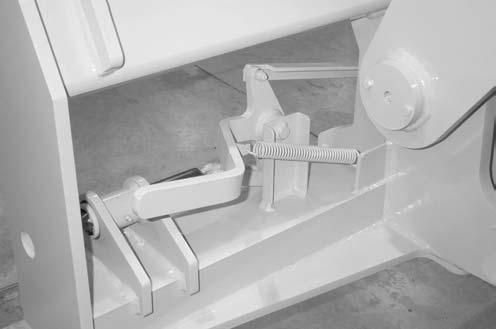
Manufacturers of push-pull control cables advise taking the following operation and maintenance precautions:
Do not adjust the control cable with the engine running.
Agradual or sudden increase in the no-load friction (cable disconnected at both ends) of a control cable is an indication of a pending or present performance problem. The control cable should be replaced.
Agradual or sudden decrease in the useable travel is a indication of a pending or present performance problem. The cable should be replaced.
Control cables that have moisture inside of them and/or have frozen should be replaced. Do not apply heat to thaw or dry control cables.
Control cable are lubricated for the life of the control cable. Do not remove the seals or lubricate the control cable.
Control cables are designed to be nonrepairable. Do not attempt to repair control cables.
Failure to heed could result in death or serious injury.
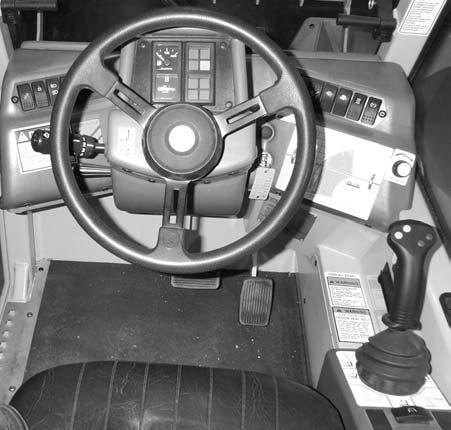
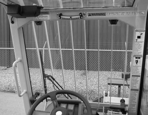
Check Instruments Operation
Allow the engine to warm up for about five minutes before beginning operation. Indicator lamps should be OFF and gauges should register normal readings. Tilt the frame from side to side with the sway control and note the angle indicator movement.
CHECK GENERALMACHINE OPERATION & CONDITION
Are any decals missing or damaged? Are all guards, shields and covers in place? Do all controls function smoothly and properly? Are there any abnormal vibra-
Service Every 50 Hours or Weekly
Refer to the LUBRICATION chapter of this manual for weekly grease fitting locations and other related details.
100 Hours (New Machine Only)
The following initial oil and filter changes should be made at this time on a new machine. Thereafter these changes should be made at the regular maintenance schedule listed. Refer to those schedules for procedures necessary.
Engine Oil & Filter (250 Hours)
Transmission Oil & Filter(1000 Hours)
Hydraulic Return Filter Element(1000 Hours)
Service Every 250 Hours or Quarterly
NOTE: Perform all other service requirements up to this point as well as the following.
Check Axle Oillevels
Differential
NOTE: The Telescopic Loader should be on a level surface for this procedure.
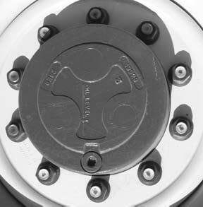
Remove the oil level check/fill plug (see illustration) Oil should overflow the hole. If low, fill until oil overflows the hole. When oil overflows, replace the plug, wait 10 to 15 minutes and repeat the fill procedure. Continue this process until the differential is full. See the LUBRICATION chapter of this manual for the proper oil specification. Replace the oil level check/fill plug.
The planetary hubs have one plug each used for filling and draining (see illustration). For checking the level and filling, position the Wheel until the plug is horizontal. Remove the fill plug. If oil does not run out, add oil until it overflows. Check the remaining hubs the same way. Refer to the oil specifications found in the LUBRICATION chapter of this manual.

Planetary Oil Check/Fill Plug
Differential Oil Check Plug
Planetary Hubs
NOTE: The planetary hubs can be checked without jacking up the machine.
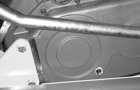
Check Transfer Oillevel
Remove the oil level check plug (see illustration on page 56). Oil should flow from the hole. If low, remove the breather cap located on the front side of the transfer case. Fill with the proper oil until oil flows from the check hole. Replace the check plug and the breather cap.
Change Fuelfilter
The frequency of filter replacement will be determined by the cleanliness of available fuel, the care used in storing fuel supplies and the operating conditions in which the machine is used.
NOTE: For proper replacement procedures refer to the engine manual for your machine.
After fuel filter replacement, bleed the air out of the fuel system following the procedures in the engine manual.
Fuel Bleeding Procedures
When the fuel filter is removed and replaced, or the engine runs out of fuel, air must be bled from the system. Refer to the engine manual relative to proper bleeding procedures.
If the engine still will not start, consult your nearest authorized engine dealer.
Warning
NEVER service the fuel system while smoking, while near an open flame, or after the engine has been operated and is hot.
NOTE: Only an authorized engine dealer can perform WARRANTYService on the engine.
Diesel Fuel Injectors
Whenever faulty or plugged injectors are indicated, see your nearest authorized engine dealer.
Diesel Injection Pump Timing
Whenever injection pump timing, or other pump service is indicated by abnormal engine operation, contact your nearest engine dealer.
Warning
Escaping diesel fuel under pressure can have sufficient force to penetrate the skin. Before applying pressure to the fuel system, BE SURE all connections are tight and lines and hoses are NOT damaged. Use a piece of wood or cardboard to search for suspected leaks. If injured by escaping fuel, see a doctor familiar with this type of injury at once or gangrene may result.
CHANGE ENGINE OIL& FILTER
Change the engine oil and filter using the following procedure:
1.With the engine warm, remove the crankcase drain plug. Some plugs are equipped with a magnet to gather metal particles. Completely clean and flush away all metallic filings from the plug and re-install it.
IMPORTANT: DO NOT discharge oil onto ground. Catch and dispose of per local waste disposal regulations.
2.The engine oil filter should be changed at every oil change interval. Remove and discard the throw away filter canister. Wipe the gasket sealing area of the block with a clean cloth.
NOTE: Your OEM engine oil filters have special by-pass valves built in. Use only genuine OEM engine replacement filters.
3.Apply a thin coat of clean oil to the new oil filter gasket. Spin tighten. Refill the crankcase with new oil. Follow specifications in the LUBRICATION chapter for type and viscosity of new oil.
4.After new oil has been added, run the engine at idle speed until the oil pressure light is OFF. Check for leaks at the filter and drain plug. Re-tighten only as much as necessary to eliminate leakage.
Check The Battery
The battery furnished in the machine is a 12 volt, wetcell battery.
Warning
Explosive gas is produced while a battery is in use or being charged. Keep flames or sparks away from the battery area. Make sure battery is charged in a well-ventilated area.
NEVER lay a metal object on top of a battery as a short circuit can result.
Battery acid is harmful on contact with skin or fabrics. If acid spills, follow these firstaid tips:
1.IMMEDIATELYremove any clothing on which acid spills.
2.If acid contacts the skin, rinse the affected area with running water for 10 to 15 minutes.
3.If acid comes in contact with the eyes, flood the eyes with running water for 10 to 15 minutes. See a doctor at once. NEVER use any medication or eye drops unless prescribed by the doctor.
4.To neutralize acid spilled on the floor, use one of the following mixtures: a.1 Pound (0.5 kg) of baking soda in 4 quarts (4 liters) of water. b.1 Pint (0.4 liters) of household ammonia in 4 quarts (4 liters) of water.
Whenever battery is removed from the unit, BE SURE to disconnect the negative (-) battery terminal connection cable first.
Handling Battery Safely
The top of the battery must always be kept clean. Clean the battery with a brush dipped in an alkaline solution (ammonia or baking soda and water). After the foaming has stopped, flush the top of the battery with clean water. If the terminals and cable connection clamps are corroded or have a buildup, disconnect the cables and clean the terminals and clamps with the same alkaline solution.
NOTE: The battery in this machine is warranted by the supplier. See the punch tag on the top of the battery for warranty information.
Jump Starting
If the battery becomes discharged or does not have enough power to start the engine, use jumper cables and the following procedure to jump-start the engine.
IMPORTANT: BE SURE that the jumper battery is also a 12 volt D. C. battery, and the vehicle used for jump starting has a negative ground electrical system.
Warning
The ONLYsafe method for jump-starting a discharged battery is for TWO PEOPLE to perform the following procedure. The second person is needed for removing the jumper cables so that the operator does not have to leave the operator’s compartment while the engine is running. NEVER make the jumper cable connections directly to the starter solenoid of either engine. DO NOT start the engine from any position other than the operator’s seat, and then ONLYafter being sure all controls are in “neutral”.
Closely follow the jump-start procedures, in the order listed, to avoid personal injury. In addition, wear safety glasses to protect your eyes, and avoid leaning over the batteries while jump-starting.
DO NOT attempt to jump-start the machine if the battery is frozen, because this may cause it to rupture or explode.
1.Turn the keyswitches on both vehicles to OFF. Be sure that both vehicles are in “Neutral” and NOT touching.
2.Connect one end of the positive (+) jumper cable to the positive (+) battery terminal on the disabled machine first. DO NOTallow the jumper’s positive (+) cable clamps to touch any metal other than the positive (+) battery terminals. Connect the other end of the positive jumper cable to the jumper battery positive (+) terminal.
3.Connect one end of the negative (-) jumper cable to the jumper battery negative (-) terminal.
4.Make the final negative (-) jumper cable connection to the disabled Telescopic Loader’s engine block or frame (ground) - NOTto the disabled battery negative post. If making the connection to the engine, keep the jumper clamp away from the battery, fuel lines, or moving parts.
NOTE: Twist the jumper cable clamps on the battery terminals to insure a good electrical connection.
5.Proceed to start the machine. If it does not start immediately, start the jumper vehicle engine to avoid excessive drain on the booster battery.
6.After the machine is started and running smoothly, have the second person remove the jumper cables (negative (-) jumper cable, first) from the jumper vehicle battery, and then from the disabled machine while insuring NOTto short the two cables together.
Allow sufficient time for the alternator to build-up a charge in the battery before attempting to operate the machine or shut the engine off.
NOTE: If the battery frequently becomes discharged, have the battery checked for possible dead cell(s), or troubleshoot the entire electrical system for possible short circuits or damaged wire insulation.
CHECK BOOM SLIDE PADS WEAR & CLEARANCE
This boom is equipped with special nylon low friction slide pads between the telescopic sections (see illustration). These are pre-greased and initially worn-in at the factory. Normally greasing is not required, except for maintaining a light film of grease on the pad tracking areas of the boom sections. An exception would be if a boom section has been replaced.
Visually check for loose pad bolts. The bolts are torqued to 30 ft-lb (40 Nm). If the bolts are re-torqued at any time, Locktite thread lock must be re-applied to the bolts.
If the boom starts to chatter under load, grease the slide pads and wipe off the excess. If a top or side slide pad shows excessive wear, loosen bolts. Insert shims to each side or top and bottom for even distribution of clearance. Re-apply Loctite® thread lock to the bolts and re-torque to 30 ft-lbs (40 Nm). Bottom slide pads should be replaced when the thickness is worn down to 3/8” (9.5 mm).
Warning
Failure to maintain proper slide pad clearance and thickness could cause damage to the boom, resulting in sudden boom failure.
1.Remove the drain plug and drain out old oil. Replace the drain plug.
IMPORTANT: DO NOT discharge oil onto ground. Catch and dispose of per local waste disposal regulations.
2.Remove and discard the oil filter. Wipe the sealing surface on the transmission with a clean cloth. Apply a thin coat of clean oil to the new oil filter gasket. Spin tighten.
3.Refill the transmission with new oil as shown in the Lubrication chapter of this manual.
IMPORTANT: DO NOT OVERFILL! lf the oil level is too high, oil foaming, excessively high oil temperature and oil leakage at the seal could result.
4.Start and run the machine long enough for the oil to circulate and warm slightly. Recheck the level with the dipstick.
Change Radiator Coolant
Drain, flush and refill the cooling system as follows:
IMPORTANT: DO NOT discharge coolant onto ground. Catch and dispose of per local waste disposal regulations.
1.Loosen the radiator cap to its stop. This will release any system pressure. Remove the cap when all pressure is bled off.
Service Every 1000 Hours or Yearly
NOTE: Perform all other service requirements up to this point, as well as the following.
CHANGE TRANSMISSION OIL& FILTER
Operate the machine long enough to warm up the transmission oil. Shut down the engine. Access to filter and drain plug is from underneath the machine. Proceed as follows:
Remove the radiator cap only when the engine is cool, or painful burns could result.
2.Open the radiator drain cock. Remove the water jacket drain plug from the engine block. When all coolant is drained, flush the system with clean fresh water. Allow the flush to drain completely.
3.Replace all drain plugs and tighten the radiator drain cock. Clean out the cooling fins in the radiator with water pressure or steam.
IMPORTANT: Fill the cooling system with a low silicate ethylene glycol base coolant mixed with quality water and supplemental coolant additives (SCAs) suitable for heavy duty diesel engines. See your engine manual for additional information.
4.Inspect the radiator cap seal before installing it. Replace it if it appears defective. The 10 PSI (70 kPa) pressure cap and engine thermostat work in conjunction with each other to maintain proper engine cooling.
NOTE: Check the engine temperature lamp every minute or two after coolant has been changed. Air pockets can form, and it may be necessary to refill the cooling system after a short period of use, as the air will naturally bleed out of the system.
Change Hydraulic Return Filter Element
This element is a cartridge type accessible from underneath the chassis. Initial replacement is after the first 100 hours. Unscrew the filter cover and remove. Slide off the old element and discard. Insert the new element onto the housing. Replace the cover.
Warning
Lower the boom to the ground when servicing the hydraulic system.
IMPORTANT: This filter is equipped with a restriction sensor. If the dash indicator light comes on, the element should be replaced.
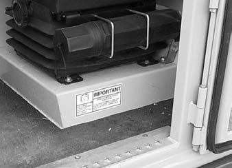
Change Air Filter Element
This air filter contains a single dry element. This element has a restriction indicator sensor. In extreme dusty operation, a dash light will indicate that the element should be cleaned or replaced.
1.Unsnap the clasps to release the end cap. Remove the end cap. Wipe the end cap and baffle completely clean.
2.The filter element fits tightly over the body outlet tube, creating the critical seal on the inside diameter of the filter end cap. Remove the element gently to reduce the amount of dust dislodged. There will be some initial resistance, similar to breaking the seal on a jar. Gently move the end of the element up and down and side to side or twist to disengage the seal.
3.Gently pull the element off the outlet tube and out of the housing. Avoid knocking the element against the housing. Dirt accidentally transferred to the inside of the outlet tube will reach the engine and cause wear.
4.Clean the sealing surface and the inside of the outlet tube. Dust on the outer diameter could hinder proper element sealing. Be careful not to damage the element sealing area of the tube.
Astreak of dust on the clean air side of the old element indicates a leakage problem. Be sure to remove the cause before installing a new element.
5.Inspect the new element for possible damage, especially on the sealing area. This area will distribute the sealing pressure evenly onto the outlet tube as the element is installed.
IMPORTANT: NEVER use an element that is damaged. Severe engine wear and eventual failure can result if dirt gets through a hole in the element.
Install the new element. To complete a tight seal, apply firm pressure at the outer rim of the element, not the flexible center.
6.Reassemble the end cap to housing. end cap pressure is not necessary to compress the element seal.
NOTE: Keep spare elements on hand to eliminate down time.
CHANGE AXLE DIFFERENTIAL & PLANETARYOIL Differential
1.Remove the drain plug and drain out the old oil. Replace the drain plug.
IMPORTANT: DO NOT discharge oil onto ground. Catch and dispose of per local waste disposal regulations.
2.Remove the check/fill plug and fill the differential with oil as specified in the LUBRICATION chapter. When the oil overflows the oil level/fill hole, replace the plug. Wait 10 to 15 minutes and repeat this process until the axle is full. Repeat the procedure with the other axle.
CHECK ALTERNATOR & FAN BELT CONDITION
Planetary Oil
Check/Fill Plug in Check/Fill Position
Drain Plug
Axle Planetary Hubs
Differential Oil
Check/Fill Plug
The hubs have one plug each used for draining and filling (see illustration).
1.Position the wheel until the drain plug points down. This allows the oil to drain out.
IMPORTANT: DO NOT discharge oil onto ground. Catch and dispose of per local waste disposal regulations.
Refer to the engine manual relative to proper belt tension adjustment and replacement procedures. If the belt shows wear or cuts, it should be replaced. Order replacement belt from your engine dealer.
Check Exhaust System
Examine the muffler and tail pipe for possible holes. Re-tighten any loose clamps and make sure the manifold outlet gasket is not leaking.
Service Every 2000 Hours or Every Two Years
NOTE: Perform all other service requirements up to this point, as well as the following.
Check Hydraulic System Relief Pressures
Pressure settings for relief valves are pre-set at the factory. Asingle test port is provided from the hydraulic pump.
Planetary Oil
Check/Fill Plug in Drain Position
2.Re-position the hub so the drain plug points horizontal. Fill with fresh oil as specified in the LUBRICATION chapter. Re-install the drain/fill plug. Repeat this procedure on the three remaining hubs.
Before conducting any test port pressure checks, check the engine RPM. Engine speed must be 950 to 1000 RPM at idle and 2690 to 2750 high idle RPM.
Steering Relief Pressure
Plug a 3000 PSI (207 Bar) oil or liquid filled gauge in the main/steering test port. Cramp the steering full to the right or left. The gauge should read 2500 PSI (172 Bar).
Check Main Relief Pressure
With the gauge in the main/steering test port and the boom extended, retract the boom fully. The gauge should read 3000 PSI (207 Bar).
CHANGE HYDRAULIC RESERVOIR OIL& STRAINER
Clean all dirt and debris from around the area where the hydraulic system suction (large) hose connects to the wall of the reservoir.
1.Remove the drain plug and drain out all used oil. Wash or blow off all collected particles from the magnetic drain plug.
IMPORTANT: Do NOT discharge oil onto ground. Catch and dispose of per local waste disposal regulations.
2.Disconnect the suction hose and remove the sump strainer from inside the reservoir. Inspect the strainer. If it shows any damage, holes, etc. it should be replaced. Otherwise wash it clean with an industrial solvent, dry with a rag and coat with fresh hydraulic oil.
3.Flush out the bottom of the tank with clean hydraulic oil. Re-install the drain plug, strainer and reconnect the suction hose.
4.Fill the tank with fresh oil. Follow specifications found in LUBRICATION chapter of this manual.
Warning
Escaping hydraulic oil under pressure can have sufficient force to penetrate the skin. Before applying pressure to the hydraulic system, be sure all connections are tight and lines and hoses are not damaged. Use a piece of wood or cardboard to search for suspected leaks. If injured by escaping hydraulic oil, see a doctor familiar with this type of injury at once or gangrene may result.
IMPORTANT: Hydraulic fluid and filters should be replaced any time contamination is present before the normally scheduled change.
Change Transfer Case Oil
Raise the engine hood for access.
1.Remove the drain plug from underneath to drain out old oil.
IMPORTANT: DO NOT discharge oil onto ground. Catch and dispose of per local waste disposal regulations.
2.Remove the breather cap located on the front sideof the transfer case. Fill with fresh oil until it flows from the check hole. Follow specifications found in the LUBRICATION chapter of this manual.
Storage
If the Telescopic Loader will not be operated for a long period of time, prepare and store it using the procedures as follows.
Before Storage
Perform the following prior to placing the machine in storage:
1Wash off the entire machine.
2.Lubricate all grease fittings as described in the LUBRICATIONchapter of this manual.
3.Change engine oil as outlined in the SERVICE & STORAGEchapter of this manual.
4.Apply grease to all exposed hydraulic cylinder rod areas.
5.Disconnect the battery cable clamps and cover the battery or remove the battery from the machine and store it separately.
6.If the ambient temperature (at any time during the storage period) is expected to drop below freezing, make sure the engine coolant is either completely drained from the radiator and engine block or that the amount of anti-freeze in it is adequate to keep the coolant from freezing. Refer to the separate engine manual provided for anti-freeze recommendations and quantities.
During Storage
1.About once each month, connect the battery and check all fluid levels to make sure they are at the proper level before starting the engine.
2.Start the engine and allow it to run until it warms up and then move the machine a short distance to help relubricate the internal parts. Run the engine until the battery has a chance to recharge and then shut it off.
IMPORTANT: If it is desired to operate the hydraulic cylinders at this time, BE SURE to wipe the protective grease (and any adhering dirt) from the cyllnder rods prior to starting the engine. After operating, BE SURE to re-coat the cylinder rods with grease if the machine is to be returned to storage.
After Storage
After removing the machine from storage and BEFORE operating it, perform the following:
1.Change engine oil and filter to remove condensation and residues.
2.Wipe off grease from cylinder rods.
3.Lubricate ALLgrease fittings.
4.Review and re-familiarize yourself with all safety precautions as outlined in the SAFETYchapter of this manual.
5.Follow the starting and warm-up procedures as outlined in the OPERATION& ADJUSTMENTS chapter of this manual.
Chapter 9
Decallocations
New Decalapplication
Caution
ALWAYS read and follow the safety rules and information shown on decals. If any decals are damaged or unreadable, or if the unit is repainted, the decals must be replaced. If repainting, BE SURE that all decals which apply to your machine are affixed in their proper locations.
Decal locations information is provided to assist in the proper selection and application of new decals, in the event the original decal(s) become(s) damaged or the machine is repainted.
For correct replacement of decal(s) compare the location illustrations to your machine before starting to refinish the unit. Check-off each required decal using the illustration reference number to find the part number, description and quantity in the list. Refer to the appropriate illustration(s) for replacement location(s).
NOTE: Refer to the “Safety” chapter of this manual for the specific information provided on the various safety decals.
Before applying the new decals, surfaces must be free from dirt, dust, grease and other foreign material. To apply a solid-formed decal, remove the smaller portion of the decal backing paper and apply this part of the exposed adhesive backing to the clean surface while maintaining proper position and alignment. Slowly peel off the other portion of the backing paper while applying hand pressure to smooth-out decal surface. To apply a die-cut decal, first remove the backing paper. Then, properly orient and position the decal onto the clean mounting surface. After the decal is firmly applied and smoothly pressed down, remove the front covering paper.
Paint Finish
Use this list to order paint for refinishing:
906213One Gal. Yellow 906317One Gal. Charcoal Grey 906323One Qt. Charcoal Grey 9062146 (12 oz. Spray Cans) Yellow
Decal Kits
L500442Decal Kit, AL-730
Kit, AL-730 Load Charts
NOTE: Decals may be purchased in a kit or individually.
REF.DESCRIPTIONAL-730
01WARNING - PARK BRAKEL65925
02WARNING - FASTEN SEATBELTL65440
03DANGER - PERSONALINJURYL65928
04WARNING - ROLLOVER HAZARDL65930
05WARNING - CARRYLOAD LOW093475

06DANGER - HI-VOLT/MOVING PARTSL70307 07WARNING - TILTHAZARD/GENL. OPER.L70306
11FUSES/RELAYS REFERENCEL71530
12MAINTENANCE CHARTL71617
13OPERATOR MANUALINSIDEL65922

14WARNING - NO RIDERSL65932
15DIFFERENTIALLOCK (optional)L71561
16TEMPERATURE CONTROL(optional)L70503
17DECALKIT, AL-730 LOAD CHARTSL500443

DECALLOCATIONS - LEFT SIDE, TRUCK FRAME


- RIGHT SIDE, TRUCK FRAME