14 minute read
PLUGINFILLAND CHECKPOSITION.


NOTE: Only an authorized engine dealer can perform WARRANTYService on the engine.
Diesel Fuel Injectors
Whenever faulty or plugged injectors are indicated, see your nearest authorized engine dealer.
Diesel Injection Pump Timing
Whenever injection pump timing, or other pump service is indicated by abnormal engine operation, contact your nearest engine dealer.
Warning
Change Fuelfilter
The frequency of filter replacement will be determined by the cleanliness of available fuel, the care used in storing fuel supplies and the operating conditions in which the machine is used.
NOTE: For proper replacement procedures refer to the engine manual for your machine.
Warning
NEVER service the fuel system while smoking, while near an open flame, or after the engine has been operated and is hot.
After fuel filter replacement, bleed the air out of the fuel system following the procedures in the engine manual.
Fuel Bleeding Procedures
When the fuel filter is removed and replaced, or the engine runs out of fuel, air must be bled from the system. Refer to the engine manual relative to proper bleeding procedures.
If the engine still will not start, consult your nearest authorized engine dealer.
Escaping diesel fuel under pressure can have sufficient force to penetrate the skin. Before applying pressure to the fuel system, BE SURE all connections are tight and lines and hoses are NOT damaged. Use a piece of wood or cardboard to search for suspected leaks. If injured by escaping fuel, see a doctor familiar with this type of injury at once or gangrene may result.
Change Engine Oiland Filter
Change the engine oil and filter using the following procedure:
1.With the engine warm, remove the crankcase drain plug. Some plugs are equipped with a magnet to gather metal particles. Completely clean and flush away all metallic filings from the plug and re-install it.
IMPORTANT: DO NOT discharge oil onto the ground. Catch and dispose of per local waste disposal regulations.
2.The engine oil filter should be changed at every oil change interval. Remove and discard the throw away filter canister. Wipe the gasket sealing area of the block with a clean cloth.
NOTE: Your OEM engine oil filters have special by-pass valves built in. Use only genuine OEM engine replacement filters.
3.Apply a thin coat of clean oil to the new oil filter gasket and spin tighten. Refill the crankcase with new oil. Follow specifications in the LUBRICATION chapter for type and viscosity of new oil to put in.
4.After new oil has been added, run the engine at idle speed until the oil pressure light is OFF. Check for leaks at the filter and drain plug. Re-tighten only as much as necessary to eliminate leakage.
Check The Battery
The battery furnished with this machine is a 12 volt, wet-cell battery.
Handling Battery Safely
The top of the battery must always be kept clean. Clean the battery with a brush dipped in an alkaline solution (ammonia or baking soda and water). After the foaming has stopped, flush the top of the battery with clean water. If the terminals and cable connection clamps are corroded or have a buildup, disconnect the cables and clean the terminals and clamps with the same alkaline solution.
NOTE: The battery in this machine is warranted by the supplier. See the punch tag on the top of the battery for warranty information.
Jump Starting
If the battery becomes discharged or does not have enough power to start the engine, use jumper cables and the following procedure to jump-start the engine.
Warning
Explosive gas is produced while a battery is in use or being charged. Keep flames or sparks away from the battery area. Make sure battery is charged in a well-ventilated area.
NEVER lay a metal object on top of a battery as a short circuit can result.
Battery acid is harmful on contact with skin or fabrics. If acid spills, follow these firstaid tips:
1.IMMEDIATELYremove any clothing on which acid spills.
2.If acid contacts the skin, rinse the affected area with running water for 10 to 15 minutes.
3.If acid comes in contact with the eyes, flood the eyes with running water for 10 to 15 minutes. See a doctor at once. NEVER use any medication or eye drops unless prescribed by the doctor.
4.To neutralize acid spilled on the floor, use one of the following mixtures: a.1 Pound (0.5 kg) of baking soda in 4 quarts (4 liters) of water. b.1 Pint (0.4 liters) of household ammonia in 4 quarts (4 liters) of water.
Whenever battery is removed from the unit, BE SURE to disconnect the negative (-) battery terminal connection cable first.
IMPORTANT: BE SURE that the jumper battery is also a 12 volt D. C. battery, and the vehicle used for jump starting has a negative ground electrical system.
1.Turn the keyswitches on both vehicles to OFF. Be sure that both vehicles are in “Neutral” and NOT touching.
Warning
The ONLYsafe method for jump-starting a discharged battery is for TWO PEOPLE to perform the following procedure. The second person is needed for removing the jumper cables so that the operator does not have to leave the operator’s compartment while the engine is running. NEVER make the jumper cable connections directly to the starter solenoid of either engine. DO NOT start the engine from any position other than the operator’s seat, and then ONLYafter being sure all controls are in “neutral”.
Closely follow the jump-start procedures, in the order listed, to avoid personal injury. In addition, wear safety glasses to protect your eyes, and avoid leaning over the batteries while jump-starting.
DO NOT attempt to jump-start the machine if the battery is frozen, because this may cause it to rupture or explode.
2.Connect one end of the positive (+) jumper cable to the positive (+) battery terminal on the disabled machine first. DO NOTallow the jumper’s positive (+) cable clamps to touch any metal other than the positive (+) battery terminals. Connect the other end of the pos- itive jumper cable to the jumper battery positive (+) terminal.
3.Connect one end of the negative (-) jumper cable to the jumper battery negative (-) terminal.
4.Make the final negative (-) jumper cable connection to the disabled Telescopic Forklift’s engine block or frame (ground) - NOTto the disabled battery negative post. If making the connection to the engine, keep the jumper clamp away from the battery, fuel lines, or moving parts.
NOTE: Twist the jumper cable clamps on the battery terminals to insure a good electrical connection.
5.Proceed to start the machine. If it does not start immediately, start the jumper vehicle engine to avoid excessive drain on the booster battery.
6.After the machine is started and running smoothly, have the second person remove the jumper cables (negative (-) jumper cable, first) from the jumper vehicle battery, and then from the disabled machine while insuring NOTto short the two cables together.
Allow sufficient time for the alternator to build-up a charge in the battery before attempting to operate the machine or shut the engine off.
NOTE: If the battery frequently becomes discharged, have the battery checked for possible dead cell(s), or troubleshoot the entire electrical system for possible short circuits or damaged wire insulation.
Check Alternator And Fan Belt Tension
Refer to the engine manual for proper belt tension adjustment and replacement procedures. If the belt shows wear or cuts, it should be replaced. Order replacement belt from your engine dealer.
Check Boom Leaf Chains And Sheaves
Inspect the leaf chains for wear and proper tension (Model 553 only). Two of the chains and sheaves are on the top of the boom. Athird is accessible from inside the rear of the boom (see illustration). Run the boom out slowly to inspect. Conditions to look for include cracked or broken plates, protruding or turned pins, and excessive wear. With a steel tape, measure 16 links of the strand that flexes over the sheaves. When the distance measures 10.31” (262 mm), the chain should be discarded. DO NOTrepair sections of a chain. Replace the complete chain.
Chain anchors and sheaves also require inspection for wear or broken fingers and worn flanges. If a chain has been replaced, operate under load conditions and recheck the torque. Adjust the chains per the following procedure.
Extend the boom straight out to its maximum length. Then retract the boom slowly until the chain slack allows the chain to rest on the top of the boom. Torque the chains on the front of the boom to 25 ft-lb (34 Nm). Lubricate with 80/90 Woil.
Check Boom Slide Pads Wear And Clearance
This boom is equipped with special nylon low friction slide pads between the telescopic sections (see illustration). These are pre-greased and initially worn-in at the factory. Normally greasing is not required, except for maintaining a light film of grease on the pad tracking areas of the boom sections. An exception would be if a boom section has been replaced.
Visually check for loose pad bolts. The bolts are torqued to 30 ft-lb (40 Nm). If the bolts are re-torqued at any time, Loctite thread lock must be re-applied to the bolts.
If the boom starts to chatter under load, grease the slide pads and wipe off the excess. If a top or side slide pad shows excessive wear, loosen bolts. Insert shims to each side or top and bottom for even distribution of clearance. Re-apply Loctite® thread lock to the bolts and re-torque to 30 ft-lbs (40 Nm). Bottom slide pads should be replaced when the thickness is worn down to 3/8” (9.5 mm).
Warning
Failure to maintain proper slide pad clearance and thickness could cause damage to the boom and boom chains, resulting in sudden boom failure.
Service Every 1000 Hours
NOTE: Perform all other service requirements up to this point, as well as the following.
CHANGE TRANSMISSION OIL and FILTER
Operate the machine long enough to warm up the transmission oil. Shut down the engine. Access to filter and drain plug is from underneath the machine. Proceed as follows:
1.Remove the drain plug and drain out old oil. Replace the drain plug.
IMPORTANT: DO NOT discharge oil onto ground. Catch and dispose of per local waste disposal regulations.
2.Remove and discard the oil filter. Wipe the sealing surface on the transmission with a clean cloth. Apply a thin coat of clean oil to the new oil filter gasket. Spin tighten.
3.Refill the transmission with new oil as shown in the LUBRICATION chapter of this manual.
IMPORTANT: DO NOT OVERFILL! lf the oil level is too high, oil foaming, excessively high oil temperature and oil leakage at the seal could result.
4.Start and run the machine long enough for the oil to circulate and warm slightly. Recheck the level with the dipstick.
Change Radiator Coolant
Drain, flush and refill the cooling system as follows:
IMPORTANT: DO NOT discharge coolant onto ground. Catch and dispose of per local waste disposal regulations.
Warning
Remove the radiator cap only when the engine is cool, or painful burns could result.
1.Loosen the radiator cap to its stop. This will release any system pressure. Remove the cap when all pressure is bled off.
2.Open the radiator drain cock. Remove the water jacket drain plug from the engine block. When all coolant is drained, flush the system with clean fresh water. Allow the flush to drain completely.
3.Replace all drain plugs and tighten the radiator drain cock. Clean out the cooling fins in the radiator with water pressure or steam.
NOTE: When cold weather is expected, fill the cooling system with a 50-50% mixture of water and ethylene glycol anti-freeze.
4.Inspect the radiator cap seal before installing it. Replace it if it appears defective. The 10 PSI (69 kPa) pressure cap and engine thermostat work in conjunction with each other to maintain proper engine cooling.
NOTE: Check the engine temperature lamp every minute or two after coolant has been changed. Air pockets can form, and it may be necessary to refill the cooling system after a short period of use, as the air will naturally bleed out of the system.
Change Hydraulic Return Filter Element
When servicing the hydraulic system, lower the boom to the ground.
This element is a cartridge type accessible from a housing on top of the hydraulic reservoir. Initial replacement is after the first 100 hours. See illustration. Remove the top cover of the housing. Remove the element and discard. Insert the new element onto the housing and replace the cover.
FRONT
AXLE SHOWN

Axle Oil Plugs Location
Axle Planetary Hubs
The hubs have one plug each used for draining and filling (see illustration).
Change Axle Differential And Planetaryoil
Differential
1.Remove the three drain plugs and drain out the old oil. Replace the drain plugs (see illustration).
IMPORTANT: DO NOT discharge oil onto ground. Catch and dispose of per local waste disposal regulations.
2.Remove the check and fill plugs. Fill the differential with oil as specified in the LUBRICATION chapter. When the oil flows from the check hole, replace the plug. Wait 10 to 15 minutes and repeat this process until the axle is full Repeat the procedure with the other axle.
1.Position the wheel until the arrow points to the left. Remove the drain/fill plug and allow the oil to drain out. Replace the plug.
IMPORTANT: DO NOT discharge oil onto ground. Catch and dispose of per local waste disposal regulations.
2.Re-position the hub so the arrow points down. Fill with fresh oil as specified in the LUBRICATION chapter. When the oil runs out, install the drain/fill plug. Repeat this procedure on the three remaining hubs.
Check Exhaust System
Examine the muffler and tail pipe for possible holes. Re-tighten any loose clamps and make sure the manifold outlet gasket is not leaking.
Service Every 2000 Hours
NOTE: Perform all other service requIrements up to this point, as well as the following.
Check Hydraulic System Relief Pressures
Pressure settings for relief valves are pre-set at the factory. Asingle test port is provided on the dash front of early units. Later units have two test ports located under the hood center section access cover. The second test port is used to check the joystick relief pressure.
Before conducting any test port pressure checks, check the engine RPM. Engine speed must be 950 to 1000 RPM at idle and 2500 RPM at high idle.
Steering Relief Pressure
Plug a 3000 PSI (207 bar) oil or liquid filled gauge in the test port. Cramp the steering full to the right or left. The gauge should read 2000 PSI (138 bar).
Check Main Relief Pressure
With the gauge in the test port and the boom extended, retract the boom fully. The gauge should read 2800 PSI (193 bar).
Joystick
Relief Pressure on Later Units
Plug a 1000 PSI (69 bar) gauge in the joystick test port. Start the engine. The gauge should read 425 PSI (30 bar) with the engine at any RPM.
Change Hydraulic Reservoir Oiland Strainer
Clean all dirt and debris from around the top of the reservoir, especially around the access cover. Refer to illustration below and use the following procedure:
1.Remove the drain plug and drain out all used oil. Wash or blow off all collected particles from the magnetic drain plug.
IMPORTANT: DO NOT discharge oil onto ground. Catch and dispose of per local waste disposal regulations.
2.Remove the access cover and wash the inlet screen with clean solvent. Remove the sump filter strainer from the bottom inside of the reservoir. Wash it also. If the strainer has any damage, holes, etc. it should be replaced.
3.Flush out the bottom of the tank with clean hydraulic oil. Re-install all cleaned components and put the top back on the reservoir with a new gasket. Clean the filter/breather cap.
4.Fill the tank with fresh oil. Follow specifications found in LUBRICATION chapter of this manual.
Warning
Escaping hydraulic oil under pressure can have sufficient force to penetrate the skin. Before applying pressure to the hydraulic system, be sure all connections are tight and lines and hoses are not damaged. Use a piece of wood or cardboard to search for suspected leaks. If injured by excaping hydraulic oil, see a doctor familiar with this type of injury at once or gangrene may result.
IMPORTANT: Hydraulic fluid and filters should be replaced any time contamination is present before the normally scheduled change.
Storage
If the Telescopic Forklift will not be operated for a long period of time, prepare and store it using the procedures as follows.
Before Storage
Perform the following prior to placing the machine in storage:
1Wash off the entire machine.
2.Lubricate all grease fittings as described in the Lubrication chapter of this manual.
3.Change engine oil as outlined in the SERVICE & STORAGE chapter of this manual.
4.Apply grease to all exposed hydraulic cylinder rod areas.
5.Disconnect the battery cable clamps and cover the battery or remove the battery from the machine and store it separately.
6.If the ambient temperature (at anytime during the storage period) is expected to drop below freezing, make sure the engine coolant is either completely drained from the radiator and engine block or that the amount of anti-freeze in it is adequate to keep the coolant from freezing. Refer to the separate engine manual provided for anti-freeze recommendations and quantities.
During Storage
1.About once each month, connect the battery and check all fluid levels to make sure they are at the proper level before starting the engine.
2.Start the engine and allow it to run until it warms up and then move the machine a short distance to help relubricate the internal parts. Run the engine until the battery has a chance to recharge and then shut it off.
IMPORTANT: If it is desired to operate the hydraulic cylinders at this time, BE SURE to wipe the protective grease (and any adhering dirt) from the cylinder rods prior to starting the engine. After operating, BE SURE to recoat the cylinder rods with grease if the machine is to be returned to storage.
After Storage
After removing the machine from storage and BEFORE operating it, perform the following:
1.Change engine oil and filter to remove condensation or other residuals.
2.Wipe off grease from cylinder rods.
3.Lubricate ALLgrease fittings.
4.Review and refamiliarize yourself with all safety precautions as outlined in the SAFETYchapter of this manual.
5.Follow the starting and warm-up procedures as outlined in the OPERATION & ADJUSTMENTS chapter of this manual.
Chapter 9
Decallocations
Generalinformation
Caution
ALWAYS follow the safety precautions on decals. Replace decals if they are damaged, or if the unit is repainted. If repainting, be sure that all applicable decals are affixed in their proper locations.
New Decalapplication
Decal Locations information is provided to assist in the proper selection and application of new decals, in the event the original decal(s) become(s) damaged or the machine is repainted.
For correct replacement of decal(s) compare the location illustrations to your machine before starting to refinish the unit. Check-off each required decal using the illustration reference number to find the part number, description and quantity in the list. Refer to the appropriate illustration(s) for replacement location(s).
Before applying the new decals, surfaces must be free from dirt, dust, grease and other foreign material. To apply a solid-formed decal, remove the smaller portion of the decal backing paper and apply this part of the exposed adhesive backing to the clean surface while maintaining proper position and alignment. Slowly peel off the other portion of the backing paper while applying hand pressure to smooth-out decal surface. To apply a die-cut decal, first remove the backing paper. Then, properly orient and position the decal onto the clean mounting surface. After the decal is firmly applied and smoothly pressed down, remove the front covering paper.
PAINT FINISH
Use this list to order paint for refinishing:
906213OneGal.Yellow
906317OneGal.CharcoalGrey
9062146(12oz.SprayCans)Yellow
9063186(12oz.SprayCans)CharcoalGrey
Decal Kits
L98863Model552
L98864Model553
NOTE: Decals may be purchased in kits or individually.


DECALLOCATIONS
REF.DESCRIPTION552553
NO.
01HALFZONEEXTENSIONMARKERL62583L62583 (3ea.)(5ea.)
02NO.“0”EXTENSIONMARKER---L67718
02NO.“1”EXTENSIONMARKERL67719L67719
02NO.“2”EXTENSIONMARKERL67720L67720
02NO.“3”EXTENSIONMARKER---L67721
02NO.“4”EXTENSIONMARKER---L67722
02NO.“5”EXTENSIONMARKER---L67723
03GREASEDAILYL65920L65920
04DYANTTACHDIAGRAML65937L65937
05WARNING-PINCHPOINTL65927L65927
06WARNING-CARRYLOADLOWL65926L65926
07DYNATTACH-11/2”L66569L66569

08COOLANTUNDERPRESSURE072798072798

09ANTI-FREEZENOTE056859056859
10DIESELFUEL072797072797
11HYDRAULICOIL072794072794

REF.DESCRIPTION552553
NO.
01GEHL2.0”DIA.L65224L65224
02WARNING-SEATBELTL65440L65440
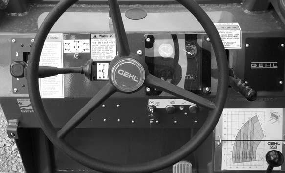
03STEERSELECTORL63618L63618
04F-N-RCONTROLL68295L68295
05IGNITION/HORN(w/oPushbuttonStart)L68052L68052
05IGNITION/HORN(PerkinsEngineonly)L63692L63692
05IGNITION/HORN(w/PushbuttonStart)L68513L68513
06MADEINUSA094951094951
07WARNING-PARKBRAKEL65925L65925
08WARNING-OPERATORL63690L63690
09WARNINGCARRYLOADLOW093475093475
10LOADCHART-ROTATINGCARRIAGEL63437---
10LOADCHART-TRUSSBOOML63454---
10LOADCHART-STANDARDCARRIAGEL63661---
10LOADCHART-BUCKETL63926---
REF.DESCRIPTION552553
NO.
01DANGER-PERSONNELL65928L65928
02WARNING-TRUSSBOOML66042L66042
03WARNING-MACHINELEVELL65930L65930
04MAINTENANCECHARTL63542L63542
05TILT/LEVELCONTROLL63632L63632
06BOOMCONTROLL63631L63631
07FILTERCHARTL68084L68084
08DANGER-PANELINPLACEL65948L65948

09DANGER-POWERLINESL65929L65929
10BRAKEFLUIDLEVELL63474L63474
11OPERATORMANUALINSIDEL65922L65922
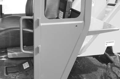
12WARNING-PINCHPOINTL65927L65927
13LOADCHART-STANDARDCARRIAGE---L68671
13LOADCHART-ROTATINGCARRIAGE---L68672
13LOADCHART-TRUSSBOOM---L68673
13LOADCHART-BUCKET---L68674
13LOADCHART-WINCH---L68675