2 minute read
SAFETY


Indicators And Controls

Caution
Become familiar with and know how to use ALLsafety devices and controls on the Telescopic Handler BEFORE operating it. Know how to stop the machine operation BEFORE operating it. This GEHLmachine is designed and intended to be used ONLYwith a GEHLCompany attachment tool, or a GEHL Company approved accessory or referral attachment tool. The GEHLCompany cannot be responsible for operator safety if the machine is used with an unapproved attachment tool.
Guards And Shields
Whenever possible and without affecting machine operation, guards and shields are used to protect potentially hazardous areas. In many places, decals are also provided to warn of potential dangers and to display special operating procedures.
Warning
Read and thoroughly understand all safety decals on the Telescopic Forklift BEFORE operating it. DO NOT operate the machine unless all factory-installed guards and shields are properly secured in place.
Dash Area
Start Keyswitch & Pushbutton
Keyswitch OFF: When the key is vertical in the keyswitch, power from the battery is disconnected to the control and instrument panel electrical circuits. Also, this is the only position in which the key can be inserted or removed.
Keyswitch ON: When the key is turned one position clockwise from the vertical (OFF) position, power from the battery is supplied to all control and instrument panel electrical circuits.
NOTE: If the engine requires repeated attempts to start, the key MUST be returned to the OFF position between starting attempts to prevent battery run down.
Start Pushbutton: With keyswitch in ON position, depress the button to activate the starter. Release it as soon as the engine starts.
Circuit Breaker: The 15 amp breaker protects dash and engine electrical circuits. If it is not in the depressed position, the gauges and indicators on the dash will not work and the engine will shut off.
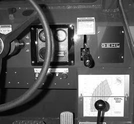
Horn Push Button: With the keyswitch ON, depress the horn button to activate horn.
Park Brake On: Abuzzer located behind the dash sounds as long as the park brake lever is engaged, and the transmission is in forward or reverse.
Transmission Oil Temperature: This lamp indicates whether the transmission oil is at the proper operating temperature. During normal operation this lamp should be off, indicating that the transmission oil system is at the proper temperature.
IMPORTANT: If this lamp comes ON during normal operation, a problem may exist in the transmission oil system. Stop the machine immediately and investigate the cause of the problem.
AlternatorLamp: Indicates the condition of the electrical charging system. During normal operation, this lamp should be off. If the charge rate is too high or too low, this lamp will come on.
Brake Failure Lamp: The front and rear brakes are on independent brake line systems. If during normal operation with the brake pedal depressed, a loss of pressure occurs in either system, the brake failure lamp will come on.
Failure in one line of the system does not affect the operation of the other system line. However, the MANDATORYSAFETYSHUTDOWN PROCEDURE should be followed and required repairs made immediately.
During normal operation the lamp should remain off.
Engine Oil Pressure Lamp: Indicates whether sufficient engine libricating oil pressure is present or not. During normal operation, with the engine running, this lamp should be off. During starting and when the engine is not running with key in the on position, this lamp will be on.
IMPORTANT: If this lamp comes ON during normal operation with the engine running, STOP the engine immediately. After allowing the oil to drain down for a few minutes, check the engine oil level. Maintain oil level at the FULLmark on the dipstick.
Hourmeter: Indicates the operating time of the machine and should be used for keeping up the maintenance log.
Coolant Temperature Gauge: Indicates the temperature of the engine coolant. Under normal conditions, this gauge should indicate approximately 185°F (85°C).
Fuel Level Gauge: Indicates the amount of fuel remaining in the fuel tank.
Load Charts: Aseries of flip charts show lift height and reach limits relative to the load weight being handled with various attachment tools.
Hydraulic Pressure Test Port: Atest gauge can be inserted to check main and steering system pressures, and joystick pressure on later units.