7 minute read
Right Instrument Panel

The instrument panel contains the following switches and indicators. Symbols on the panel represent various functions and conditions, and are visible only when indicator lamps are on.
1. Fuel Level Gauge – Displays the amount of fuel in the tank.
2. Engine Coolant Temperature Gauge –Indicates the engine coolant temperature. Note: Items 3 through 8 are indicator lamps which display the following:
3. Engine Coolant Temperature – Lights if the engine coolant becomes too hot, warning the operator to stop the engine. Allow the engine to cool, determine the cause for the high temperature and correct the problem before restarting the engine. During normal operation this indicator should be OFF.
4. Hydraulic Oil Temperature – Lights if the hydraulic oil becomes too hot, warning the operator to stop engine. Allow the hydraulic system to cool and determine the cause of the high temperature. During normal operation this indicator should be OFF.
5. Fasten Seatbelt – A momentary visual (and audible) indicator to remind the operator to fasten the seatbelt.
6. Engine Oil Pressure – Lights if the engine oil pressure drops too low, warning the operator to immediately stop the engine and determine the cause for the pressure drop. During normal operation this indicator should be OFF.
7. Battery – Lights if the charging voltage is too high or too low. During normal operation this indicator should be OFF.
8. Preheat Indicator Lamp – Lights when the preheat switch is pressed. During normal operation this indicator should be OFF.
Left Instrument Panel
1. Hourmeter – Displays the total operating hours on the loader.
2. Light Switch – Controls all the lights on the loader. Symbols denote the four positions of the light switch. In a clockwise direction these are:
•OFF
•Tail lights ON
•Front work lights with tail lights ON
•both front and rear work lights
For the lights to function, the keyswitch must be in the RUN position.
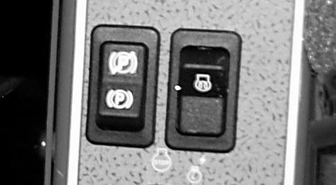
3. Parking Brake Switch – Used to manually apply the parking brake. The red indicator on the switch lights when the parking brake is applied.
4. Keyswitch – In a clockwise rotation, these positions are:
OFF Position – With the key vertical, power from the battery is disconnected to the controls and instrument panel electrical circuits. This is the only position the key can be inserted or removed from the keyswitch.
ON (or Run) Position – With the key turned one position clockwise from vertical, power from the battery is supplied to all control and instrument panel electrical circuits.
START Position – With the key turned fully clockwise, the electric starter energizes, to start the engine. Release the key to the RUN position after the engine starts.
Note: The engine cannot be started unless the operator is sitting in the seat, the restraint bar is lowered, and the auxiliary hydraulic control is in “neutral.”
5. Accessory Outlet – 12-volt DC power outlet.
6. Preheat Switch – Use to preheat the engine for starting in cold conditions.
T-Bar Controls
The loader is equipped with T-Bar controls. The left T-Bar controls the drive, and the right T-Bar controls the lift/tilt.
Drive Controls
Forward, reverse, speed and turning maneuvers are controlled by movement of the left T-Bar. To go forward, push the control forward; for reverse, pull the control rearward. To turn right, twist the control clockwise; to turn left, twist the control counterclockwise. For gradual turns, twist the T-Bar slightly clockwise or counterclockwise. For sharp turns, twist the control fully clockwise or counterclockwise.
Figure10 T-Bar Controls
Moving the T-Bar farther from neutral increases the speed steadily to the maximum travel speed. Tractive effort decreases as speed increases. For maximum tractive effort, move the T-Bar only slightly from the neutral position. The engine will stall if the control is moved too far forward when loading the bucket.
Be sure the controls are in neutral before starting the engine. Operate the controls gradually and smoothly. Excessive speed and quick control movements without regard for conditions and circumstances are hazardous and could cause an accident.
Lift/Tilt Control
Moving the lift arm and tilting the attachment are accomplished by movement of the right T-Bar. To raise the lift arm, pull the control straight rearward; to lower the lift arm, push the control straight forward. To tilt the attachment downward, twist the control clockwise; to tilt the attachment up or back, twist the control counterclockwise.
Note: The speed of the lift/tilt motion is directly proportional to the amount of T-Bar movement and engine speed.
To place the lift arm into the detent (“float”) position, push the right T-Bar all the way forward into the detent. This position allows the lowered lift arm to “float” while traveling over changing ground conditions.
Never push the lift/tilt T-Bar control into the float position with the attachment loaded or raised, because this will cause the lift arm to lower rapidly.
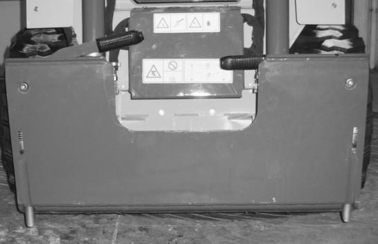
Auxiliary Hydraulic System
Auxiliary hydraulics are used with an attachment that has a mechanism requiring hydraulic power of its own.
Important: Always be sure the auxiliary hydraulic control is in neutral before starting the loader or removing the auxiliary hydraulic couplers.
A foot pedal is used to control the direction of oil flow.
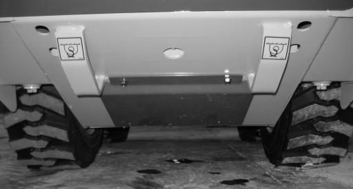
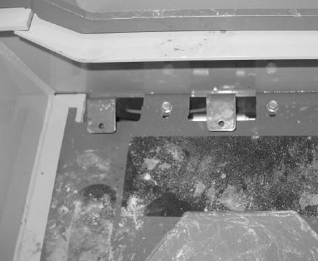
Attachment Mounting
The loader is equipped with a two-pin AllTach® attachment bracket for mounting a bucket or other attachment. Two latch levers secure the attachment. Rotate the levers downward until they are horizontal to engage the latch pins. Rotate the levers upward until they are vertical to disengage the latch pins.

To prevent unexpected attachment release from the hitch, be sure to secure the lock pins by rotating the levers downward into a horizontal position and verifying that the pins are properly engaged.

Warning
Warning
Before starting the engine and operating the loader, review and comply with all safety recommendations in the Safety chapter of this manual. Know how to stop the loader before starting it. Also, be sure to fasten and properly adjust the seatbelt and lower the operator restraint bar.
Before Starting the Engine
Before starting the engine and running the loader, refer to the Controls and Safety Equipment chapter and familiarize yourself with the various operating controls, indicators and safety devices on the loader.
Starting the Engine
The following procedure is recommended for starting the engine:
1.Carefully step up onto the back of the bucket or attachment and grasp the ROPS handholds to get into the operator’s compartment.
2.Fasten the seatbelt and lower the restraint bar.
3.Verify the following:
the lift/tilt, drive and auxiliary controls are in their neutral positions,
the parking brake is on.
4.Push the throttle forward to half speed.
Note: When the key is turned to the RUN position, an indicator will light on the instrument panel and a buzzer will sound momentarily to remind you to check that your seatbelt is fastened.
5.Turn the keyswitch to the START position.
Important: Do not engage the starter for longer than 15 seconds at a time. Longer use can overheat and damage the starter. Allow the starter to cool for 20seconds between uses.
After the engine starts, allow a sufficient warm-up time before attempting to operate the controls.
Important: If the warning lights do not go off, stop the engine and investigate the cause.
Cold Starting Procedure
Do not use starting fluid (ether) with preheat systems. An explosion can result, which can cause engine damage, injury or death.
Also see Starting the Engine (page27). Turn the key switch to the “RUN” position.
Push the “Preheat” button (Figure14) on the instrument panel to preheat the engine for a maximum of 30 seconds.
If the temperature is below 32°F (0°C) try the following to make starting the engine easier:
•Replace the engine oil with 5W30.
•Make sure the battery is fully charge.
•Install block or tank heater on the engine. Let the engine run for a minimum of 5 minutes to warm the engine and hydraulic fluid before operating the loader.
Stopping the Loader
The following procedure is the recommended sequence for stopping the loader:
1.Check that the drive control handle(s) is (are) in “neutral” position.
2.Lower the lift arm and rest the attachment on the ground.
3.Pull back the throttle lever to the low idle position (and remove foot from the accelerator pedal).
4.Turn the keyswitch to the OFF position to shut off the engine.
5.Move the lift/tilt control to verify that the safety interlock system is preventing movement.
6.Raise the restraint bar, unfasten the seatbelt and grasp the hand holds while climbing out of the operator’s compartment.
Note: The skid-steer loader is equipped with a spring-applied automatic parking brake. The parking brake is engaged when the operator lifts the restraint bar, leaves the operator’s seat or shuts off the engine, or when the brake switch is applied.
Parking the Loader
Park the loader on level ground away from traffic. If this is not possible, park the loader across the incline and block the tires to prevent movement.
Jump Starting the Engine
If the battery becomes discharged or does not have enough power to start the engine, use jumper cables and the following procedure to jump-start the loader engine.
Warning
The ONLY safe method for jump starting with a discharged battery is for TWO PEOPLE to perform the following procedure. The second person removes the jumper cables so that the operator does not have to leave the operator’s compartment with the engine running. NEVER make jumper cable connections directly to the starter solenoid of either engine. DO NOT start the engine from any position other than on the operator’s seat and then ONLY after being sure ALL controls are in “neutral”.
Closely follow the procedure, in order, to avoid personal injury. In addition, wear safety glasses to protect your eyes and avoid leaning over the batteries while jump-starting.
DO NOT jump-start the battery if it is frozen, because it may rupture or explode. Note: BE SURE the jumper battery is a 12-volt D.C. battery.
1.Turn the keyswitches of both vehicles to OFF, be sure the vehicles are in “neutral” and NOT touching each other.
2.Connect the positive (+) jumper cable to the positive (+) battery terminal on the disabled loader first. DO NOT allow the positive clamps to touch any metal other than the positive (+) battery terminals or the positive jump stud (if equipped.)
3.Connect the other end of the positive jumper cable to the jumper vehicle’s battery positive (+) terminal.
4.Connect the negative (-) jumper cable to the jumper vehicle’s battery negative (-) terminal.
5.Make the final negative (-) jumper cable connection to the disabled loader’s engine block or loader frame (ground) – NOT to the disabled battery’s negative post. If connected to the engine, keep the jumper clamp away from the battery, fuel lines and moving parts or the negative jump stud (if equipped.)
6.Start the loader. If it does not start at once, start the jumper vehicle engine to avoid excessive drain on the booster battery.
7.After the disabled loader is started and running smoothly, have the second person remove the jumper cables (negative (-) jumper cable first) from the jumper vehicle’s battery and then from the disabled loader while being sure NOT to short the two cables together. Allow sufficient time for the skid-steer loader alternator to build-up a charge in the battery before attempting to operate the loader or shut the engine off.