1 minute read
Product and Component Plate Locations

Product and Component Plates
1.Operator protective system plate: with, e.g., model, certification and operator protective system serial number
2.Product plate: with Product Identification Number and, e.g., model/type designation
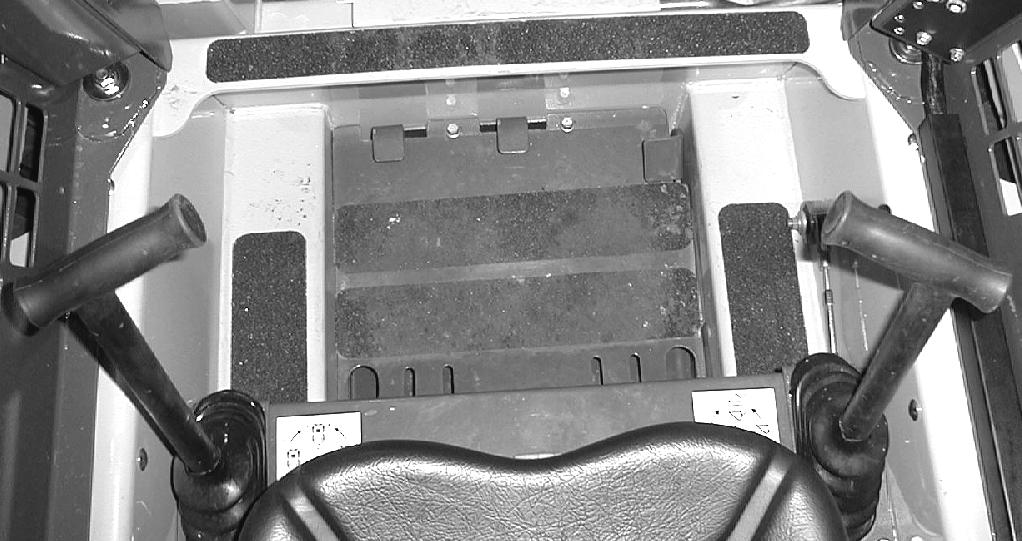
3.Component plate transmission: with, e.g., product and serial numbers
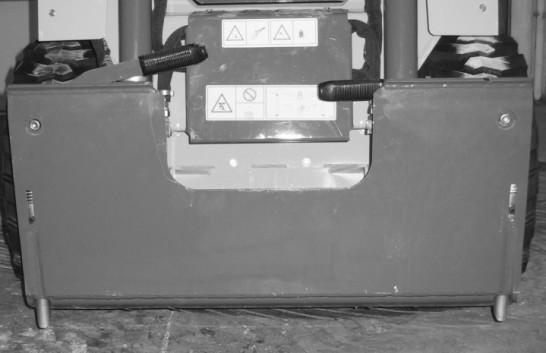
4.Component plate rear drive axle: with, e.g., product and serial numbers
5.Engine plate: with, e.g., type designation, product and serial numbers
6.Seat plate according to ISO 7096
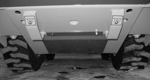
7.Component plate front drive axle: with, e.g., product and serial number
Direct and/or Indirect Visibility
Tested in accordance with ISO 5006: 2017.
The machine has been subjected to a static visibility assessment with the lift structure in a carry position or 200 mm (7-7/8 in.) above the ground. The test simulates operator visibility from the operator’s position:
• The line of sight between the operator’s eye position and a point on the ground at a 12 m (472 in.) radius.
• On a rectangular boundary 1 m (39 in.) from the machine, 12 m (47 in.) above the ground.
• Masking was recorded as shown (Fig. 6), and is within the allowable limits in accordance with ISO 5006: 2017.
• The standard/test does not account for head movement or rotation, which can improve visibility and mitigate masking.
This diagram indicates the blind spot zone on the visibility test circle (radius = 12 m [47 ft.]) and the 1 m (39in.) rectangular zone around the machine.