11 minute read
SAFETY SIGNS

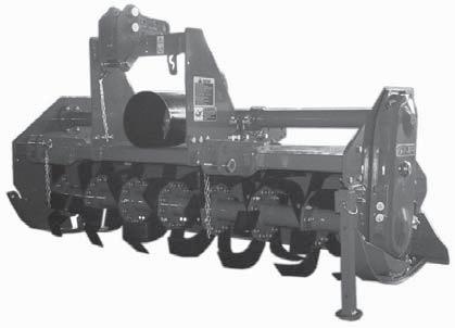
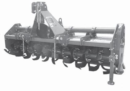
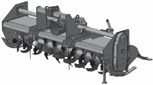
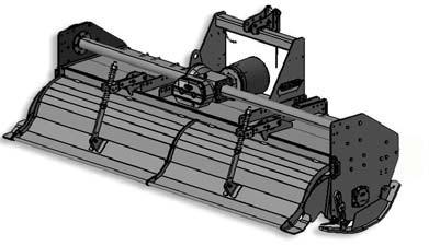
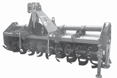
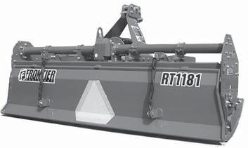
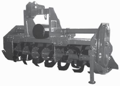
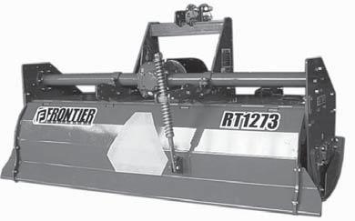
from Frontier Rotary Tillers RT 1173 RT 1273 RT 2293 RT 1181 RT 2283 Operator's Manual(F07011069) - PDF

Safety-alert symbol
Read and recognize safety information.
Be alert to the potential for personal injury when you see this safety-alert symbol.
On your machine safety labels, the words DANGER, WARNING, and CAUTION are used with safety-alert symbol.
DANGER identifies the most serious hazards. In this manual, the word CAUTION and this symbol call attention to safety messages.
Identification machine
Identification plate machine
Machine safety labels
1) WARNING: AVOID INJURY FROM ROTATING KNIVES:
• Keep hands, feet and clothing away.
2) WARNING: AVOID INJURY FROM PTO:
• Keep all shields in place. Keep hands, feet and clothing away.
• Operate only with 540 RPM.
3) CAUTION: AVOID INJURY
• Read Operator’s Manual
• Ballast power unit per operator’s manual
• Know location and function of controls
• Keep all shields in place
• Stay clear of power driven parts
• Never carry riders
• Keep people and pets a safe distance away from machine BEFORE DISMOUNTING OR SERVICING
• Shut off engine and remove key
• Lock brake for park
• Lower or block up machine
4) DANGER: ROTATING DRIVELINE - CONTACT CAN CAUSE DEATH - KEEP AWAY! - DO NOT OPERATE WITHOUT:
• All driveline, tractor and equipment shields in place
• Drivelines securely attached at both ends
• Drivelines shields that turn freely on driveline.
5) DANGER: SHIELD MISSING DO NOT OPERATE
Picture Note: Separate telescoping driveshaft members to locate safety label. Label attached to outer profile tube.
Safety Signs - Page 7
Machine Safety Labels And Positions
Machine Safety Labels And Positions


Preparing The Vehicle
Preparing the tractor
CAUTION: Avoid injury. Proper ballastings is required for safe operation of your tiller
IMPORTANT: Refer to the tractor operator manual for proper ballasting information and tire inflation
• A 540 rpm PTO
• Refer to the tractor operator manual for correct ballasting and tire pressure, depending on installed equipment.
Park vehicle safety
• Stop vehicle on a lever surface, not on a slope.
• Disengage PTO.
• Engage the park brake.
• STOP the engine.
• Remove the key.
• Before you leave the operator’s seat, wait for engine and all moving parts to STOP.
Stay clear of rotating drivelines
Entanglement in rotating driveline can cause serious injury or death:
• Wear close fitting clothing.
• STOP the engine and be sure PTO driveline is stopped before getting near it.
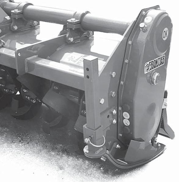
Installing tiller on tactor
1. Back tractor into position and align draft links (A) with draft link brackets on tiller using tractor rockshaft control.
CAUTION: Before you work around hitch:
• STOP engine.
• LOCK park brake.
• FIRMLY block tiller on horizontal surface .
Locate driller pin in holes (B).
RT 1173 - 1181 model:
2. Insert bushings (D) in each draft links than fasten each draft link to draft link brackets with drilled pins and quiklock pins (C).
For cat. «II» Standard bushings Ø = 28 (inch 1.102)
For cat. «II» Quick Coupler bushings Ø = 36,5 (inch 1.437)
For cat. «I» iMatch Quick Hitch Ø = 36,5 (inch 1.437)
Locate driller pin in top lift brackets holes (B).
RT 1273 model (Cat. «II» Std.):
2. Fasten each draft link (A) to draft link brackets with drilled pins and quiklock pins (C).
Locate driller pin in lower lift brackets holes (E).
RT 1273 model (Cat. «II» Quick Coupler):
2. Insert bushings (D) in each draft links (A) than fasten each draft link to draft link brackets with drilled pins and quiklock pins (C).
Locate driller pin in holes (B).
RT 2283-2293 model (Cat. «II» Std.):
2. Fasten each draft link (A) to draft link brackets with drilled pins and quiklock pins (C).
RT 2283-2293 model (Cat. «II» Quick Coupler):
2. Insert bushings (D) in each draft links (A) than fasten each draft link to draft link brackets with drilled pins and quiklock pins (C).
Locate driller pin in top holes (D)
RT 1273-2283-2293 model (Cat. «II» Std.):
3. Install center link (F) on tiller and fasten with drilled pin and quiklock pin (E).
Locate driller pin in top holes (G)
RT 1273-2283-2293 model (Cat. «II» Quick Coupler):
3. Install center link (F) on tiller and fasten with drilled pin and quiklock pin (E).
4. Install PTO shaft to tractor.
IMPORTANT: Tiller MUST BE level front to rear.
• Engage the cardan shaft and check that it is perfectly locked on the tractor PTO (G). Check that the guard (H) is free to turn and fix it with the relative latch.
5. Raise tiller.
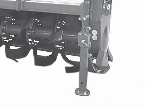
6. Remove spring locking pin (K) from parking stand.
7. Slide parking stand (I) and way up on tiller bracket (J).
8. Fasten with spring locking pin (K).
9. Level tiller (See Leveling Tiller in the Operating Tiller section).
10. Adjust sway chains on tractor lower draft arms to minimize side way.
PTO shaft
The PTO shaft, supplied with the machine, is of standard length.
Therefore it might be necessary to adapt the PTO shaft. In that case, before doing anything, consult the Manufacturer for the eventual adaptation.
When the PTO shaft is fully extended, the two tubes must overlap by at least 6 inch (A). When fully inserted, the minimum play must be 1,6 inch (B).
CAUTION: If the implement is used on another tractor, always check that the guards completely cover the rotating parts of the PTO shaft.
Installing - Page 12
PTO shaft with clutch
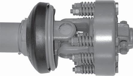
The PTO shaft can be equipped with safety clutch to protect the transmission components of the machine from stress and/or excessive overloads.
The tilt of the PTO shaft must not exceed 10 degrees.
The clutch is already pre-adjusted for average stress. If it slips too easily (and overheats), it will be necessary to evenly tighten all the nuts (D) that retain the springs. The clutch disks must be changed if the clutch still slips after all the nuts have been tightened. If the clutch does not slip, evenly unscrew all the spring fixing nuts (D). Unscrew one turn at a time and check the clutch after having worked about 300 meters. Repeat the operation if necessary, remembering to unscrew one turn at a time. If the clutch maintains a temperature of about 40-50 (104-122 °F) degrees during work, this means that it has been correctly regulated.
IMPORTANT: Never fully tighten the nuts. This would void the function of the springs and, subsequently, of the clutch, thus damaging the transmission components.
NOTE: This inspection must be performed at the beginning of each new season.
Installing - Page 13
Quick Coupler (optional)
1) Install hitch Quick Coupler (A) on the tractor (see tractor operator manual).
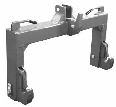
2) Stop vehicle on a level surface, not on a slope, then moving back to the tractor until the Quick Coupler (A) is range with the (B) and (C) hitch points.
3) Raise the Quick Coupler (A) and make sure that tiller’s hitch is in the right position (E).
CAUTION: Before you work around hitch:
• STOP engine.
• LOCK park brake.
• FIRMLY block tiller on horizontal surface .
Park vehicle safely
• Stop vehicle on a level surface, not on a slope.
• Disengage PTO.
• Engage the park brake.
• STOP the engine.
• Remove the key.
• Before you leave the operator’s seat, wait for engine and all moving parts to STOP.
Stay clear of rotating drivelines
Entanglement in rotating driveline can cause serious injury or death:
• Wear close fitting clothing.
• STOP the engine and be sure PTO driveline is stopped before getting near it.
Installing - Page 14
Removing tiller
1. Raise tiller.
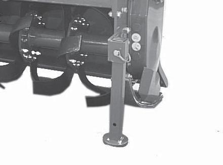
2. Put parking stand (A) in the DOWN position: Install spring locking pin (C) in order to secure parking stand (A) to the tiller bracket (B).
3. Lower tiller to the ground.
CAUTION: Before you work around hitch:
• STOP engine.
• LOCK park brake.
• FIRMLY block tiller on horizontal surface .
4. Disconnect driveline from tractor by pulling back on coupler to release it from the LOCKED position.
5. Remove quik-lock pin (D) and drilled pin (E) from center link (F).
NOTE: Put quik-lock pins and driller pins back into brackets on tiller for storage.
6. Remove draft links (G) from draft link brackets (H) by removing quiklock pins (I) and drilled pins (L).
NOTE: Put quik-lock pins and driller pins back into brackets on tiller for storage.
7. Drive tractor forward slowly.
Removing tiller with Quick Coupler
1. Raise tiller.
2. Put parking stand (A) in the DOWN position: Install spring locking pin (C) in order to secure parking stand (A) to the tiller bracket (B).
3. Lower tiller to the ground.
4. Raise the two Quick Coupler levers (D) to unloch tiller (Quick Coupler figure, page 14).
5. Lower Quick Coupler till further free the tiller.
Operate safely
• Protect your hands when you inspect or unplug the tiller. You may need gloves or tools, such as a screwdriver or scraper. Be sure hardware is tight. Repair or replace damaged, badly worn, or missing parts. Be sure guards and shields are in good condition and fastened in place. Make any necessary adjustments before you operate.
• Clear work area of objects that you do not want tilled into the ground or that might damage the tiller. Consider the tilling area and set up a safe tilling pattern. Do not till under condition in which traction or stability is doubtful. Keep people and pets out of the work area. Stop machine if anyone enters the area.
• If you hit an object, stop the machine and inspect it. Make repairs before you operate. Keep machine properly maintained and in good working order.
• DO NOT leave machine unattended when it is running.
• Only operate during daylight or with good artificial light.
• DO NOT let anyone, ESPECIALLY CHILDREN, ride on machine or vehicle. Riders are subject to injury such as being thrown off. Riders may also obstruct the operator’s view, resulting in the machine being operated in an unsafe manner.
• DO NOT let children or an untrained person operate machine.
• DO NOT wear radio or music headphones while operating the machine. Safe operation requires your full attention.
• DO NOT operate the tractor and tiller when you are tired or ill.
Operating
Wear appropriate clothing
• Wear close fitting clothing and safely equipment appropriate for the job.
• Loud noise can cause impairment or loss of hearing, wear a suitable protective device such as earplugs.
Stay clear of rotating drivelines
Entanglement in rotating driveline can cause serious injury or death:
• Wear close fitting clothing
• Stop the engine and be sure PTO drivelines is stopped before getting near it.
CAUTION: Before you work around hitch:
• STOP engine.
• LOCK park brake.
• FIRMLY block tiller on horizontal surface .
Raising parking stand
1. Remove spring locking pin (C).
2. Slide parking stand (A) and way up on tiller bracket (B).
3. Fasten with spring locking pin (C).
Lowering parking stand
1. Remove spring locking pin (C).
2. Slide parking stand (A) and put down on tiller bracket (B).
3. Install spring locking pin in order to secure parking stand to the tiller bracket.
4. Fasten with spring locking pin (C).
Leveling attachments (side-to-side)
1. Start the engine. Raise the tiller.
2. Stop the engine. Lock the park brake.
CAUTION: DO NOT work under a raised tiller unless it is safely supported.
Operating - Page 17
Leveling tiller (front-to-rear)
1. Start the engine.
2. Lower the tiller to 25 mm (1 in.) off the ground.
3. Stop the engine.
4. Make sure the top of the tiller is LEVEL, or PARALLEL with the ground, front-to-rear.
5. Adjust level, if necessary. To adjust level: a. Start the engine. b. Lower the tiller to the ground. c. Stop the engine. d. Loosen jam nut (A). e. Tighten jam nut.
• Shorten the center link (B) to lower the front of the tiller.
• Lengthen the center link (B) to raise the front of the tiller.
CAUTION: Before you work around hitch:
• STOP engine.
• LOCK park brake.
• FIRMLY block tiller on horizontal surface .
Adjusting skid shoes
Before adjusting skid shoes lift tiller, place tiller on top of two wooden blocks underneath tiller rotor (see figure).
1. Raise tiller.
2. Place wooden blocks.
3. Lower tiller on wooden blocks.
4. Loosen pivot bolt (A) and (D).
5. Loosen adjusting bolt (B) and lock nut.
6. Adjust skid shoe (C) to desired position.
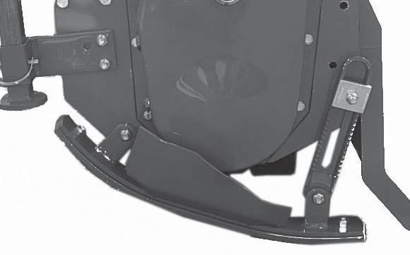
7. Tighten bolts (A), (B) and (D).
NOTE: Adjust both skid shoes to same depth.
6. Repeat above steps for the other skid shoe. Adjusting roller RT 2283-2293 model
Mechanical version: to adjust working depth, act on the cranks of the side mechanical hand jacks. (A)
Hydraulic version: to adjust working depth, act on the hydraulic distributor of the tractor, connected to the hydraulic jacks. (B)
Operating - Page 18
Adjusting leveling board
2. Lower leveling board to top of ground (C):
• Tilled soil (D) will be fine and level.
• Tractor speed will determine size of clods (E).
3. Raise leveling board (C):
• Tilled soil (D) will be coarse and rough.
• Tractor speed will determine size of clods (E).
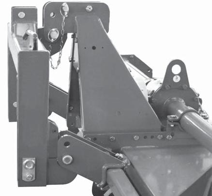
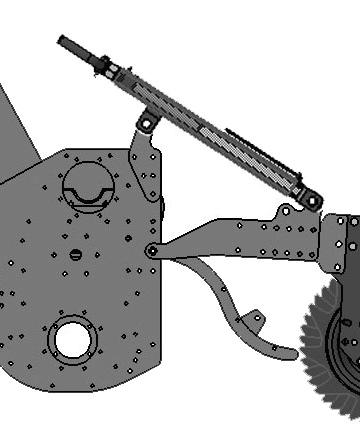
Spring Ram (1)
Besides supporting the levelling plate and acting as a shock absorber for it during road transport, the spring ram (1) prevents the machine from overturning when parking.
To adjust the spring pre-loading, screw or unscrew the upper nut (2) using the spring adjuster.
The effect of the levelling plate on the soil can be increased or decreased depending on the position, established by the position of the nut (3) in the two holes of the ram (4).
CAUTION: Before you work around hitch:
• STOP engine.
• LOCK park brake.
• FIRMLY block tiller on horizontal surface .
Change speed
Rotary harrows are equipped with a gearshift with one pair of gears. A variety of rotation speeds of the rotor can be obtained so that the needs of the operator can be better met. It is very useful for land which is uneven in that it makes rotary hoeing easy and at the same time allows the tractor to be maintained at a constant speed.
To change tiller speed you must:
1) Unscrew its bolds and remove the rear cover of the gearbox.
CAUTION: Watch out: oil will come out.
2) It is advisable to bend the rotary cultivator forwards.
3) Pull the gears off their shafts and invert the position of their seats.
The name-plate on the cover gives the number of teeth of the gear pair originally installed by the Manufacturer, furthermore, as on page 4 of this handbook, there are the speeds pertainig to the pairs of gears monuted on purchase, plus of the spare pairs.
Each rotary cultivator with gear change has a label which indicates the gear couple mounted as first equipment. The label is attached to the third-point.
Operating - Page 19
CAUTION: Be very careful and ensure to use the right gears, since some gear pairs cannot be inverted, and gears from different pairs cannot be interchanged. Strictly comply whith the pairs of gears indicated, in the chart on page 4.
Optimum tilling depends on two factors:
1) Forward speed of the tractor.
2) Rotation speed of the blade-carrying rotor. The faster the rotor rotates, the more chopped up the soil will be.
Tilling tips
Before You till:
• Pick up rocks and foreign objects.
• Mow tall weeds and grass to keep them from wrapping around tines or tine shaft.
• Check tines. Loose, bent, broken, or missing tines reduce operating efficiency. If necessary, replace tines.
Test the soil by squeezing it in your hand. If soil forms a ball, it is too wet to till. If soil does not compress easily or falls apart, it is ready to till.
DO NOT till when soil is wet. Wet soil will stick to the tines and tine shaft. Wet soil will also dry out and become hard, making it hard to work with during the growing season.
During tilling
CAUTION: Never lower tiller into the ground while the tractor is turning
• DO NOT back up or make sharp turn with tiller in ground.
• Move PTO switch lever to ON when tiller is out of the ground. Move tractor forward and lower tiller into the ground.
• When you till hard ground or sod, till at a shallow depth on first pass. Increase depth on each pass.
• When tilling on a hillside:
- Work up the the slope, if possible.
- If lateral work cannot be avoided, work from the top to the bottom in order to limit any terracing effect.
Replacement parts
See Service Dealer for original parts.
PART NUMBERS MAY CHANGE, use part numbers listed at the end of this manual when you order. If a number changes, your dealer will have the latest number.
WHEN YOU ORDER PARTS, your Frontier Equipment dealer needs your machine serial number. This is the number you have recorded in the INTRODUCTION section in the front of this manual.

