18 minute read
Service and Maintenance Safety

from Frontier Offset Agricultural Disks DH5210-DH5212-DH5214-DH5216 DH5217-DH5219-DH5221 Operator's Manua

□ Before servicing the disk, always:
1. Lower the disk to the ground.
2. Shut the tractor engine off.
3. Engage the tractors parking brake and/or place transmission in park.
4. Relieve the hydraulics by moving the control lever back and forth.
5. Remove the ignition key.
□ Never work under a raised disk. The disk could fall suddenly causing serious personal injury. Never rely on the hydraulic system to hold the disk up.
□ Periodically visually inspect the entire disk. Hydraulic fluid leaks and broken, missing or faulty parts can create a hazard. Make necessary repairs.
□ Use caution when inflating tires. Use a clipon air chuck, extension hose with gauge, and stand to one side away from the tire when inflating to avoid the possibility of personal injury due to blow offs, etc. Maintain proper air pressure in the tires. Never exceed the manufacturer’s maximum pressure displayed on the sidewall of the tire.
□ Before disconnecting any hydraulic line relieve the pressure. Escaping hydraulic oil under pressure can have sufficient force to penetrate the skin causing serious personal injury. If injured by escaping hydraulic fluid, obtain medical treatment immediately.
□ Handle the gang assemblies with care. The disk blades are sharp and can cut or slice skin. Use chock blocks to prevent the gang assemblies from rolling during servicing. Wear gloves when handling the disk blades or gang assemblies.
□ After working on the hydraulic cylinder or any other components of the hydraulic system, carefully cycle the hydraulic cylinder several times to purge air from the system and check all components for leaks. Always be sure the hydraulic lines are free of air and do not leak. ORB fittings may not leak even though they are only finger tight – tighten with a wrench. Check hydraulic hoses for cuts or abrasions and replace if necessary.
□ Securely support any machine elements that must be raised for service work. Use suitable lifting devices and support stands where required. If using chains or straps make sure they are of sufficient strength for the load and are in good repair.
□ To avoid injury wear gloves, steeltoe boots, safety glasses, hearing protection, safety helmet and other safety equipment where warranted.
□ Understand the service procedure before doing the required work. Keep the work area clean and dry.
Lubricate the Disk
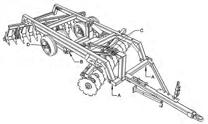
□ The following illustrations highlight those areas of the disk subject to stress and wear. Unless indicated otherwise, these fittings should be greased daily or after every 10 hours of operation.
□ Use a pressure lubrication gun and apply a sufficient amount of No. 2 multipurpose lithium grease or equivalent to flush out the old grease. Wipe the grease fitting clean before greasing.
□ Grease all fittings before first use of the season and before storage at the end of the season.
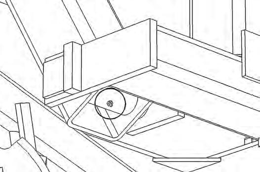
□ Grease wheel bearings (D) sparingly – 6 ‘shots’ every 100 hrs. D A B C
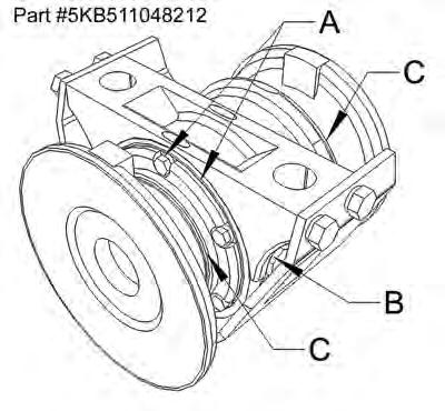
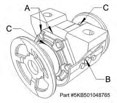
Check the Oil-Bath Bearings
Visually check the oil-bath bearings daily. Oil-bath bearing assemblies can leak oil from three locations and attention should be paid to these areas. A - Oil can seep from between the bearing housing and the end cap or from around the bolts that hold the end cap to the housing. This condition is caused by loose bolts or damaged gaskets. Gaskets are placed between the end cap and the housing to preload the taper bearings in the housing. The solution is to tighten the bolts (30 ft/lbs) or replace the gaskets. B – Oil can seep past the check plugs. Plugs may use a pipe thread. Remove, clean the threads, apply “pipe dope” or Teflon tape and reinstall. C – Oil may seep by the metallic duo-cone seals. This may be caused by worn seals, loose gang axles or extreme temperature fluctuations. Worn seals should be replaced immediately to prevent catastrophic bearing failure. Such a failure will ruin all the other components of the bearing. Loose gang axles can allow the bearing flanges to move outwards and thereby allow the seals to separate. Be sure to keep gang axles tight. Because the seals are made of metal, they can expand and contract with extreme temperature fluctuations. When they contract the sealing surfaces separate and small amounts of oil can escape. This will normally occur when the disk is in storage. Putting the disk to use will normally allow the seals to re-seat themselves. Check the oil and add 90W gear oil if necessary.
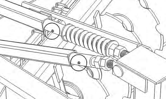
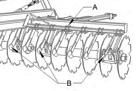
Adjusting the Scrapers
Adjust the scrapers as close to the disk blades as possible without touching the blades. To move a scraper, first loosen the u-bolts (A) holding it to the scraper bar. Use a hammer to alternatively tap the top side of the u-bolts and the scraper itself in the required direction. Once in position tighten the u-bolts equally. Turn the blades occasionally while tightening the u-bolts to ensure the scraper is not contacting the disk blade.
In some conditions (e.g. heavy trash or virgin ground) plugging can occur at the bearings. Removing the scrapers (B) at these locations can alleviate the problem.
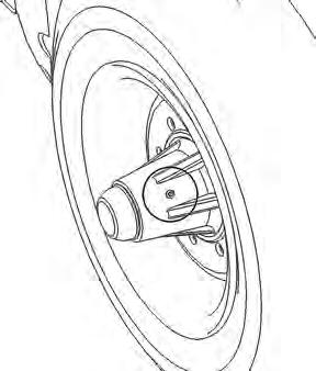
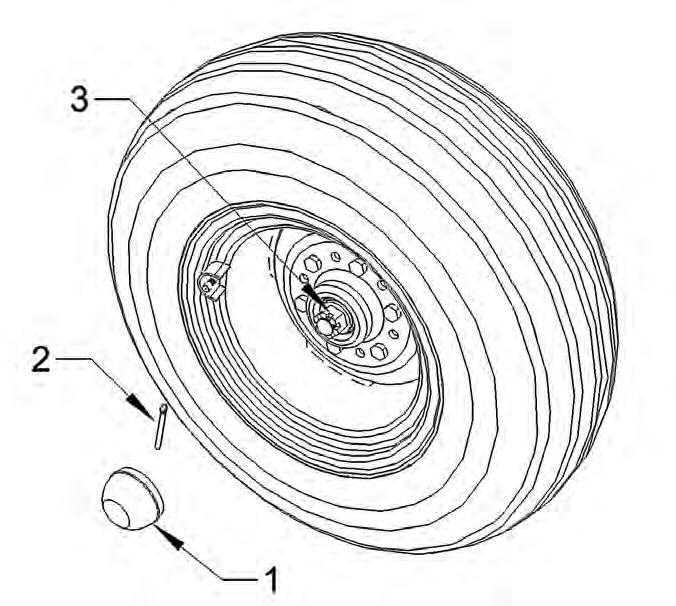
Repack and Pre-Load Wheel Hub Bearings
The wheel bearing pre-load should be set periodically or more often if transported frequently. Raise the tire so it can rotate and:
1. Remove the dust cap from hub.
2. Remove cotter pin from nut and spindle.
3. While turning the tire, tighten the castellated nut until there is a slight but noticeable drag on the bearing. Do not back the nut off. Place the cotter pin in the nearest hole to secure the nut. Replace the dust cap and gasket.
Repack the wheel hub bearings yearly by:
1. Remove the tire from the hub.
2. Remove the dust cap and gasket.
3. Remove the cotter pin and remove the castellated nut from the end of the spindle.
4. Slide the hub off the spindle taking care not to damage the seal..
5. Clean bearing cones, dust cap and nut with kerosene or other appropriate solvent.
6. Clean the inside of the hub and inspect the bearing cups and the seal. If they show excessive wear or are damaged, replace both the cups and cones and seal. Though it is not always necessary, it is advisable to replace the seal whenever repacking the hubs.
7. Pack the bearing cones and inside cavity of the hub with No. 2 multi-purpose lithium grease or equivalent. Make sure no foreign material contaminates the lubricant.
8. Place the rear bearing cone into the back of the hub and press the seal into the hub. Place a light film of grease on the seal surface and carefully slide the hub onto the spindle taking care not to damage the seal.
9. Place the outside bearing cone over the spindle and into the hub.
10. Install the castellated nut and follow the procedure for setting the pre-load.
11. Reinstall the dust cap and tire.
Check the wheel lug nuts and wheel bearing pre-load after the next week of operation.
Fluid and Fastener Specifications
□ DISK GANG ASSEMBLY AXLES: The disk gang assembly axles are 15/8” in diameter (optional 2 1/8”) and are threaded at either end. A heavy cast nut is installed at either end and tightened to complete the rigid gang assembly. To insure proper functioning and maximum durability, the axle nuts should be checked and tightened daily during the first (7) seven days of operation when the disk is new or after replacing any of the gang assembly components. When installing the nut, apply an antiseize compound to the threads. Over tightening the gang axles can damage components of the gang assembly.
Recommended Torque (Ø1-5/8”) – 800-1000 ft/lbs
Recommended Torque (Ø2-1/8”) – 1000-1200 ft/lbs
□ FASTENERS: Tighten all fasteners after the first day of operation and seasonally thereafter to the following settings.
Torque
The torque values in table are for plated unlubricated bolts and nuts.
Grade 5
Grade 8
□ OILBATH BEARING OIL: The oilbath bearing contains backtoback tapered roller bearings operating in gear oil. The bearing has a check plug on the side of the housing. Oil is filled to the bottom of the check plug hole. Fill oil until it begins to run out the hole.
Recommended Gear Oil – SAE 90W (API GL-4)
A heavier weight of gear oil may be used in hot climates where there may be constant temperatures in excess of 90°F.
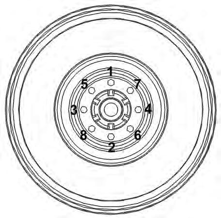
□ TIRE AND WHEEL SERVICE
When checking wheel nut for tightness or remounting the wheel, tighten the wheel bolts in the sequence illustrated.
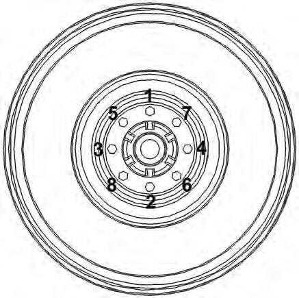
Torque wheel nuts to 100-125 ft/lbs.
Check the tires regularly for cuts or other damage.
Check and adjust tire pressure when tire is cold. Maintain tire pressure at 60 psi.
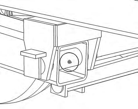
Keep Gang Assemblies Tight
□ To ensure proper function and maximum durability, the axle nuts should be checked and tig htened daily during the first (7) days of operation when the disk is new or after replacing any of the gang components.
□ Loose axles may bend or break or cause damage to other components of the gang assembly. Mai ntaining tight gangs is necessary to ensure maximum bearing life.
□ A loose gang assembly is evident when some disk blades stop turning when disking or turn at a di fferent speed than other disks on the same assembly.
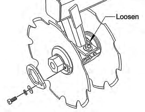
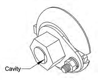
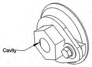
□ To tighten the axle without removing the gang assembly from the disk:
To minimize the possibility of thread damage, clean out the cavity between the inside of the nut and the flat milled surface at the end of the axle. After using compressed air or a pressure washer to remove as much material as possible, pour or spray a light oil or penetrating fluid into the cavity.
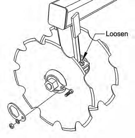
Unbolt and remove the nut locks from the end washers on both ends of the axle. Loosen but do not remove the bolts holding the bearings to the bearing standards. Place one wrench on an axle nut to prevent the axle from turning. Use the other wrench and an extension or a sledge hammer to tighten the axle nut on the opposite end of the axle. Tighten the nut on 15/8” axle to 8001000 ft/lbs and on a 21/8” axle to 10002000 ft/lbs.
Retighten the bearing bolts.
If the gang is excessively loose it may be necessary to completely disassemble the entire assembly and clean the mating surfaces between the spools, bearings, end washers and disk blades.
□ If it is necessary to remove and disassemble the gang assembly, use suitable lifting devices and supports to prevent injury.
With the disk lowered to the ground, first remove the scrapers and then unbolt the bearings from the bearing standards. There are four bolts holding each gang assembly to the gang bar. Once the bolts are removed, raise the disk high enough to either roll or pull the assembly from under the disk. Block the gang to prevent it from rolling. Remove the nut locks from both ends of the assembly. Use one wrench to keep the gang from turning while using the other wrench to tighten the nut at the opposite end of the assembly. It may not be possible to properly tighten the gang if dirt, grit or debris has builtup between the components. In this case remove a nut from one end of the axle, slide off the end washers, bearings, spools and disk blades. Thoroughly clean the mating surfaces between the components and reassemble on the disk gang (see assembly section). Clean the threads on the axle and in the axle nut. Apply an antiseize compound to the axle threads and reinstall the nut. Tighten the nut and reinstall the nut locks. Place the assembly under the disk and bolt to the gang bar bearing standards. Occasionally turn the gang while tightening the bolts to check the gang turns freely. Retighten the bearing bolts after the first 1012 hours of operation.
As sembly Safety
□ Wear proper attire when assembling disk. Always wear relatively tight and belted clothing to av oid entanglement in equipment. Wear sturdy, grip work shoes and protective equipment for eyes, hands, hearing and head.
□ Handle the disk gang components with care during assembly. The disk blades are sharp and can cut hands, feet, etc.
□ Disk blade assemblies and disk weldments and components are heavy and awkward. Two person assembly is recommended. When working with others, try to maintain visual contact and communicate actions and procedures which may present a danger to them.
□ Read assembly instructions thoroughly before beginning.
□ Use the proper tools and equipment for assembly. Make sure you understand the safe procedures for the motorized equipment and lifting devices you will be using. Make sure tools and equipment are in good repair.
□ Use proper supports for the job and chock tires or any other components that could roll inadvertently.
□ Purge air from hydraulic systems before operation. After connecting the hydraulic lines, carefully cycle the hydraulic cylinder several times to purge air from the system. Visually check all connections for leaks.
□ Never use your hands to check for hydraulic leaks.
Assemble the Disk
□ The disk is normally shipped with the bridle and transport assemblies attached to the frame. The gang assembles are bolted to the gang bars and the scrapers are bolted to the scraper bars. The hitch, side arm, levelling control assemblies, transports control assemblies, jack and hose holder are bundled together. Tires are shipped loose and the remaining components (hydraulics, lighting, hubs, etc) are crated.
□ The parts diagrams in this manual may facilitate assembly of the disk.
□ These instructions require a forklift, boomlift or similar type of equipment which is capable of lifting the disk weldments. A minimum 8000 lb outdoor application forklift with fork extensions is a good choice. A tractor to move the disk and charge and operate the hydraulic cylinder will also be required.
□ The following tools will also be required:
1. A selection of chains and straps.
2. Box end wrench set to 11/4” plus 15/16”, 11/2” and 17/8”.
3. Socket and ratchet sets to 11/4” plus 15/16”, 11/2” and 17/8”.
4. Hammers and sledge hammer.
5. Pinch bar.
6. 12” adjustable wrench.
7. Pliers and vise grips.
8. ½” and ¾” drive air wrench and sockets.
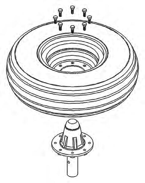
1. Stand the hubs on end (remove from transport assembly if installed for shipment) and place wheels on top and install and tighten wheel bolts.
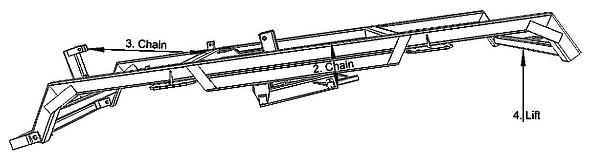
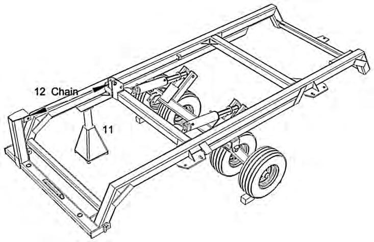
2. Use a chain or strap around the frame and the leg of the transport to keep the transport from dropping when the frame is lifted (see 4). If using a chain, place rubber or matting under the chain to prevent damage to the paint.
3. Run a chain or strap from the top of the bridle mast to the first frame cross member to keep the bridle from falling forward while working on the disk.
4. Use a forklift or other lifting device to lift the back of the disk frame high enough to slip the spindles into the axle pipes.
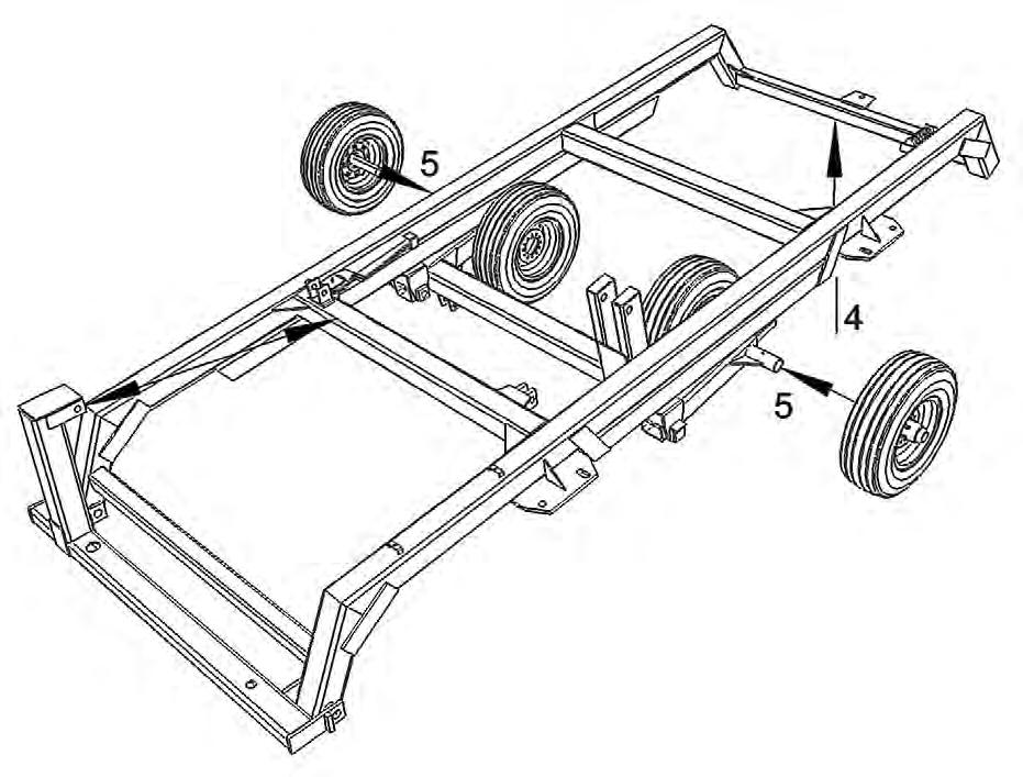
5. Slide the hub spindles into the axle pipes and install retainer bolts.
6. Lower the frame to the ground.
7. Remove the chain or strap placed around the frame and transport leg in Step 2.
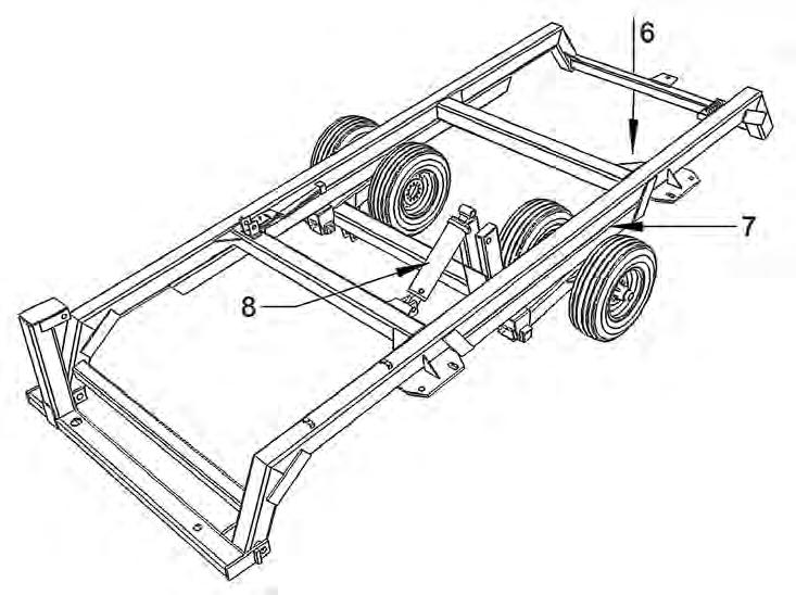
8. Attach the hydraulic cylinder to the frame at the clevis on the cross member. Remove the plugs from the cylinder ports to prevent an air lock when the rod moves in the cylinder barrel.
9. By raising and lowering the back of the frame, the rod end of the cylinder can be pinned to the transport. Once the cylinder is connected, raise the rear of the disk until the wheels clear the ground. At that point the cylinder should be fully extended.
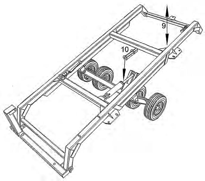
10 . Place the transport stay over the cylinder and lower the disk to the ground.
11 . Chock the tires and place a support under the front right corner of the disk frame.
12 If necessary, adjust the chain or strap between the bridle mast and frame crossmember to keep the bridle crossmember as level as possible. This will simplify the installation of the hitch.
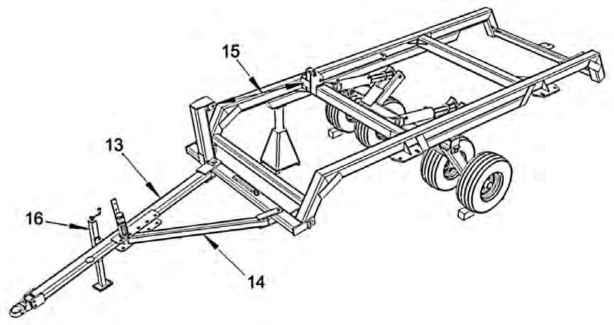
13 . Using a forklift or other suitable lifting device, attach the hitch to the bridle with the 2” fabricated bolt. Do not tighten the nut at this time. The hitch will hang from the bridle unsupported.
14 Again using a forklift or other suitable lifting device, attach the sidearm to the bridle with the bolt provided inserted up from the bottom. Do not tighten at this time. Sweing the sidearm and hitch towards each other and attach the sidearm to the hitch at the fourth hole from the front of the side plates on the hitch with the bolt provided. Tighten all the bolts.
15 . Lift the hitch slightly and remove the chain or strap from between the bridle mast and frame crossmember.
16 Attach the jack to the hitch and adjust it to support the tongue at approximately 22” (tractor drawbar height) from the ground. Attach the hose holder to the hitch.
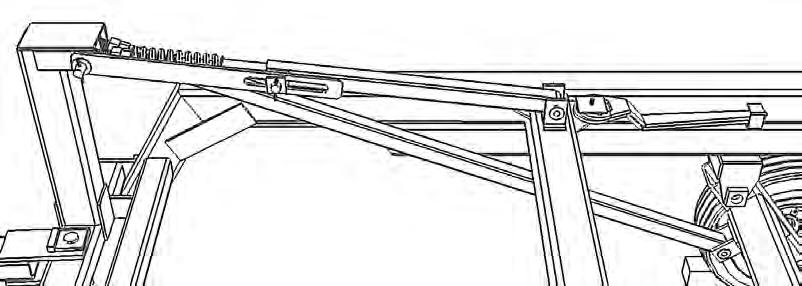
17 . Install transport control assembly. The transport control assembly consists of one threaded eyebolt on which two nuts are already installed and a length of square tube into which the eyebolt slides. The eyebolt is attached to the bottom set of holes in the mast head. The tube is then slid over the eyebolt and attached to the clevis on the underside of the transport. Once installed, tighten the nuts against the tube.
18 . Install the levelling assembly between the mast and the frame. There should be no pressure against the spring.
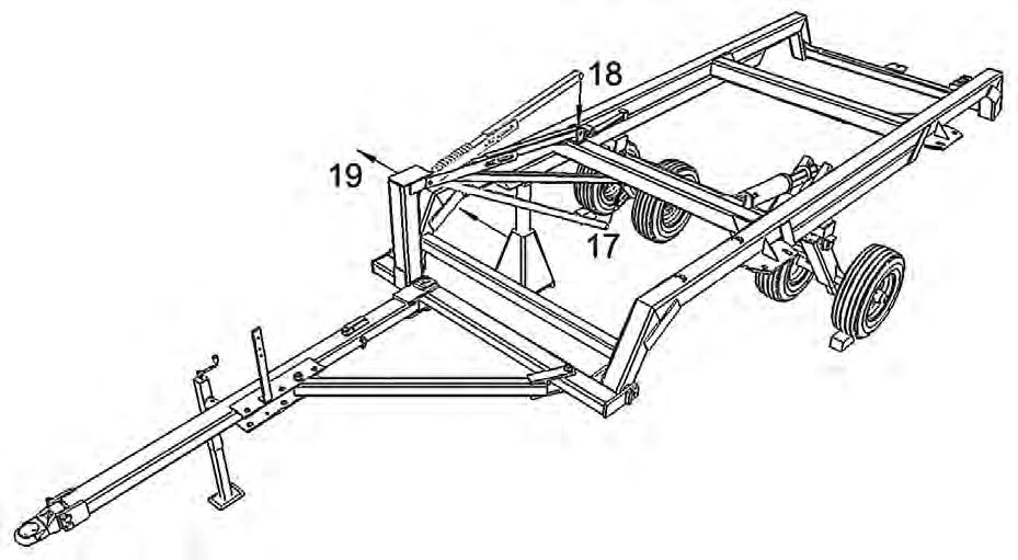
19. It is now possible to lift the hitch of the disk and remove the support from under the frame. Leave the tire chocks in place. At this point the hydraulic hoses can be connected to the cylinder but do not charge the system.
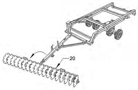
20 . Place the front gang bar assembly ahead of the hitch at an approximate 20 degree angle and with the disk blades facing the direction illustrated. When the gang bar assembly is attached to the frame the blade scrapers must be to the rear.
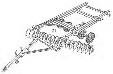
21 . Using a forklift or similar equipment, chain to the end of the hitch. Lift the hitch; unpin the jack, swivel it up and re-pin; and pulling the disk forward, lift it up and over the gang bar assembly. Drop the jack and un-chain from the hitch.
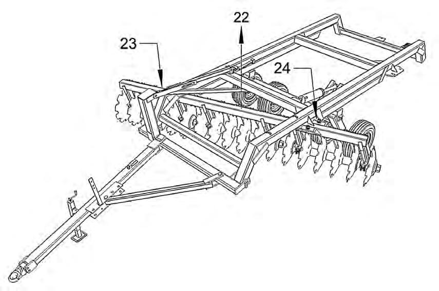
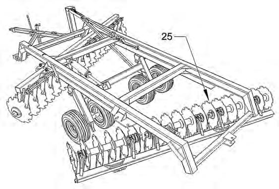
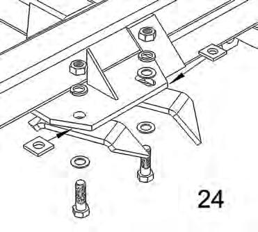
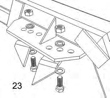
22. Using a single strap or chain of sufficient strength wraped around the center balance point of the gang bar, lift straight up throught the frame. This may require fork extensions or a boomlift. Once a single bolt and nut is installed (do not tighten), the gang bar assembly may be lowered and the chain repositioned to ease installation of the remaining bolts. A pinch bar will make this task easier. Install the bolts as per illustrations 23 and 24 on page 30.
23 & 24. Note: Gang bars deleted for clarity.
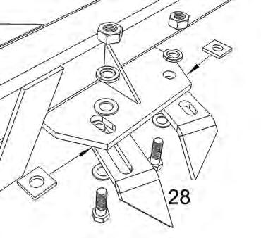
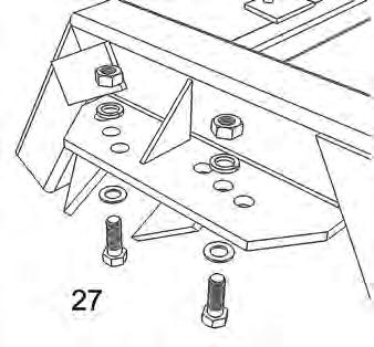
26 . Use a single strap or chain of sufficient strength wrapped around the gang bar at its center point of balance to lift the bar up to the frame. This may require fork extensions or a boomlift. Once a single bolt and nut is installed (do not tighten), the gang bar assembly may be lowered and the chain repositioned to ease installation of the remaining bolts. A pinch bar will make this task easier. Install the bolts as per illustrations 27 and 28 on page 31.
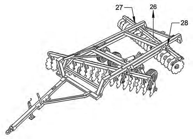
27 & 28. Note: Gang bars deleted for clarity.
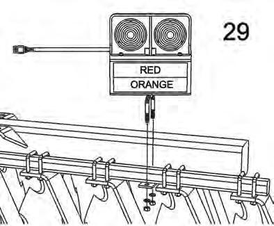
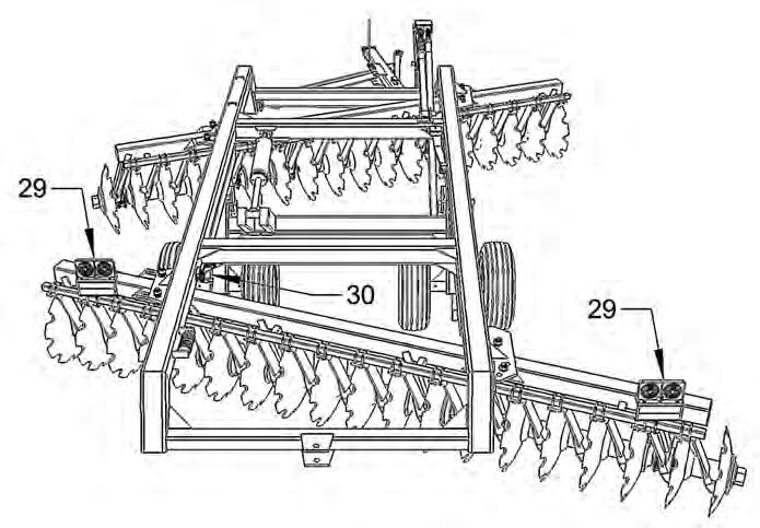
29 . Install lights on the rear gang scraper bar and within 16” of the outside extents of the disk width.
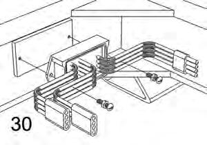
30 . Install the light kit module. Run the cables between the lights and the module as per the tags on the module pigtails indicating right hand and left hand. Run the single cable from the module to the front of the disk.
□ Plug the light connector into the tractor receptacle and check for proper operation.
□ Install the safety chain on the front of the hitch.
□ Install the hose holder on hitch and clamp the hoses to the holder.
□ If not already attached, hitch the disk to the tractor. Couple the hydraulic hoses to the tractor. Charge the hydraulic cylinder. It will be necessary to hold the hydraulic control open for a minute or two in order to completely fill the cylinder and extend the cylinder rod enough to remove the transport stay. Remove the transport stay and lift the disk up and down a number of times to purge the system of air and reveal any leaks. Replace the fluid removed from the tractor hydraulic system.
□ Check all the safety decals are present and undamaged.
Disk Gang Assembly Procedure (Rebuild Only)
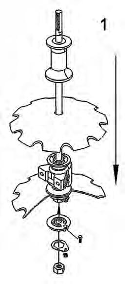
A disk gang consists of an axle on which disk blades, spacer spools an d bearings are mounted. The axle is threaded at each end. End washers are then placed on both ends of the axle. Heavy axle nuts are then threaded onto each end and tighted to a recommended torque. The axle nuts are locked into place by bolting a nut lock plate around or beside the nut and to the end washers with bolts and lock nuts. The disk blades, spacer spools and bearings have both concave and convex surfaces. Care must be taken to match convex with concave surfaces during assembly. End washers are either concave or convex and the appropriate washer should be placed at each end of the axle.
CAUTION: Gang components are heavy. Two-person assembly is recommended. Follow Safety Guidelines.
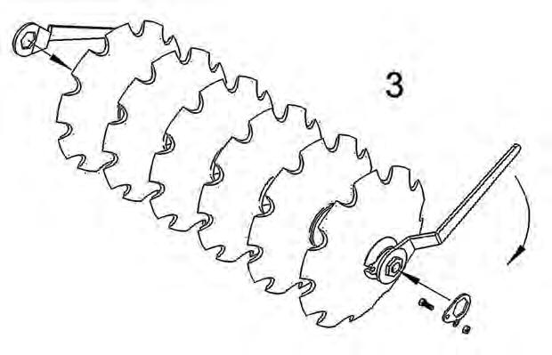
To assemble, install the convex end washer and nut on one end of the axle. Slide one blade concave side down onto the axle against the convex end washer. Next slide a bearing onto the axle, concave end first, against the disk blade. The axle can now be raised to the vertical position and it will stand without being held. In the upright position, the convex end washer should be snug against the underside of the disk blade. If necessary, tilt the axle and disk blade and place a spacer (eg. a length of 1” X 4” wood) between the nut and the floor or ground. This ensures the top threaded end of the axle will be exposed when the gang is completely stacked and the nut can be installed.
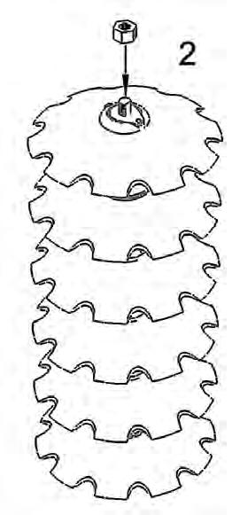
With the axle in the upright position, the remaining components can be stacked. Keep all the spacer spools between the bearings with the bearings in the outermost positions on the axle (excepting axles on which taper blades are mounted). While stacking the components, make sure all mating surfaces are free of dirt, rust, grease, grit or any other material that interferes with the mating surfaces. After the last disk is in place, drop the concave end washer into place. Apply an anti-seize compound to the axle threads and install the axle nut. Tighten the nut to remove as much slack as possible. Lower the entire assembly to the ground using hoist or forklift and chock both sides of the assembly to prevent it from rolling. Using the gang wrenches provided with the disk, tighten both axle nuts as tight as possible. It may be necessary to use a length of 2” pipe on the wrenches for extra leverage. A sledge hammer may be used to strike the wrench handle for the final adjustment to fit the nut lock plates. Install the nut lock plates over the axle nuts and attach to the end washer with the four bolts and lock nuts provided.
Detailed Parts Diagrams
□ T he illustrated parts diagrams will assist in procuring replacement parts from your Frontier Dealer. However, to be sure of receiving the correct parts, please have the Model Number and Serial Number of your disk available when ordering parts.
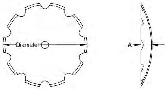
□ In the event the serial number plate is missing the following information can help to identify your disk:
the total number of disk blades on the unit. the spacing in inches between the disc blades.
□ The parts diagrams can also aid in the assembly and maintenance of your disk.
Hitch and Bridle Assembly - Models DH5210 / DH5212 / DH5214
Hitch and Bridle Assembly - Models DH5216 / DH5217 / DH5219 / DH5221
Scrapers
Gang Bars
-see page 44 5KB2R81S
Axle - 38.3" (4 Blades)
Axle - 48.8" (5 Blades)
Axle - 59.5" (6 Blades)
Axle - 70.0" (7 Blades)
Axle - 80.5" (8 Blades)
Axle Nut
Concave Axle Washer
Convex Axle Washer
Spacer Spool
Oil-Bath Bearing Assembly Bearing
Axle - 39.5" (4 Blades) Axle - 50.0" (5 Blades) Axle - 60.5" (6 Blades) Axle - 71.0" (7 Blades)
Axle
Nut Concave Axle Washer
Disc Blades
-use either 9 or 10 depending on fitment to gland.
Decals, Reflectors and Logos
Standard Equipment and Features
□ OilBath Bearings with backtoback tapered roller bearings in a ductile cast housing sealed with metal industrial cone seals. Two bearings per disk gang assembly.
□ Replaceable bearing wear plates.
□ Adjustable disk blade scrapers.
□ 15/8” diameter alloy gang axles threaded at each end (optional 21/8” axle).
□ Fabricated steel spacer spools.
□ Separate transport levelling and field levelling mechanisms simplify adjustment.
□ Hydraulic control group includes 16” stroke welded 5” diameter hydraulic cylinder with 2” rod, hose holder, hoses with fittings and quick disconnects to reach tractor couplers.
□ 11L15 Highway Service implement tires (DH5210/DH5212/DH5214) or 12.5L15 Highway Service implement tires (DH5216/DH5217/DH5219/DH5221) on 8bolt wheels and hubs.
□ Major fasteners minimum Grade 8 plated.
□ Two fabricated steel gang axle wrenches.
□ Hitch jack, safety chain and transport stay.
□ Safety decals, mounted SMV sign and Light Kit
* Drawbar Horsepower requirements vary with soil conditions, topography, weight added to the disk and tractor type (e.g. rubber track, rubber wheel, straight frame, articulated).
Note: The manufacturer reserves the right to make improvements and modifications which may, without notice, change these specifications.
DH5210
DH5212
DH5214
DH5216
DH5217
DH5219
DH5221