8 minute read
Adjusting the Transport Levelling Control Arm

from Frontier Offset Agricultural Disks DH5210-DH5212-DH5214-DH5216 DH5217-DH5219-DH5221 Operator's Manua

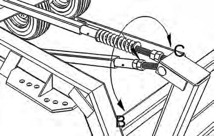
With the disk attached to the tractor, the hydraulics connected and with the transport stay removed from the hydraulic cylinder; the disk can be adjusted to transport level as in illustration A. The adjustment is carried out by turning the nuts indicated in the illustration. When the disk is raised out of the ground in the transport position, there is pressure against these nuts. Therefore, to make adjustment easier, lower the disk to the ground to take pressure off the nut. The nut can then be turned easily by hand or wrench. To lower the front of the disk as in illustration B, turn the nuts in the direction indicated as B. To raise the front of the disk as in illustration C, turn the nuts in the direction indicated as C. It may be necessary to raise and lower the disk a number of times to attain the desired result. Once the disk is level, lock the nuts together on the eyebolt shaft. This adjustment remains unchanged as long as there is no change in the tractor hitch height.
WARNING: To avoid serious injury to self or others, do not allow anybody on or near the disk when it is being raised or lowered. In particular, if someone other than the tractor operator is making adjustments to the disk, the tractor should be switched off while adjustments are being made and only restarted when that person is well clear of the disk.
Transporting the Disk
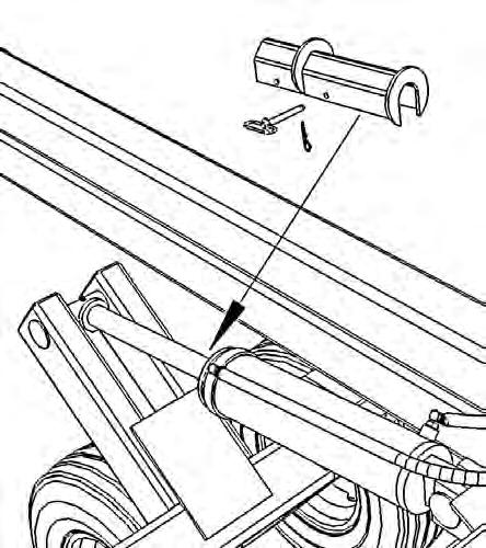
Raise the disk to its maximum height by completely extending the hydraulic cylinder. Install the transport stay over the hydraulic cylinder rod with the plated end against the head gland of the cylinder. Install the retaining pin. On tractors with open centered hydraulics, switch the tractor off and relieve the hydraulic pressure by moving the hydraulic spool lever back and forth. With closed center systems, carefully use the hydraulics to take the pressure off the hydraulics and allow the weight of the disk to be taken up by the transport stay.
Transport Safety
□ Never allow riders on the tractor or disk. Serious injury or death can result from falling in the path of the disk while in operation or transport.
□ Observe laws and regulations while transporting disk. Never transport disk at speeds greater than 20 mph (32 km/h). Reduce speed and exercise caution on turns, bridges, rough roads, steep grades and other adverse conditions.
□ Install all locking devices before transporting disk. Without these devices installed, the disk could fall during transport and cause injury or death to the operator or bystanders and/or damage to the disk, tractor and property.
□ Always used safety chains to secure the disk to the tractor during transport. Provide only enough slack in chain to permit turning. A safety chain will help control drawn equipment should it accidentally separate from the drawbar.
□ Ensure the load does not exceed the recommended specifications of the tractor. The tractor must be heavy and powerful enough with adequate braking power for the towed load.
□ Keep the SMV emblem and side and rear reflectors clean and visible.
□ Use headlights, flashing warning lights and turn signals day and night. Follow local regulations for equipment lighting and marking. Keep lighting and marking visible and in good working order. Replace or repair lighting or marking that has been damaged or lost.
□ Use the proper size and grade of pin to attach the disk to the tractor.
□ If the tractor is equipped with a swinging drawbar, be sure to pin it in the center position before transporting the disk.
□ Check wheel lug nuts for tightness and ensure tires are properly inflated and free of damaging cuts and abrasions. The failure of either of these components can cause the disk to swing uncontrollably and make it difficult to control the tractor.
□ Remove debris and loose soil from the disk before traveling on public roads. Falling debris and soil can be a hazard to following and approaching traffic.
□ Do not tow another implement behind the disk unless proper modifications have been made and it is permitted by local ordinances.
Operating Safety
□ Become familiar with the disk and its operation before using the unit. Read this manual carefully and contact your dealer if you have any questions.
□ Never allow riders on the tractor or disk. Serious injury or death could result from falling in the path of the disk while in operation or transport.
□ Be sure bystanders are clear of the disk before raising or lowering the disk. Accidental movement of the controls or hydraulic failure could cause the disk to suddenly fall.
□ Be sure bystanders are clear of the disk before operating the disk. Before entering the tractor, walk around the disk making sure no one is on, under or in front of the disk. Moving the disk while someone is between or in front of the gang assemblies could result in serious injuries or death.
□ Never work under a raised disk. Always lower the disk to the ground before inspecting or servicing. Never rely on the hydraulic system to hold up the disk.
□ Use extreme caution when working around disk blades. The blades are sharp and could cut hands, legs, etc. Wear gloves to handle disk blades or gang assemblies.
□ Do not operate close to ditches, deep bodies of water or on excessively steep slopes.
□ Before dismounting from the tractor to service or make adjustments, always
1. Lower the disk to the ground.
2. Shut the tractor off.
3. Engage the tractor’s parking brake or place transmission in park.
4. Relieve the hydraulics by moving the control back and forth.
5. Remove the key.
□ Unanticipated movement of the disk while working around the disk gangs could result in serious personal injury or death.
Operating the Disk
General Operating Guidelines
□ Use the recommended size tractor. Weight is as important as horsepower. Too light a tractor will be overpowered by the plowing action of the disk and its front end will be swung to the left, requiring constant steering corrections.
□ Always raise the disk out of the ground before turning. If pulling a harrow, roller or other toolbar behind the disk, raise the disk just clear of the ground before turning.
□ In the field do not backup with the disk in the fully raised position. Raise the disk just clear of the ground to prevent the disk from overbalancing to the rear which may damage the control arms.
□ Speed, depth and soil type and condition all determine how level the ground left behind the disk. To minimize ridging or gouging, limit the disking speed to 46 mph.
□ On tractors equipped with a swinging drawbar, allow the drawbar some movement when working in level or gently rolling fields. In severely rocky conditions, heavy clay or tree stumps allow more swing in the drawbar. In all other conditions, lock the drawbar in the center position.
□ Pulling a drag or heavy harrow behind the disk can reduce side draft and aid in levelling the soil.
Disk Adjustments
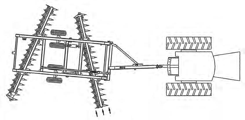
All single offset disks have a single characteristic in common. Because the front gang of disk blades are set at an angle to their direction of movement and because these blades are working in “new” ground compared to the rear disks which are working in ground already partially tilled by the front blades, a single offset disk tries to rotate clockwise as it is pulled forward through the field. To perform optimally and to reduce stress and premature wear on components, it is desirable that the machine draft in a straight line behind the tractor. As well, the concavity of the disk blades is such that in the center angle setting the blades will accomplish the most tillage with the least horsepower and minimum wear to the blades. When the disk drafts to one side (i.e. “dog tracking” or “crabbing”) the gang angles are changed and the quality of the tillage suffers.
There are three types of adjustments that affect the draft of the disk.
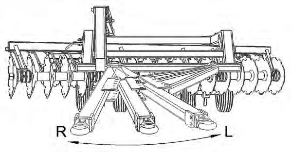
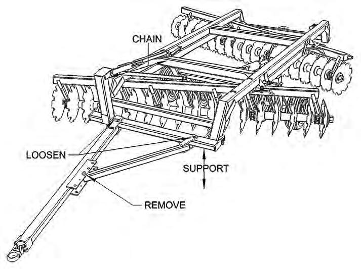
REPOSITION THE HITCH.
This adjustment is best accomplished when the disk is not attached to the tractor. SUPPORT the bridle crossbar to which the hitch and side arm are attached with a jack and stand. Alternatively the head of the bridle mast can be CHAINed back to the first member of the main frame. Next LOOSEN the bolts attaching the hitch and side arm to the bridle. REMOVE the pin attaching the side arm to the plates on the side of the hitch.
The hitch bar can be placed in five fixed positions. Moving the hitch towards “L” as illustrated will cause the rear of the disk to move to the left when viewed from behind. Moving towards “R” will cause the rear of the disk to move to the right when viewed from behind.
Swing the hitch to the desired position and reattach the side arm through the appropriate bolt holes in the plates on the side of the hitch. Tighten the 1-1/4” bolts and 2” fabricated bolt to approximately 1300 ft/lbs ft/lbs and recheck after the next 10 hrs of use.
Change The Gang Angles
Position A indicates the optimal gang angle and is the setting which yields the best performance while minimizing blade wear. The second setting is intended to extend the useful life of the disc blades. Blade wear is equivalent to decreasing the gang angle. To maintain performance of worn disk blades, the gang can be moved to position B to maximize blade usage.
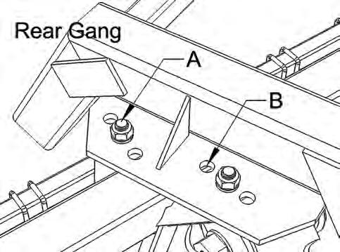
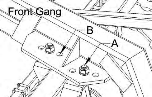
To change the angle of the front gang, loosen the bolts at positions A and remove the bolts at positions B. With the disks slightly lowered into the ground, use the tractor to carefully move the disk either forward or backwards to the desired position. Reinstall bolts B and tighten all four bolts to 400 ft/lbs.
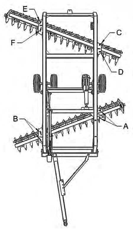
To change the angle of the rear gang, loosen the bolts at positions C and D, and remove E and F. The rear gang of the disk can also be adjusted from side to side. If the rear gang is moved to the left, it increases the amount of soil being thrown into the furrow. If the rear gang is moved to the right, it will decrease the amount of soil being thrown into the furrow. To shift the rear gang, loosen the bolts at positions D and E and remove the bolts at C and F. With the disk blades resting on the ground, moving the disk either forward or backward will cause the gang carrier to shift to the right or left as desired. Align the bolt holes, reinstall the bolts and tighten all four bolts to 400 ft/lbs.
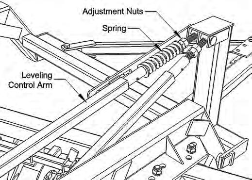
Adjust The Leveling Control Arm
The leveling control arm is used to transfer pressure to the rear of the disk in order to increase penetration of the rear disk blades. Pressure is increased by tightening the adjustment nut against the spring. This adjustment is easiest to make when the disk is in the raised transport position and there is no pressure on the nut. Once the desired setting is made, lock the first nut with the second nut on the eyebolt. When the disk is lowered to the operating position, take care the spring is never fully compressed. Increasing pressure against the spring will put more down pressure on the rear blades. Carrying the disk slightly with the wheels while operating will allow the disk to pivot on the wheels and result in more even blade penetration front to rear. If the disk is operated with the wheels fully raised, little or no pressure should be placed on the spring. If disking through a sharp depression or ditch, raise the disk slightly to prevent excessive pressure on the spring and levelling arm.
Increasing pressure on the rear gang can reduce dog tracking by creating a side thrust opposite to the thrust of the front gang.