21 minute read
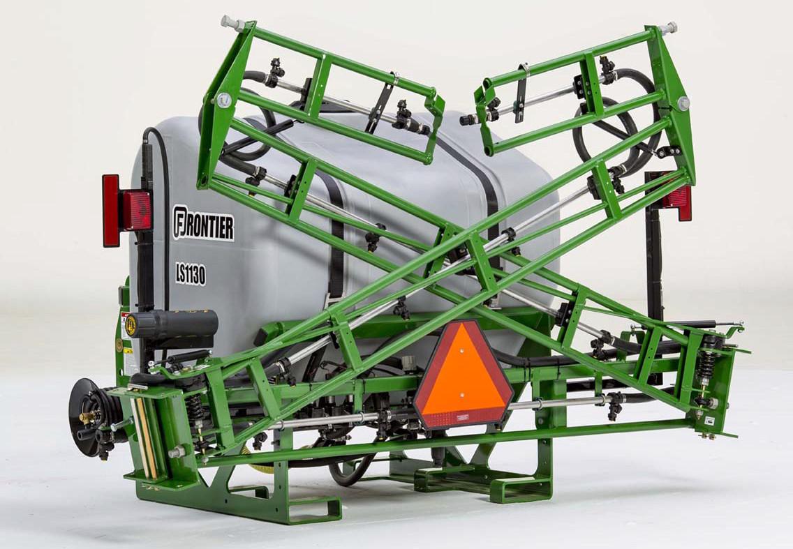
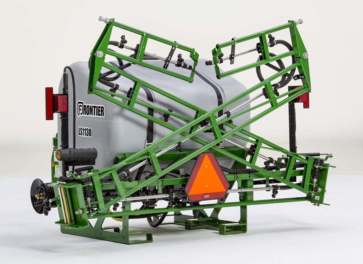
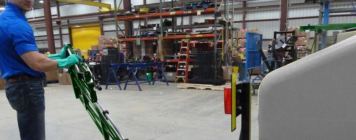
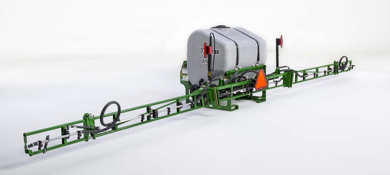
ATTACH SPRAYER TO TRACTOR


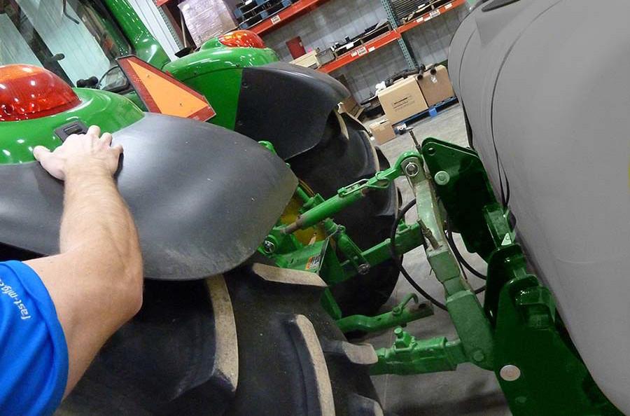
Keep hands and body out of hitch area when attaching to the tractor.
Clear area of bystanders.
Use caution when connecting controls to avoid pinch points.

NOTE: The 3 point hitch on your tractor may be different than the 3 point hitch shown. Consult the owner manual for the 3 point hitch eq uipped on the tractor.
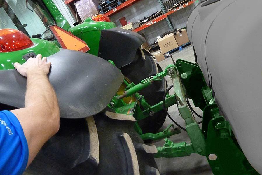
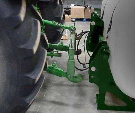
1.Lower the lift arms on the tractor to the lowest point.
2.Align the lift arms with the sprayer hitch.
3.Back up slowly until the lift arms make contact with the hitch and are in position under the hitch pins.
NOTE: If using external hitch controls stop tractor engine, place all controls in neutral, set park ing brake, and wait for all moving parts to stop before leaving the tractor seat.
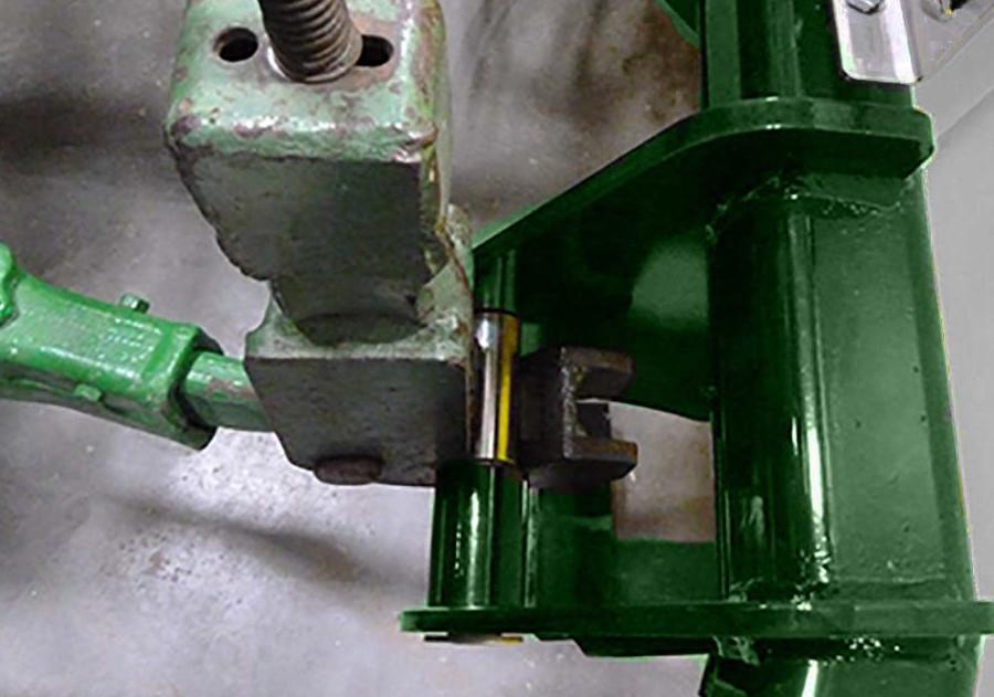
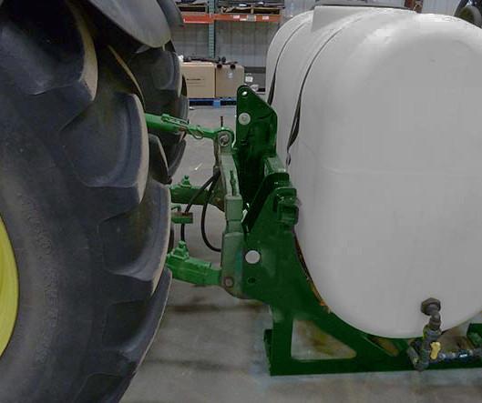
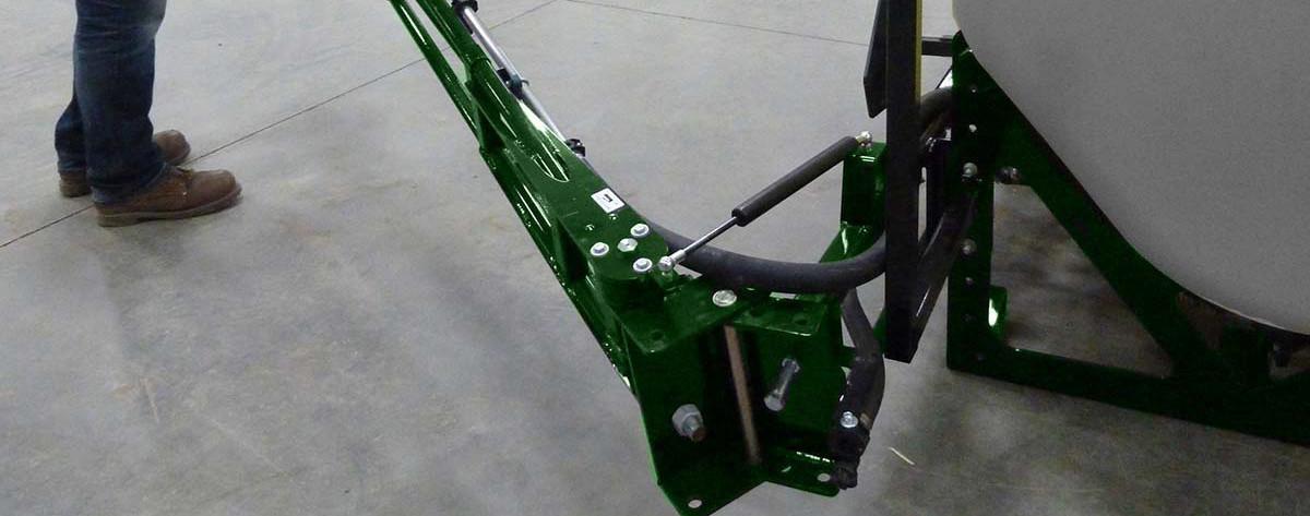
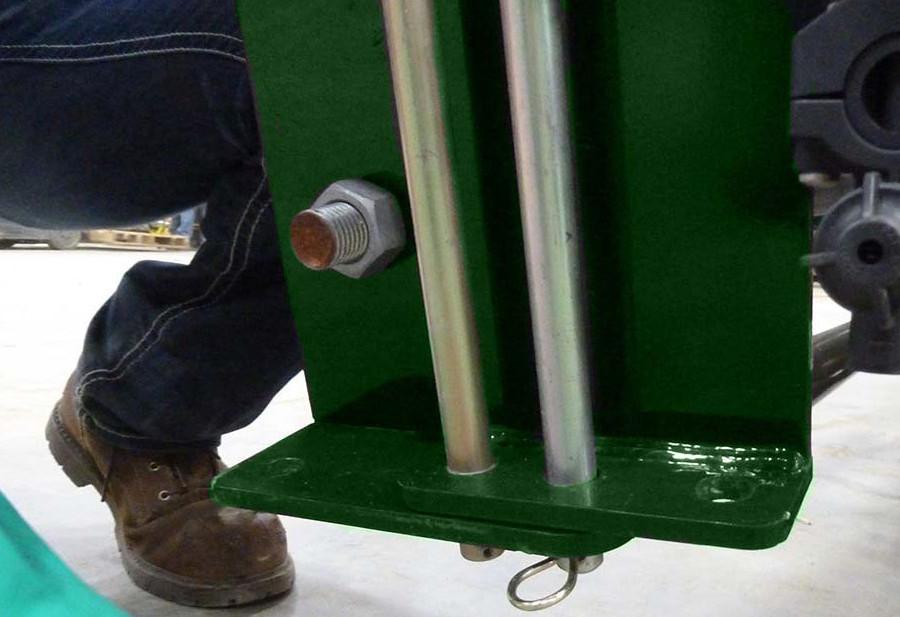
4.Slowly raise the lift arms to hook onto the sprayer hitch pins.
Caution: Avoid crushing! Keep away from sprayer and hitch area when raising.
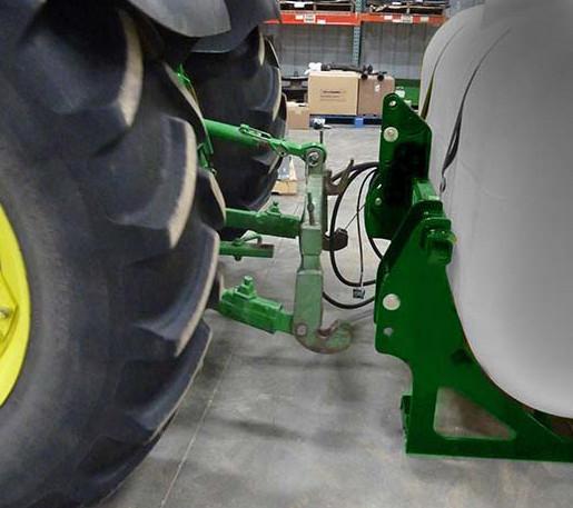
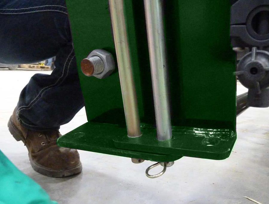
5.Check that all three lift arms have locked on to t he sprayer hitch.
6.Engage safety latches on the 3 point hitch.
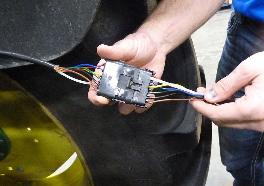
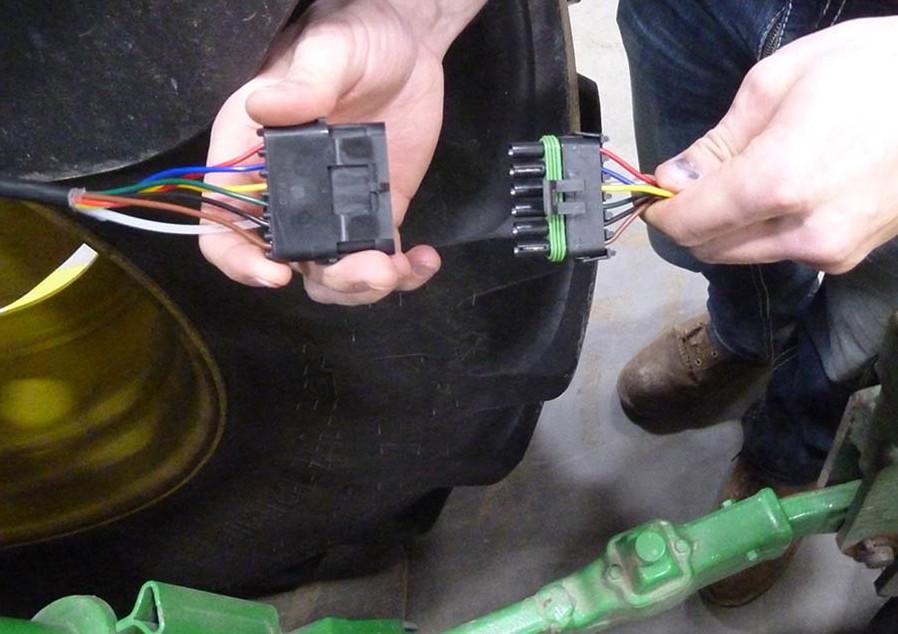
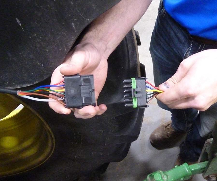
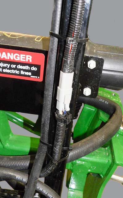
7.Connect the sectio n valve controller harness.
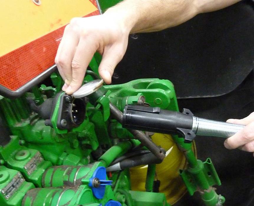
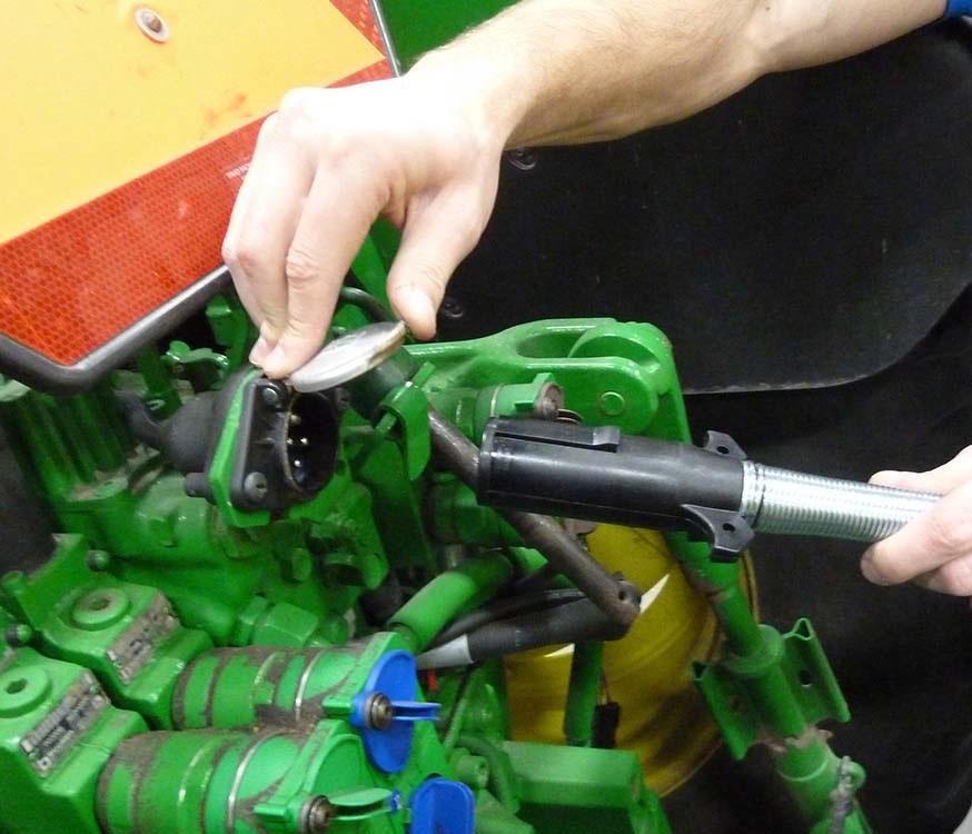
8.Connect the light harness
•Align the plug ends.
•Open the light harness port on the tractor.
•Align the harness to the tractor light harness port.
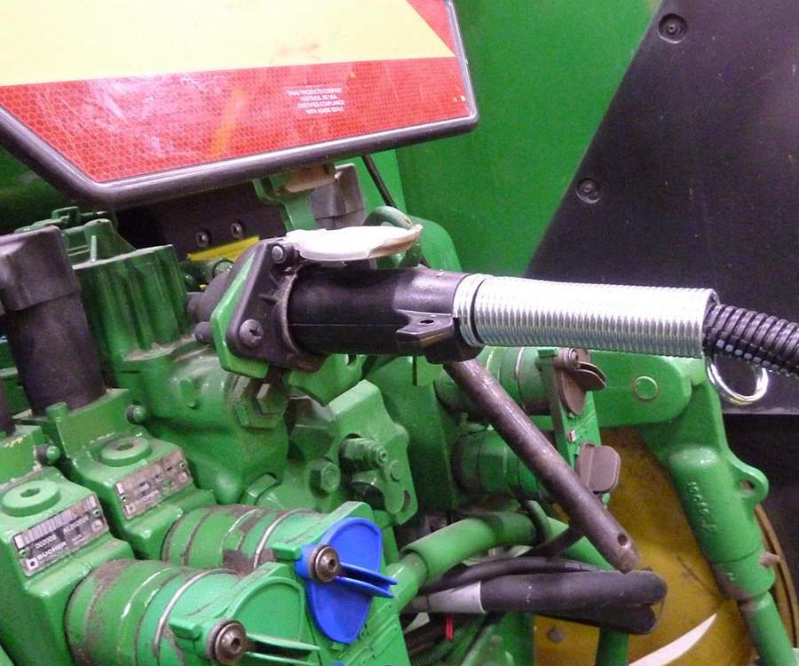
•Push harness into port until tight.
•Push the plug together until it is tight.
Caution: Avoid Pinching Injury. Keep hands clear of connections.
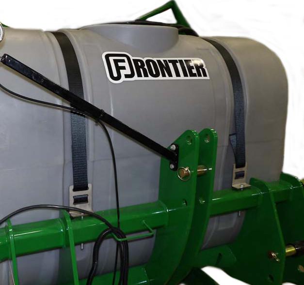
If the sprayer is equipped with hydraulic controls:
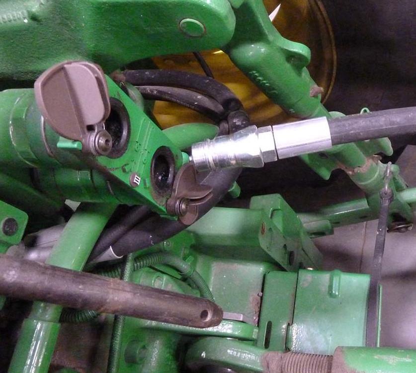
NOTE: Clean the hydraulic port area and hose couplings before attaching to prevent getting debris in the hydraulic system.
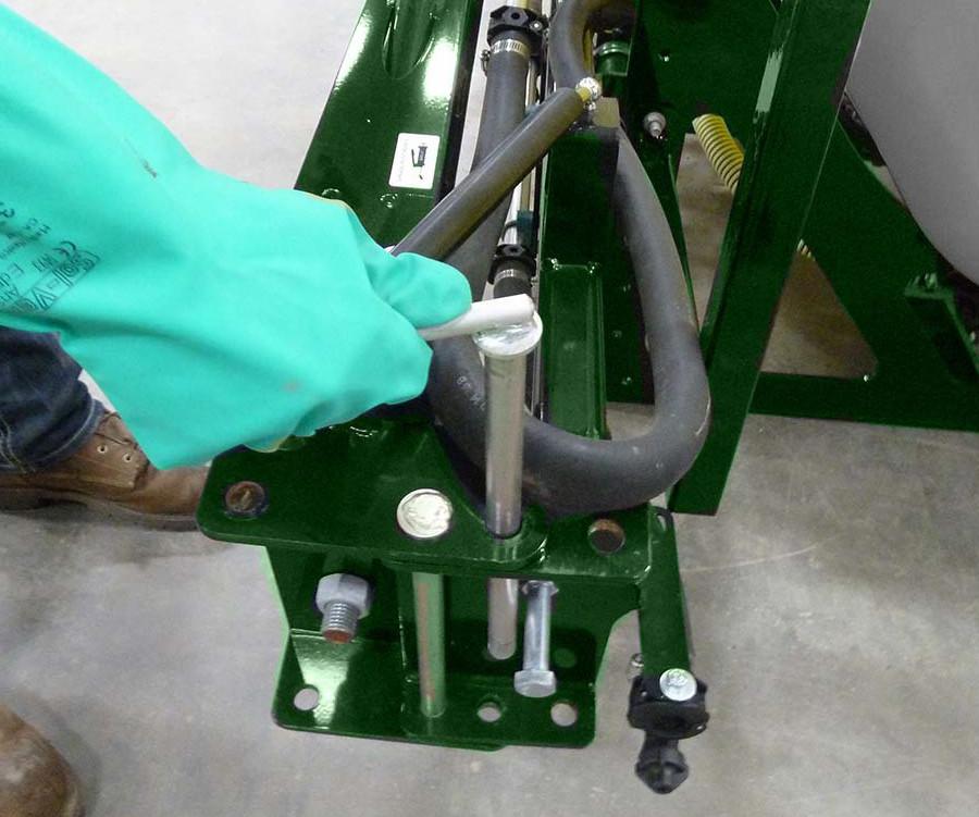
1.Connect the hydraulic lines.
•Open the hydraulic port on the tractor.
•Align the hose coupling with the tractor port.
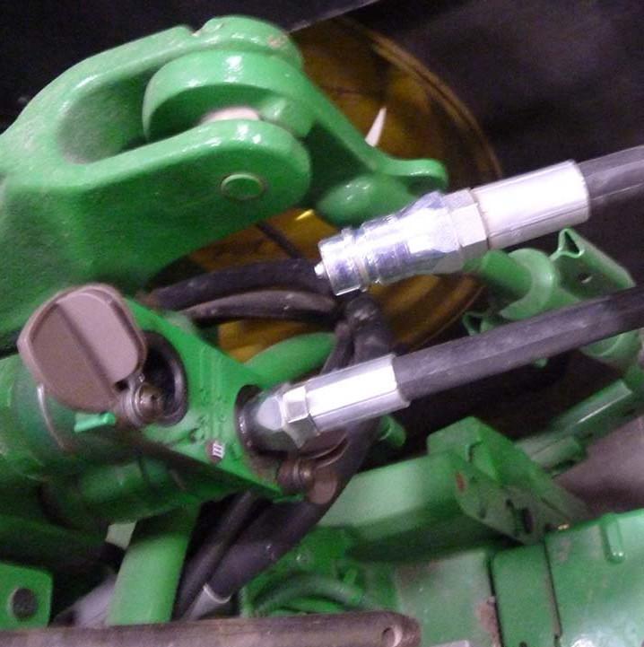
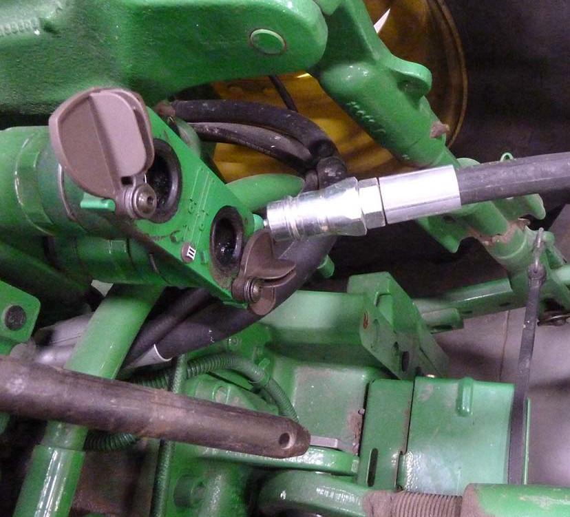
•Push the coupling into the port until it locks.
2.Repeat to connec t second hydraulic line.
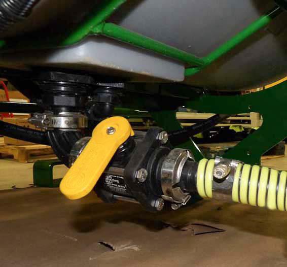
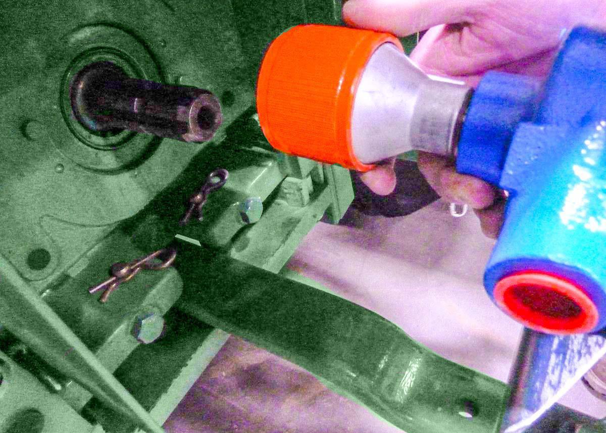
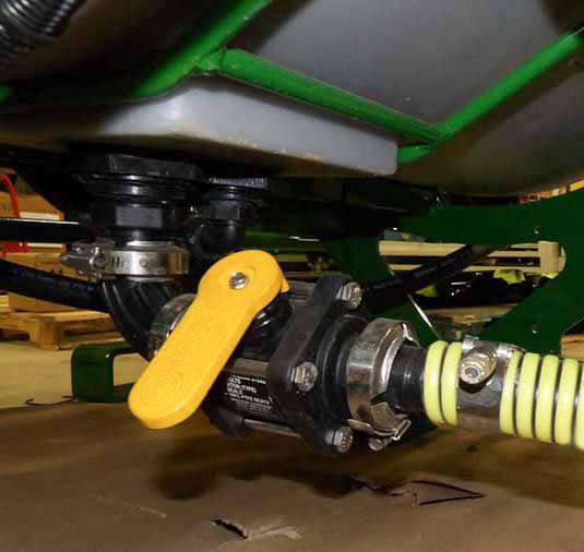
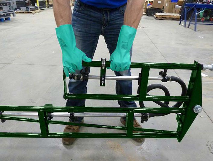
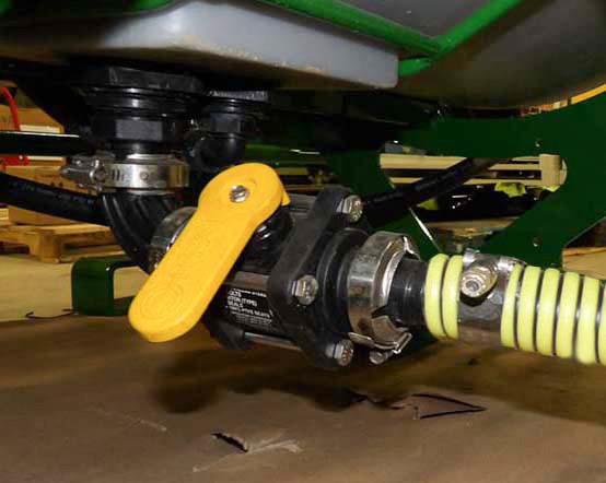
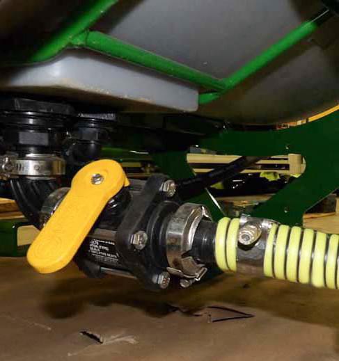
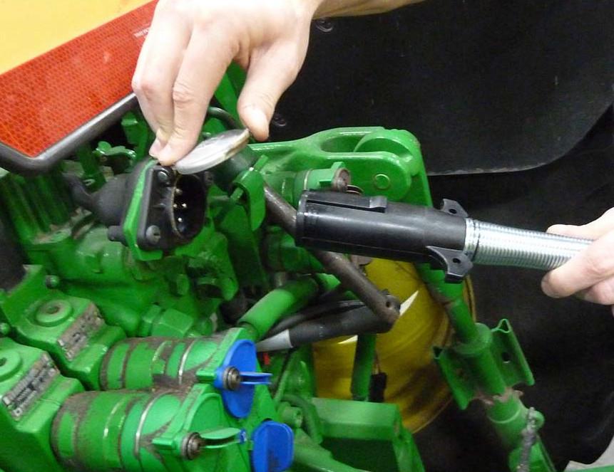
If the sprayer is equipped with a PTO pump system:
1.Connect PTO Pump.
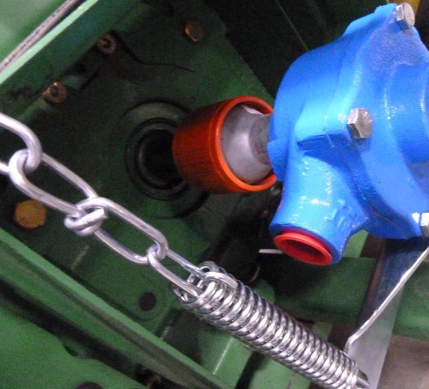
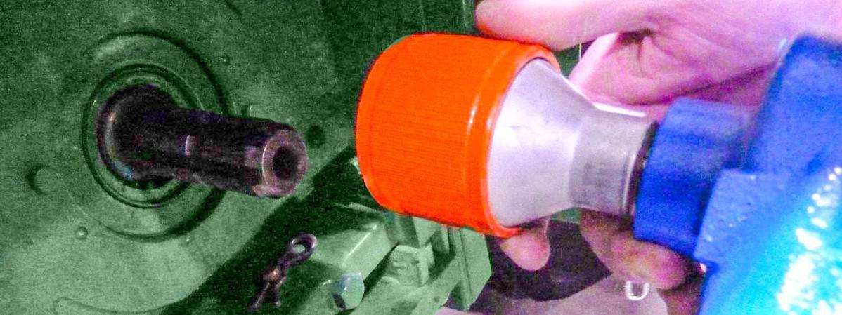
•Align PTO Pump with the PTO shaft
CAUTION: Avoid Pinching Injury. Keep hands clear of connections.
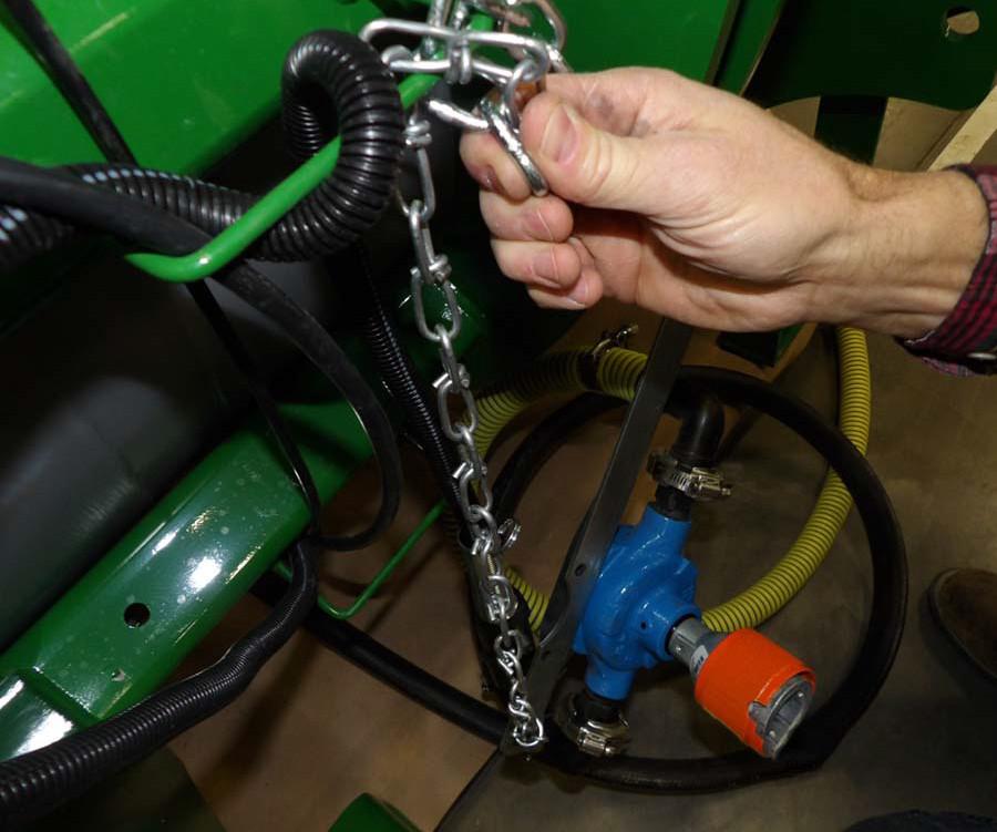
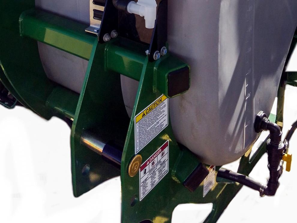
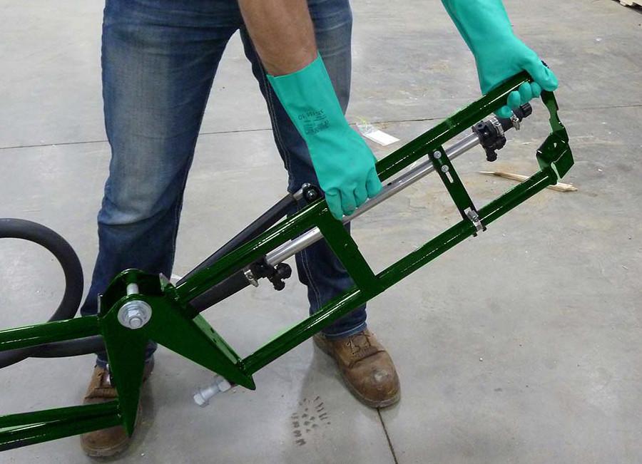
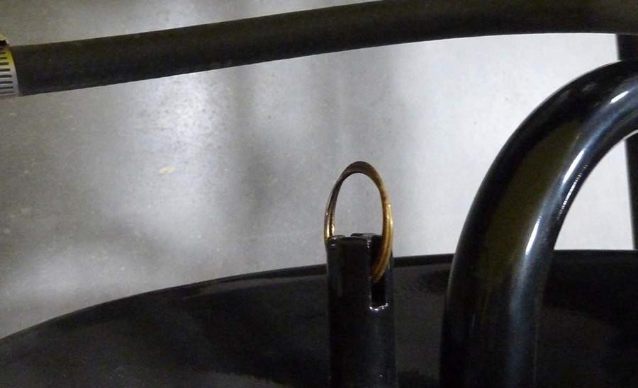
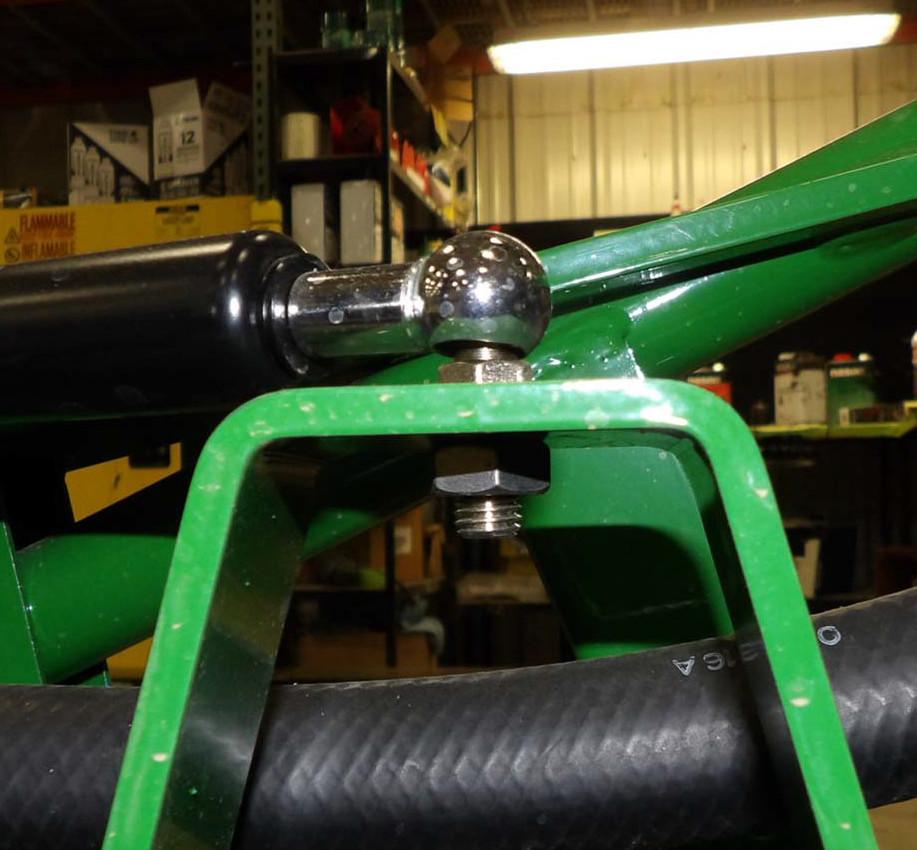
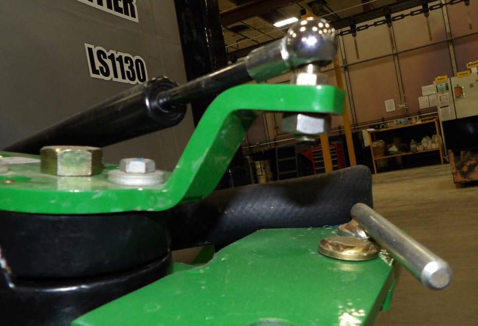
2.Brace torque arm against solid member of tractor frame in the direction of the PTO rotation. DO NOT brace against the 3-point li ft arms or any other moving parts.

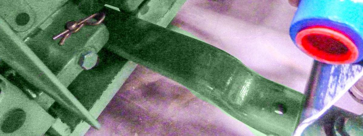
3.Connect chain fairly tight to the tractor frame in the opposite direction. We recommend using the drawbar (if possible) and wrappi ng the chain as shown above.
Detach Sprayer From Tractor
Stop tractor engine, place all controls in neutral, set parking brake, remove ignition key and wait for all moving parts to stop before disconnecting.
Wait for chemical spray to stop before approaching the sprayer. Clear the area of bystanders.
Use caution when disconnecting controls, and folding wings to avoid pinch points.
Use caution when lowering sprayer to avoid crushing injury. Say clear of hitch area.
1.Move the sprayer to a level area.
2.Lower the sprayer to the ground.
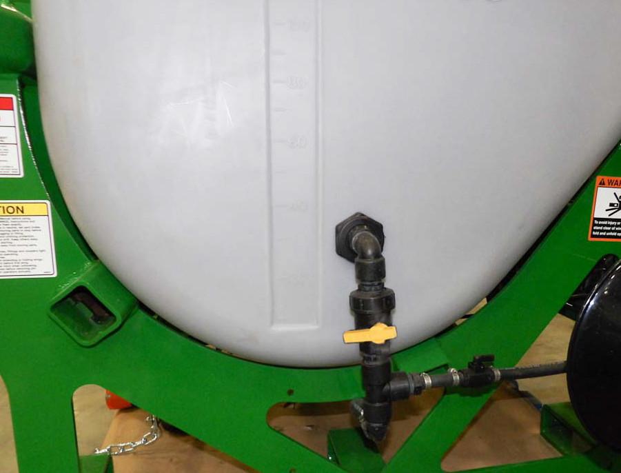
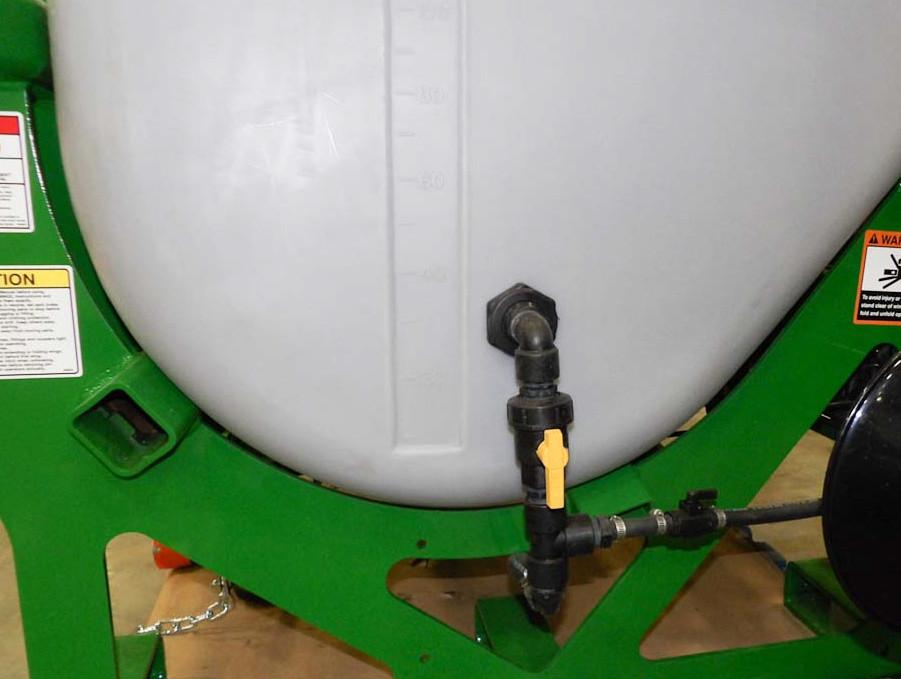
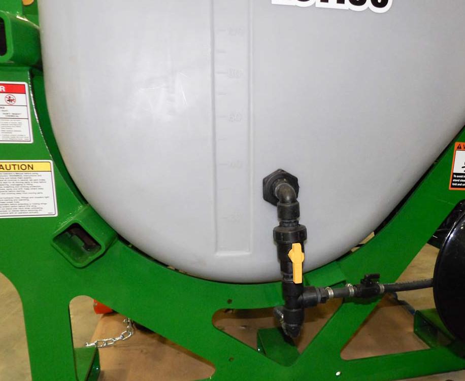
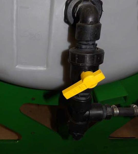
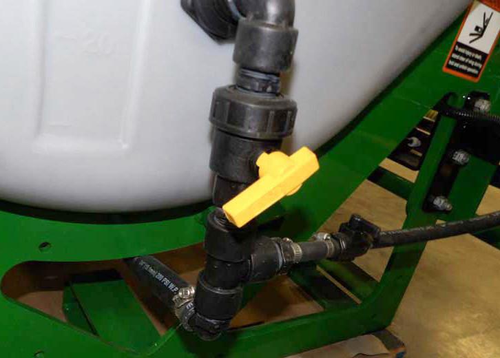
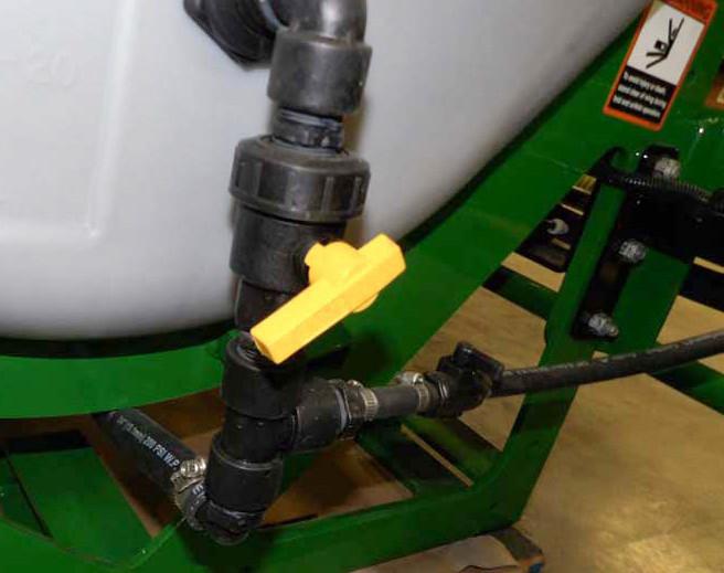
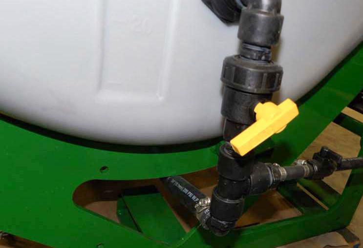
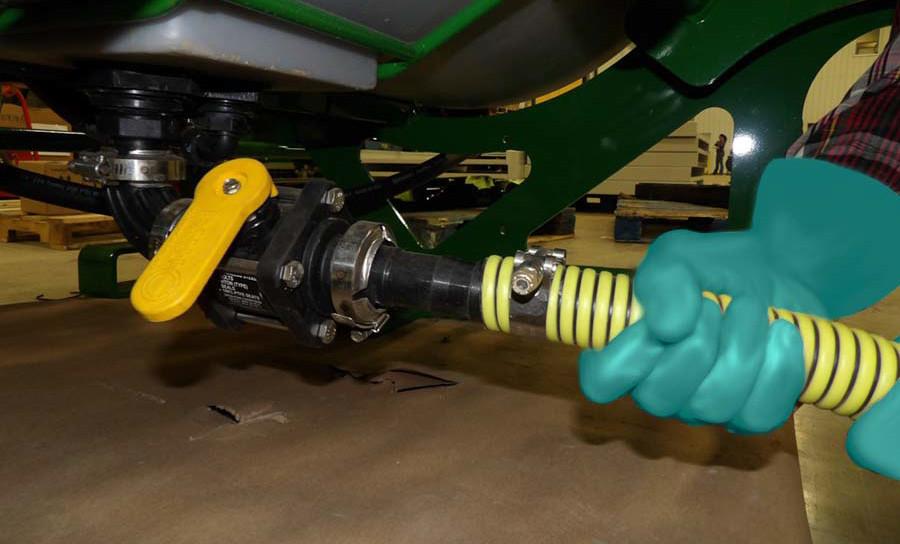
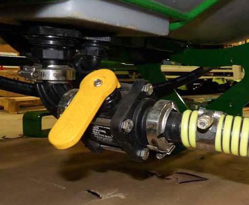
3.Close the tank valve.
•Turn valve handle 90° from hose line.
4.Fold wings into transport position.
•Depress the clip on the plug to connector while gently pulling connector apart
•Do not jerk or force connection apart or pull by the cords.
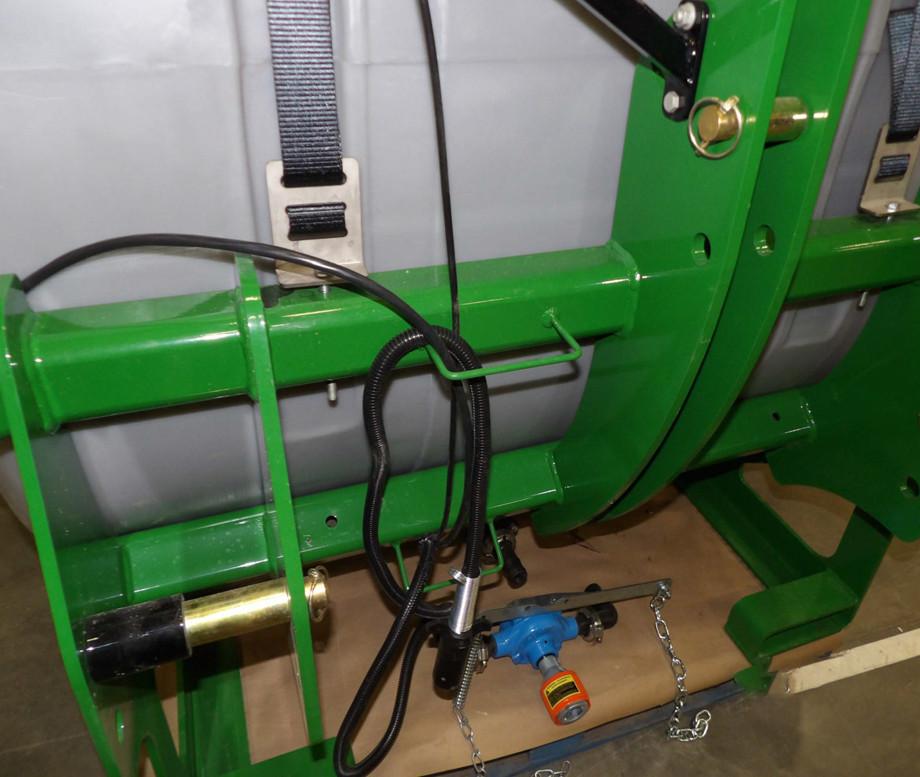
6.Secure the controller cord in the cab.
7.Hang the controller connection cord on the provided cord holder on the sprayer.
If the sprayer is equipped with a PTO pump: Disconnect the PTO pump.
8.Disconnect
•Depress clips on coupling.
•Pull harness connection away from port.
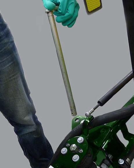
•Disconnect the torque chains.
•Depress release button fully.
•Pull pump away from tractor.
CAUTION: Avoid Pinching Injury. Keep hands clear of connections.
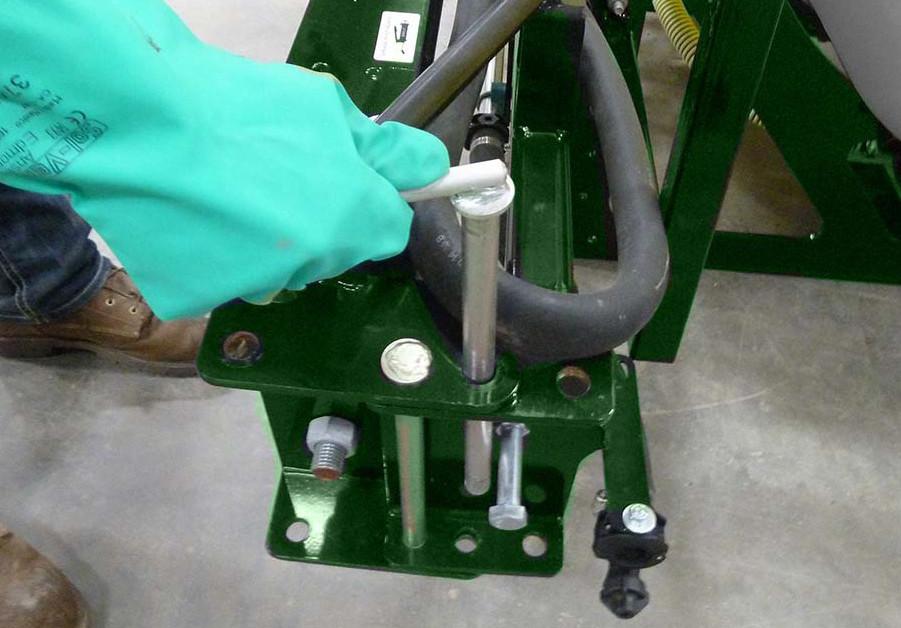
Store PTO pump by looping the torque chains around the provided cord holder on the sprayer. Use a bolt to secure.
IMPORTANT: Store the PTO pump with the connection facing out or down to prevent rain water getting in the line.
If the sprayer is equipped with hydraulic motor driven chemical pump:
Disconnect the hydraulic lines.
10.Lower the lifting arms until the links are below and clear from the hitch pins.
•Relieve hydraulic pressure.
•Depress the hose coupling to release.
•Repeat to disconnect second line.
9.Release latches and slowly lower the lifting arms to unhook.
CAUTION: Avoid crushing! Keep away from sprayer and hitch area when lowering.
11.Slowly drive tractor away from sprayer.
CAUTION: Avoid crushing! Keep away from sprayer and hitch area when lowering.
Transporting
Review the Transportation Safety section of this manual.
Know and follow all applicable laws and regulations for transporting equipment.
Do not allow riders.
Do not exceed 20 mph (32 km/h) when transporting.
Slow down on uneven ground, slopes, curves, or adverse conditions.
Stay away from overhead power lines.
Tank must be empty when transporting on roadways.
1.Wings must be folded in and pinned into the transport position.
3.Verify that the tank is empty.
4.Close the agitation valve.
See “Fold Wing Sections” on page41.
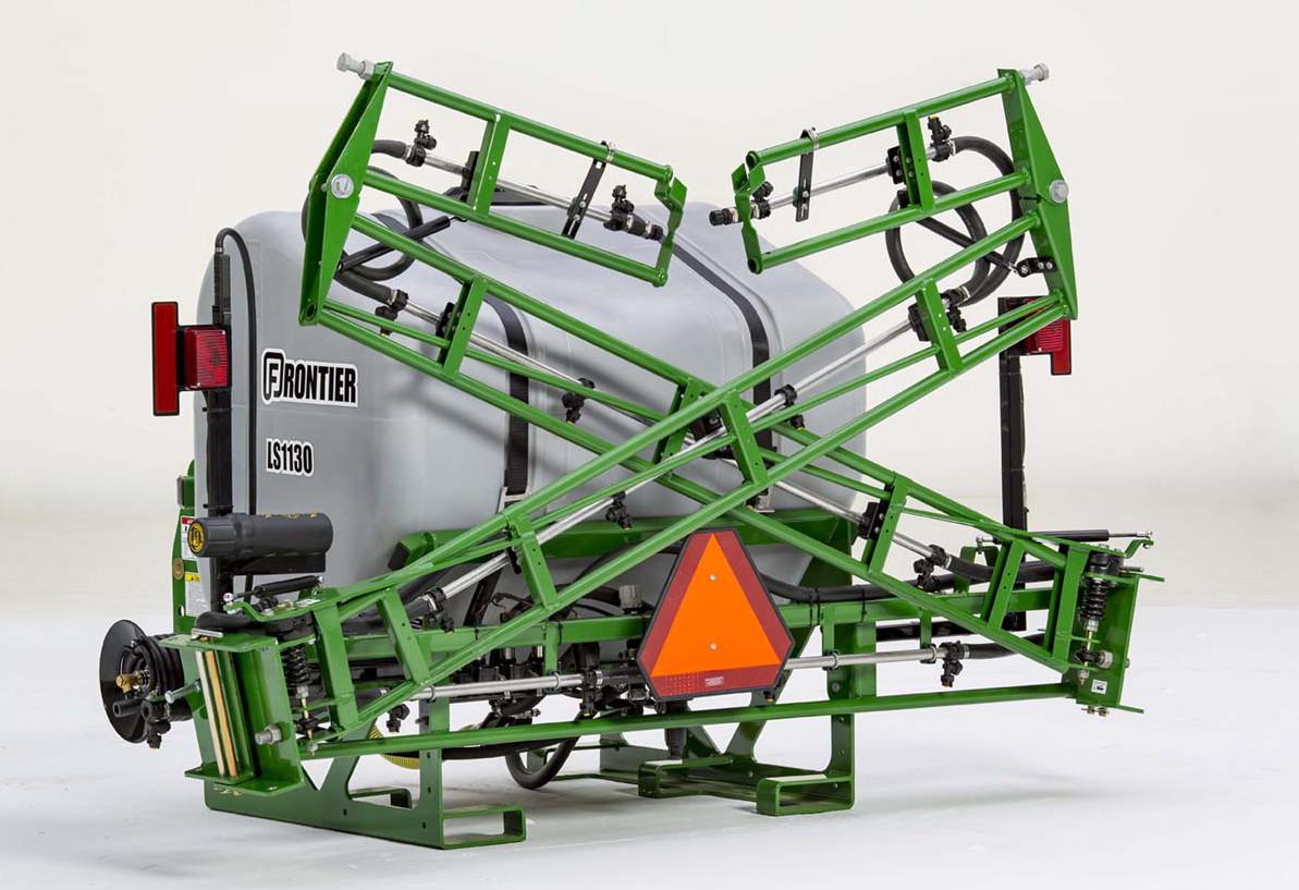
2.Check that tailli ghts are clean and operational. Check that reflectors and SMV sign are in place and clean.
•Turn valve handle 90° to fully closed.
5.Close the tank va lve before transporting.
•Turn valve handle 90° to fully closed.
Operation
Pre-Operation Checklist
The operator is responsible for the safe, responsible, and proper operation of this equipment. Failure to follow the instructions in this manual, on decals, and on the chemical SDS sheet coul d result in injury, death, damage to crops , equipment or the environment.
Perform these checks before operation:
1. This sprayer is intended to be used ONLY on vehicles with an enclosed, pressurized operator station.
2.Read and underst and the Operator’s Manual and all safety signs on the equipment.
3.Read and underst and the chemical manufactures information.
4.Check that this manual, SDS sheets and chemical information and emergency contact information is on board the sprayer.
5.Know and follow al l state, federal and local regulations fo r use and transport of this equipment and handling of chemicals.
6.Clear the working area of bystanders.
7.Gather required PPE for the job. Put on the required PPE before filling, operating, or servicing the sprayer.
8.Ensure the tractor is of adequate power and size and is in good working condition.
9.Check condition and placement of fluid lines. Check for leaks and that fittings are tightened.
10.Verify that any repair and all maintenance has been competed, including lubrication.
11.Check the weather conditions, spray only when the potential for chemical drift is minimal.
Field Operation
1.Read and underst and the Operator’s Manual and all safety signs on the equipment.
2.Follow the Pre-Op eration Check List.
3.Spray only when potential for chemical drift is at a minimum.
4.Be aware of obstacles and hazards in the field to be sprayed.
5.Do not allow riders on sprayer or tractor.
6.Clear the area of bystanders.
7.Calibrate the sprayer, or verify calibration is correct for the job.
8.Calculate the amount of water and chemical needed for the field(s).
9.Attach the sprayer to the tractor.
10.Review location and function of all controls.
11.Put on PPE. Fill the tank with the exact amount of chemical solution needed.
12.Stop tractor, set parking brake, remove key and wait for al l moving parts to stop before leaving tractor seat.
13.Unfold boom wings.
14.Open tank valve and adjust agitation valve to positi on determined when application rate was calibrated.
15.Proceed into the field at a constant speed. Use the same gear, engine RPM, and ground speed determined when application rate was calibrated.
16.Operate the controls to turn on boom sections. Monitor and adjust pressure.
17.When spraying job is complete turn off section control switches and close tank valve.
18.Follow the procedu re to rinse the tank. See “TANK MAINTENANCE AND SERVICE” on page58.
19.When rinse is complete, stop tractor, set parking brake, remove key and wait for all moving parts to stop before leaving tractor seat.
20.Close tank valve.
21.Fold wings into transport position.
22.Transport sprayer to storage location.
23.Disconnect sprayer from tractor.
Fill the Tank
Read and follow the chemical manufactures warnings and follow instructions exactly.
Put on the PPE required on the chemical SDS sheet.
Clear bystanders from the area.
Know your working location and how to seek medical attention in an emergency.
Do not put your head or body into the tank.
Keep face away from tank when opening to avoid pressurized chemical spray or vapor.
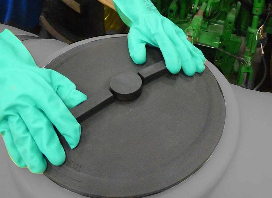
Keep hands on top of tank lid when turning to avoid pinching injury.
1.Transport the sprayer to the fill area, or fill truck in the field.
2.Lower the sprayer to the ground.
3.Stop tractor engine, place all controls in neutral, set parking brake, remove ignition key and wait for all moving parts to stop before filling tank.

4.Calculate the exact amount of chemical and water needed for the job.
IMPORTANT: Follow chemical manufactures instructions exactly.
5.Close the tank valve.
•Turn valve handle 90° from hose line.
NOTE: Clean dirt and dust from the tank cover and surrounding tank to prevent getting dirt in the tank.
CAUTION: Keep face away and open the tank cover slowly, pressurized chemical vapors or mist may escape.
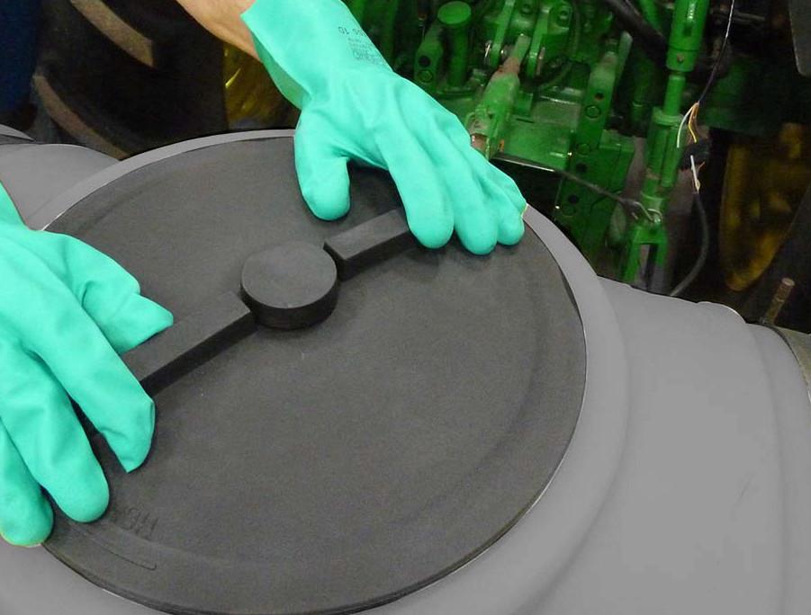
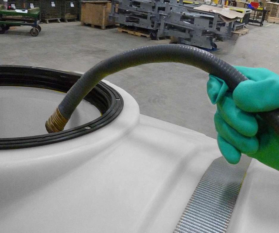
6.Remove tank cover.
•Turn the cover counter clockwise to open.
CAUTION: Avoid Pinching Injury. Keep hands on top of tank lid when turning.
Cover is tethered to the tank.
• Lay cover against tank.
7.Follow chemical manufacturer’s directions for adding chem ical to the tank.
8.Insert wate r hose into tank. Be sure hose is far enough in the tank to prevent spilling.
Do not over fill the tank.
11. Lift water hose above tank before turning off to prevent drawing chemicals into hose line. Turn off hose. Allow fluid to drain before removing hose.
•Hold hose in tank to prevent it from coming out of the tank.
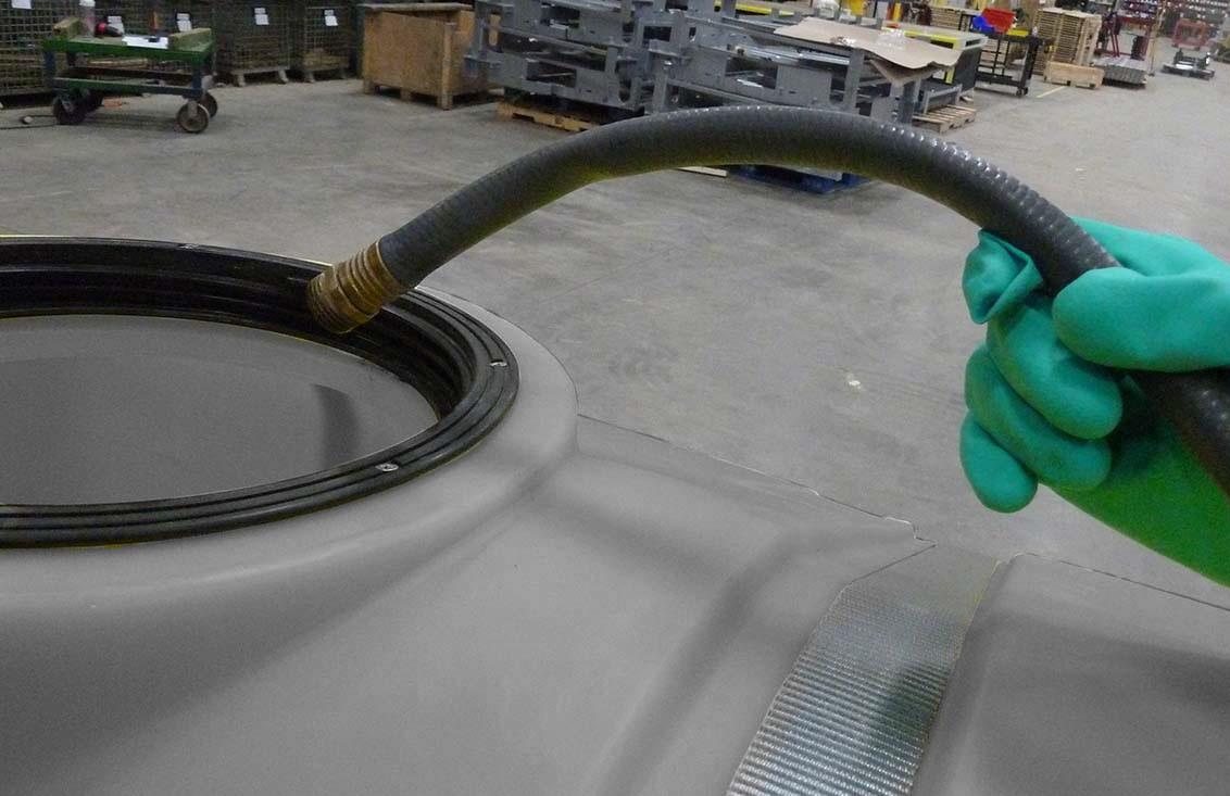
9.Slowly turn on hose. Use a low pressure to prevent sp lashing and spilling.
10.Fill tank with required amount of solution. Use the tank scale on the side as a guide.
12.Remove and properly store hose.
13.Replace the cover.
•Turn cover clockwise until tight.
Rinse Tank
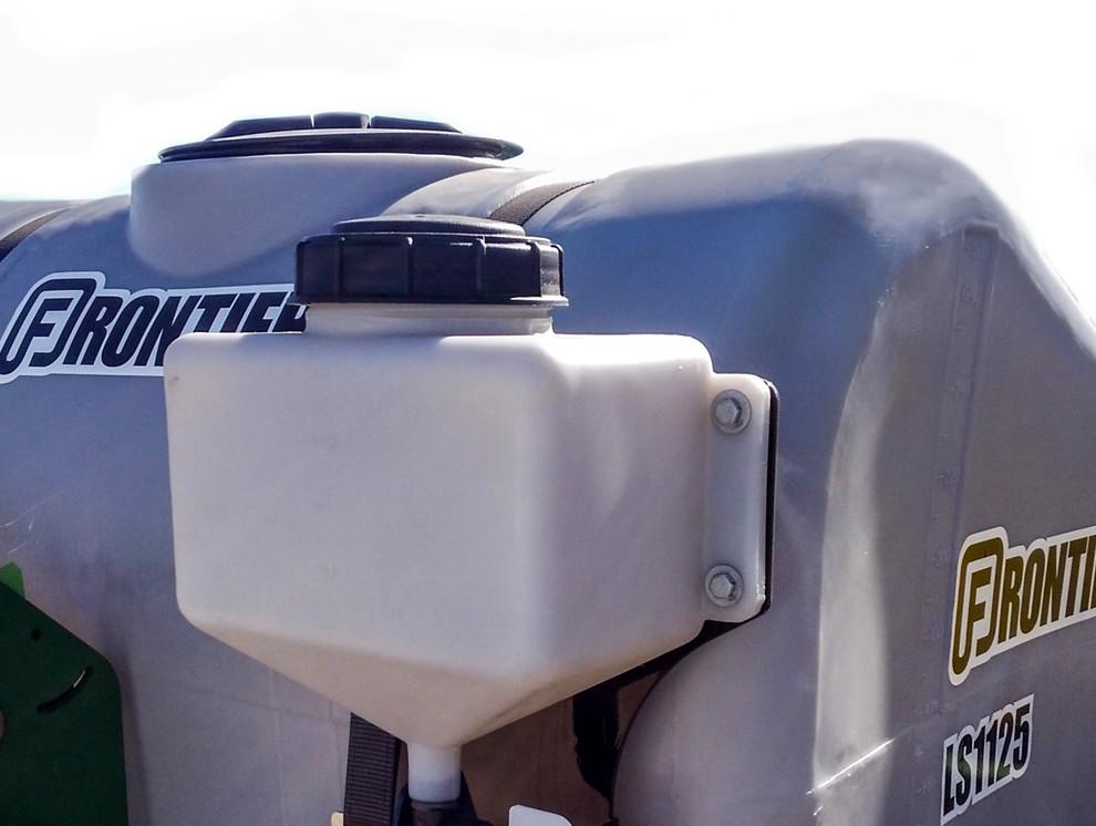
Rinse Tank
To fill the tank:
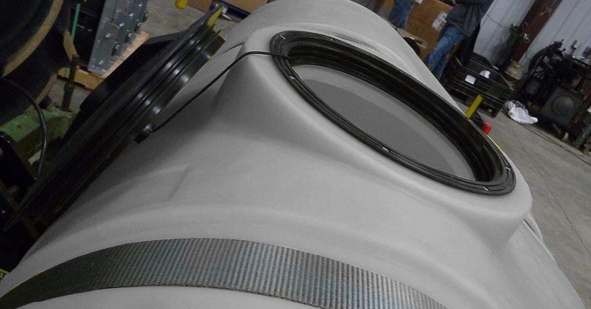
1.Twist the cover on t op of the tank to open.
2.Fill the tank wit h clean water only.
3.Replace and tighten the cover.
To use:
1.Turn the lever on the spigot to open.
2.Close spigot when finished.
Drain the rinse tank completely after using the equipment and before storing.
WARNING! Do Not drink the water from the rinse tank.
The rinse tank may become contaminated with sprayer chemicals or other contaminants.
The rinse tank is provided to allow chemicals to be washed and rinsed from hands in the field, when necessary.
The rinse tank should only be used if running water is not av ailable, and is not a substitute for washing with running water.
Operators must always throughly wash according to the chemical label instructions after handling ch emicals, this equipment or before ea ting and drinking.
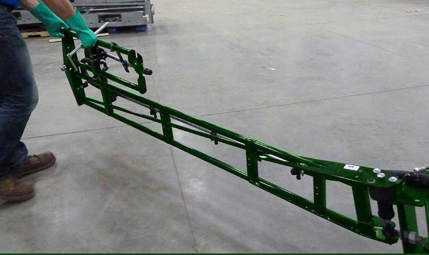
Unfold Wing Sections
Stop tractor engine, place all controls in neutral, set parking brake, remove ignition key and wait for all moving parts to stop before folding or unfolding the wings.
Put on PPE as required on the chemical SDS sheet.
Clear area of bystanders.
Clear the area of obstacles.
Stay away from power lines.
Keep away from pivot points when folding to avoid pinch points.
NOTE: For Boomless Models proceed to “CONTROLS” on page46.
NOTE: For Hydraulic Models proceed to “Unfolding Hydr aulic Wings” on page43
NOTE: Wings must be unlocked at the pivot before unfolding.
1.Unfold the left side wing first.
CAUTION: Keep away from area between wings when unfolding to avoid pinching.
5.Open
CAUTION: Keep away from area between wings when unfolding to avoid pinching.
8.Hold the flip wi ng with both hands and rotate the flip wing 180°.
•Gas shock will pull wing into position.
•Wing will rest on the stop bolt.
7.Insert
NOTE: Gas shocks provide an over centering to hold wing sections in storage or field positi ons when rotated 180º.
9.Repeat to fold out right wing.
Field Position
Inspect the followi ng in field position before use:
1.Wing sections:
•Check for bent or damaged sections. Repair or replac e damage before using.
2.Inspect wet booms and hoses:
• Check for pinches, kinks, wear or damage. Replace worn or damaged parts.
•Check that connections are tight and not leaking. Ti ghten if needed.
3.Inspect nozzles:
•Check for damaged, loose, missing nozzles. Replace damaged or missing nozzles and ti ghten if loose.
4.Inspect breakaway clutch
•Check that the clutch is aligned correctly and lubricated.
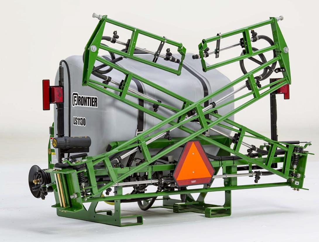
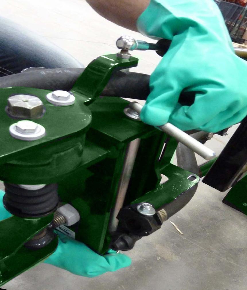
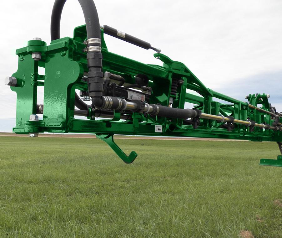
Breakaway Clutch
Each boom is designe d with a breakaway clutch, located betw een the center wing and the main wing sections. The breakaway clutch protec ts the boom from mechanical damage if the boom encounters an obstacle.
Fold Wing Sections
Stop tractor engine, place all controls in neutral, set parking brake, remove ignition key and wait for all moving parts to stop before folding or unfolding the wings.
Wait for spray to stop before approaching sprayer.
Put on PPE as required on the chemical SDS sheet.
Clear area of bystanders. Clear the area of obstacles. Stay away from power lines. Keep away from area between wings when folding to avoid pinch injury.
1.Fold right wing in first.
2.Hold flip wing with both hands. Fold flip wing 180°.
•Hold the wing with both hands until fully folded.
•The flip wing sits over the main wing. The gas shock pulls the flip wing toward the main wing after 90°, then holds wing into place.
3.At the boom pivot remove the hair pin to release the lock pin.
CAUTION: Keep away from area between wings when folding to avoid pinching.
4.Pull the locking pin all the way out.
6.Insert lock pin in the wing pivot through the top and bottom holes.

•Put locking pin in the center hole when wing is folded in.
7.Insert hair pin into locking pin to secure.
8.Repeat process to fold in the left wing. Transport / Storage Position

Unfolding Hydraulic Wings
Stop tractor, place all controls in neutral, set parking brake, wait for all moving parts to stop before folding or unfolding the wings.


Clear area of bystanders. Clear the area of obstacles. Stay away from power lines.
The hydraulic wing sections unfold by pressing the control but ton in the tractor cab. The left and right sides unfold at the same time.
NOTE: The switch controlling the wings depends on how the hydraulic hoses are hooked into the tractor. Normally the pump would be on SCV 1, the Main Wings on SCV 2, and the Swing Wings on SCV 3. Control switches may vary, refer to the tractor manual for instructions.

1.Unfold the Main Wings first. While seated in the operator ’s station, press and hold the hydraulic switch forward to unfold the Main Wings.
2. Unfold the Main Wings until movement stops.
WARNING: Remain alert to hazards, people, or objects in the area surrounding and above the wings as the wing unfolds.
3.Press and hold th e hydraulic switch forward to unfold the Swing Wings.
4.Unfold the Swing Wings until movement stop.
Fold the Hydraulic Wings
The wing sections fo ld by pressing the control button in the tractor cab. The left and right sides fold at the same time.

NOTE: The switch controlling the wings depends on how the hydraulic hoses are hooked into the tractor. Normally the pump would be on SCV 1, the Main Wings on SCV 2, and the Swing Wings on SCV 3.
Control switches may vary, refer to the tractor manual for instructions.

5.Before use, ensure both wings have unfolded fully and are straight.
NOTE: If Swing Wings do not unfold verify that the latch has unlatched.
1.Fold the Swing Wi ngs first. While seated in the operator’s station, press and hold the hydraulic switch back to fold the Swing Wings.
WARNING: Remain alert to hazards, people, or objects in the area surrounding and above the wings as the wing folds.


Controls
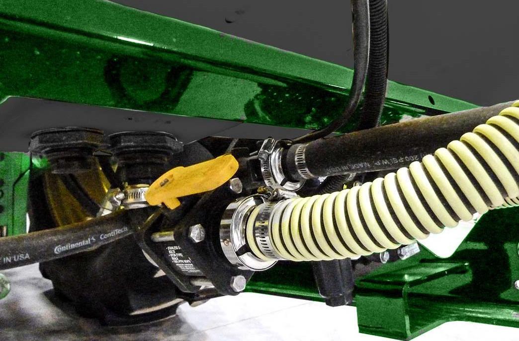
Agitation Pump
The sprayer is equipped with an agitation pump that circulates liq uid in the tank. The circulation maintains constant mixture of chemicals in the tank.
The valve on the agitation pump controls the amount of liquid released to the boom or spray wand.
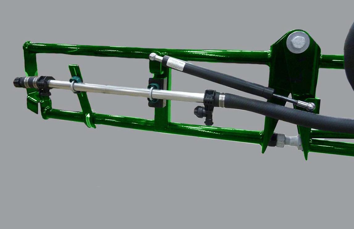
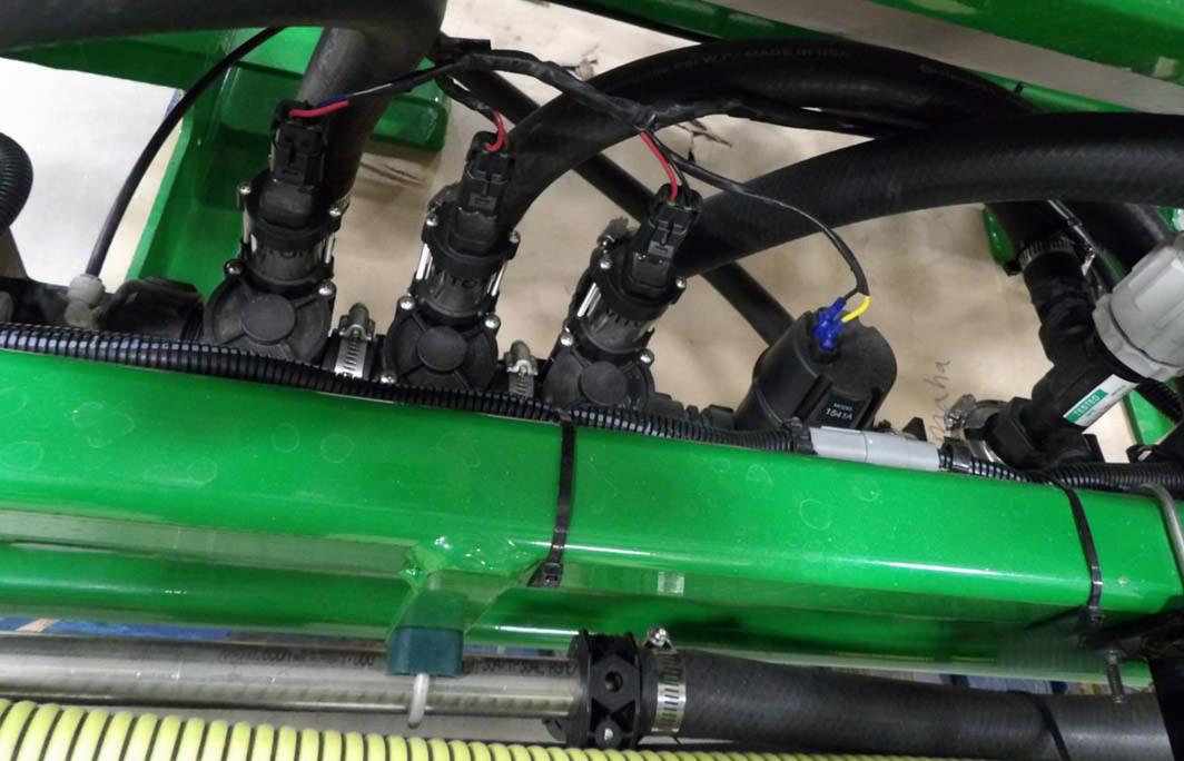
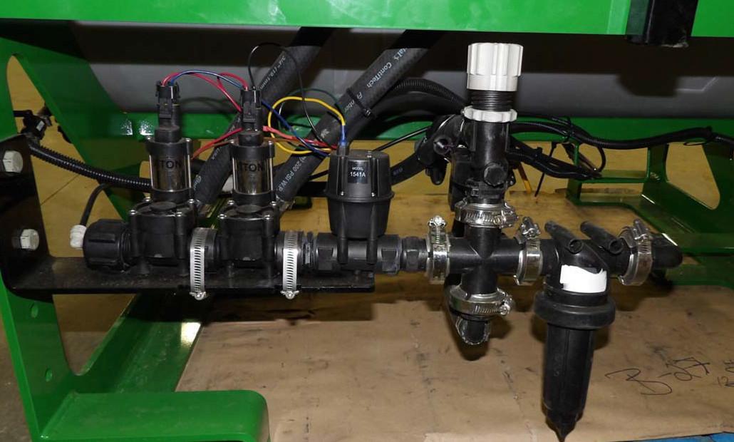
Section Valves
The section valves operate the solution flow to the boom sections. Switches on the valve control box turn the boom sections on or off.
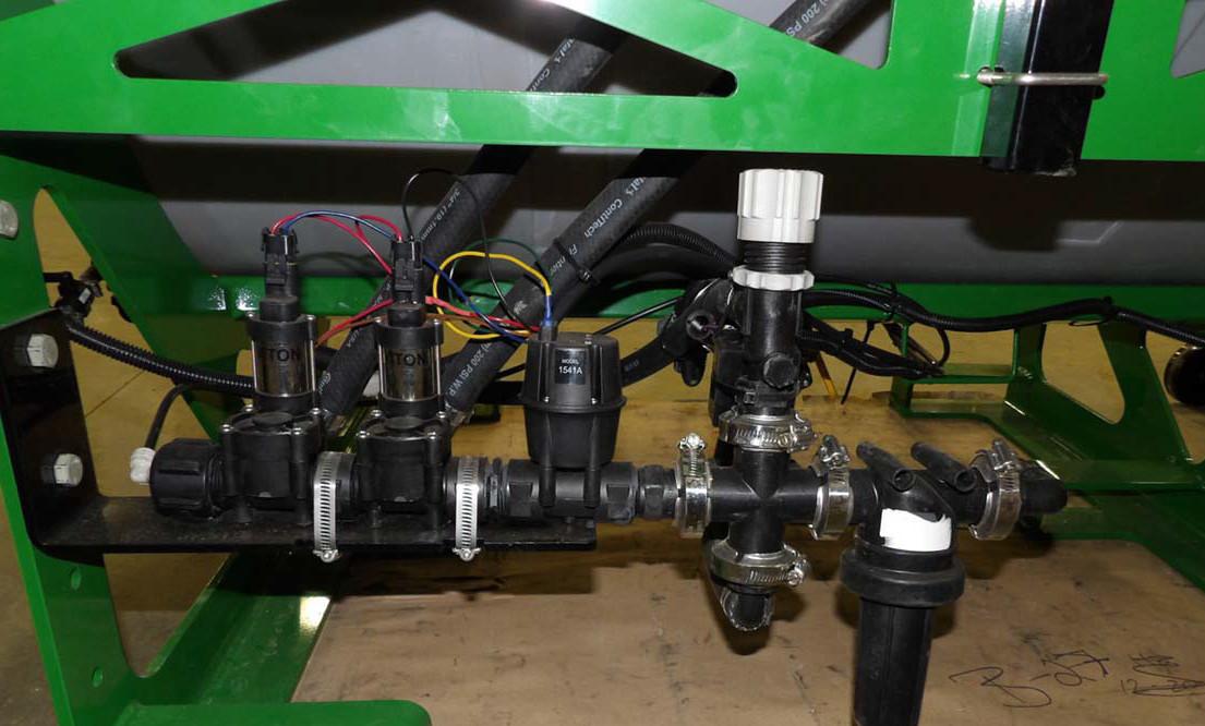
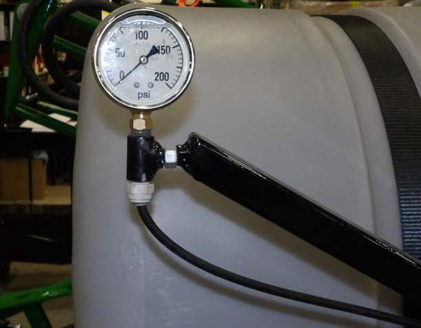
Pressure is monitored on the pressure gauge. Pressure can be adjusted by actuating the pressure swit ch on control pad or by adjusting the agitation valve. The number of valv es vary depending on model size.
l
Partially open the va lve for normal operation.
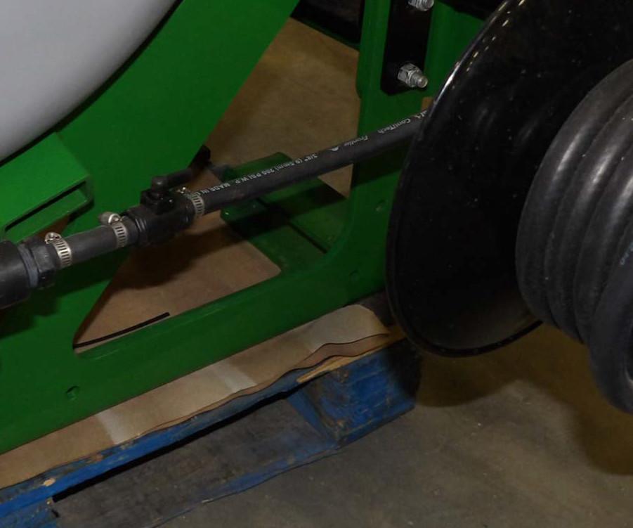
Section valves are mounted below the tank in front of the center boom section.
• Open the valve more to decrease pressure to the booms or spray wand.
•Close the valve more to increase pressure to the booms or spray wand.
1.Master Switch: Switches power to the boom switches. Always use this switch to cut off the entire boom.

2.Boom Switches: Three on-off switches for individual b oom sections.
3.Regulator Switch : Forwards or reverses the regul ator motor which raises or lowers the spraying pressure. Small pressure changes can be made by jogging the switch up or down.

Quick disconnects pe rmit the permanent installation of the control box in the tractor cab.
•Find a convenient place to mount the console. Use the ho les in the mounting bracket as a template to drill holes for mounting screws.
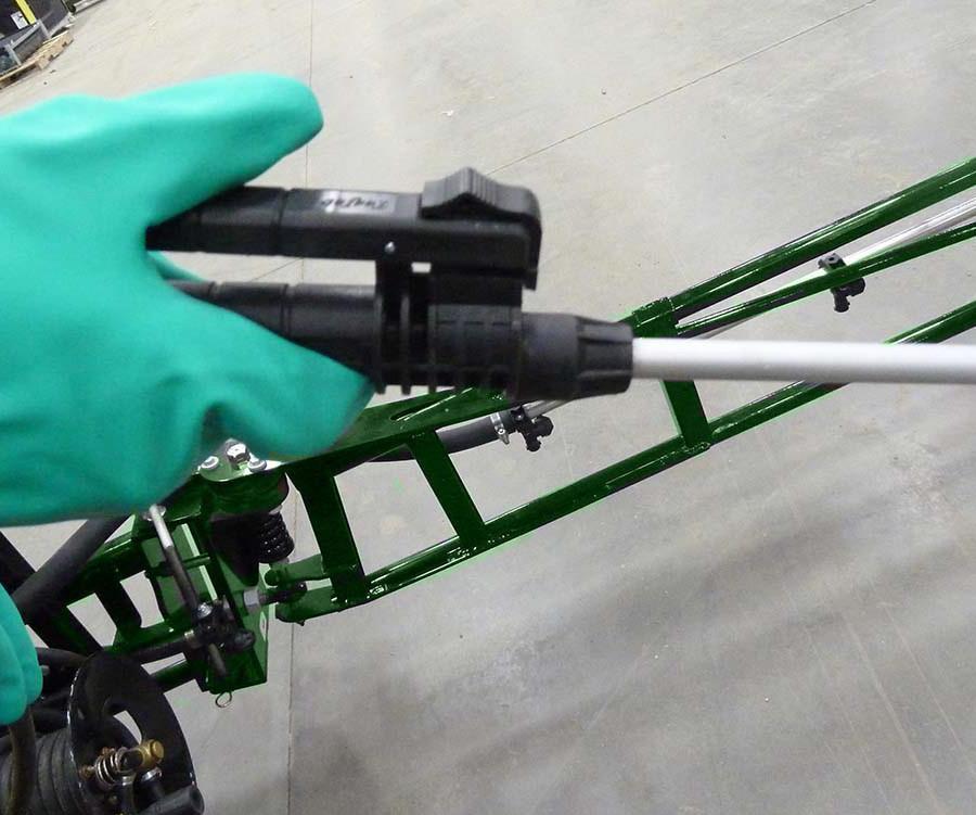
Spray Wand
A wand is provided for use in small areas such as fence lines.
Set parking brake, and wait for all moving parts to stop before using the wand.
Put on PPE as required on the chemical SDS sheet.
Clear area of bystanders.
Do not use the spray wand in windy conditions.
Use caution when locking, unlocking, and winding the hose reel to avoid pinch points.
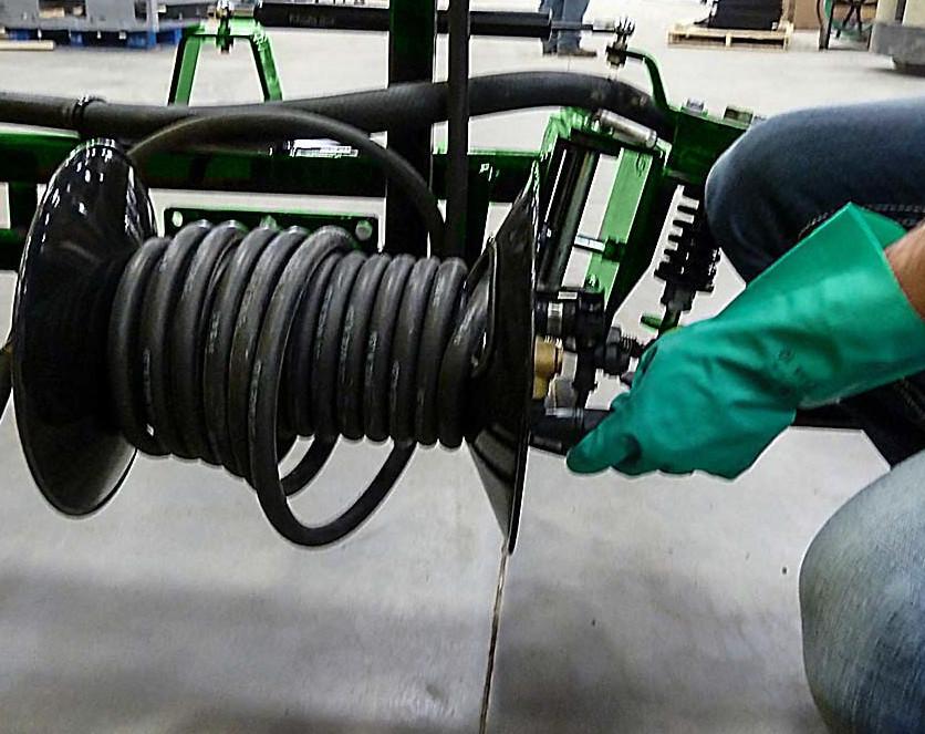
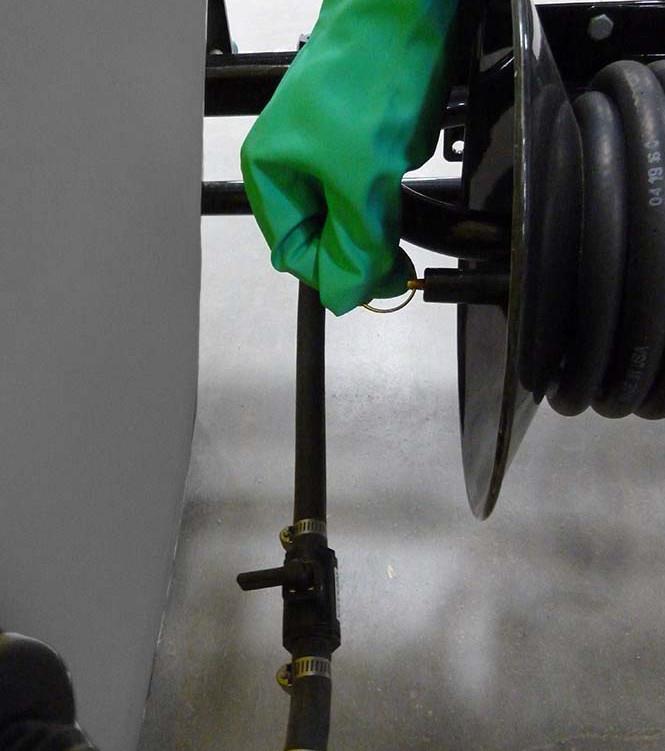
5.Unlock the hose reel.
•Pull and turn pin so ring rests on top of post.
CAUTION: When locking, unlocking, and winding th e hose reel to avoid pinch points.
4.Open tank valve.
•Turn valve handle in line with hose.
6.Release a small amount of hose to loosen the wand.
•Turn handle clockwise to unwind hose.
CAUTION: Use caution removing wand from holder. Keep nozzle pointed away from you at all times.
7.Remove wand from the holder.
9. Open the wand valve.
•Pull up on the wand handle until the wand clears the holder.
•Be careful to keep the nozzle pointed away from you.
8.Set the tank agit ation valve half way between open and closed.
•Turn handle in line with hose
10.Point the wand at the spray target and squeeze the trigger on the wand to spray.

•Close the valve more to increase pressure to wand.
•Open the valve more to decrease pressure to wand.
IMPORTANT: Do not fully close the agitation valve while operating the wand. Excess pressure may damage chemical pump and spray wand.
•Pull hose from the reel as needed to reach area to be sprayed.
11.Release wand tri gger to stop spray.
12.Close the wand valve when finished spraying.
14.Wind up the hose.
•Turn handle 90° from solution line.
Caution: When locking, unlocking, and winding the hose reel avoid pinch points.

13.Return wand to holder.
•Turn reel handle counter clockwise to wind up hose.

15.Lock the hose reel pin.
•Feed nozzle of hose wand into holder and slowly slide wand in.
•Pull pin out slightly, turn until ring falls into detent.
16.Turn off the chemical pump.
17.Close tank valve if finished spraying.
•Turn tank valve handle 90° from hose line.
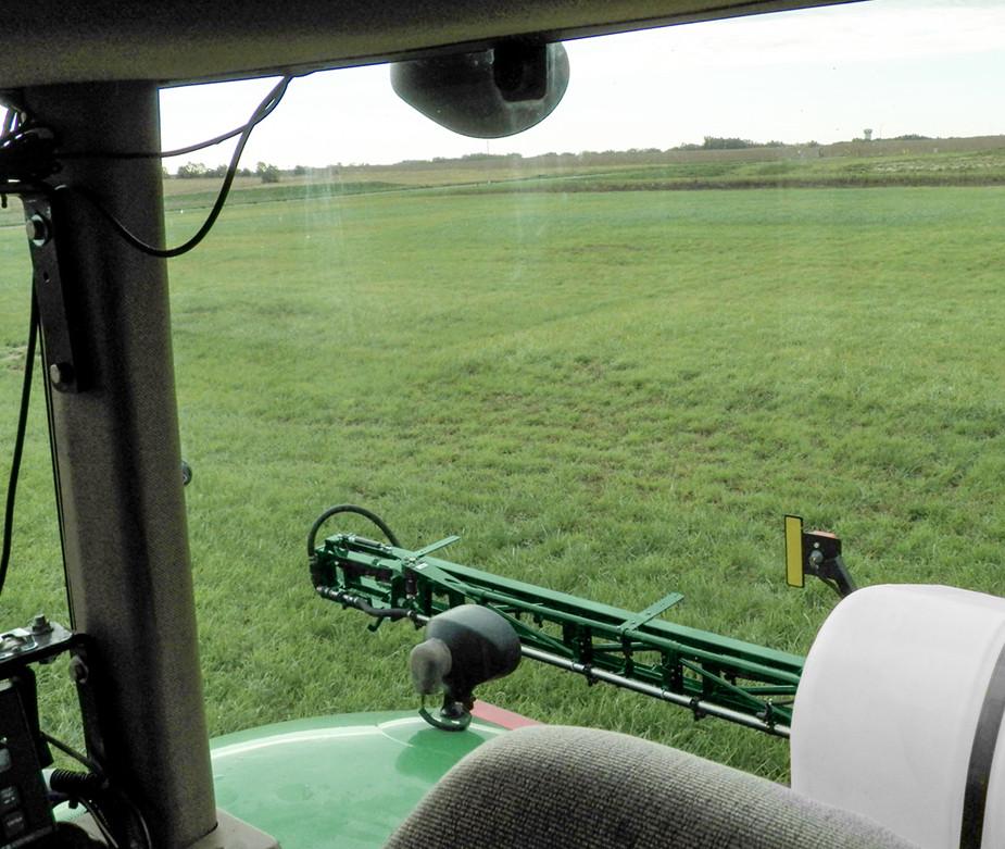
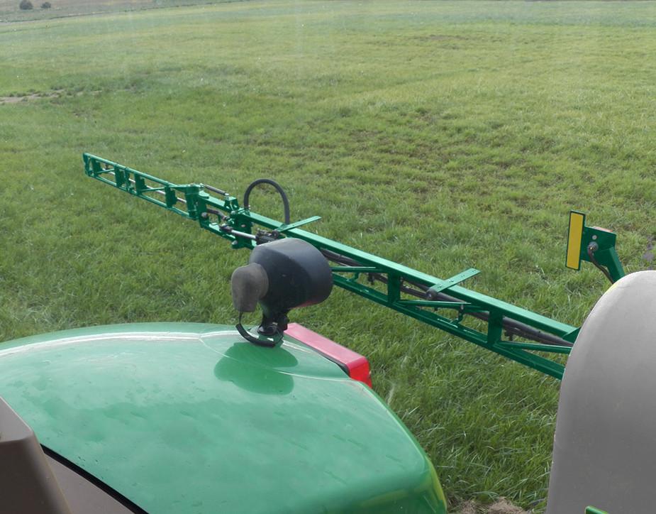
Foam Marker Operation
Do not attempt to operate machine without covers in place.
Never operate machine while unattended.
Inspect machine fo r damage after use.
Never allow children to operate this machine.
Wear safety goggles and all proper clothing when operating, servicing or refilling this machine.
Chemical mist or liquid can cause permanent eye, skin or lung damage or death.
Always read and follow manufacturer recommendations when handling any chemical.
Never operate this product in or near explosive atmospheres or where aerosol products are being used.
Do not use air compressor to pump anything other than atmospheric air.
Do not pump combustible liquids or vapors with this product or use in or near an area where flammable, explosive liquids, or vapors may exist.
Do not use this product near flames.
Mixing Foam
Foam mixing takes so me experience. Different water sources may require different amounts of concentra te to obtain the desired foam density. Water hardness, pH, and impurities will all affect the rate of concentrate required for a consistent, longlasting foam.
Different conditions may require different mixing ratios to produc e desirable results. It is worthwhile to determine the proper foam/water mixing ra tios for your water source with the initia l filling. Doing so will save time in the future and aid in consistent foam quality.
If hard water is a problem, commercial softening agents are available. You can make your own softening agent by dissolving a commercial wate r softening powder (available in most grocery stores) in hot water and adding a porti on of this mixture to your tank each time you fill . Experimentation will reveal t he correct amount to use. A good starting point is 1 1/2 ounces per gallon of water.
Mix ratios for foam concentrates advertised as 80:1 or 160:1 must be adjusted for use with your water, such ratios are only a guideline.
Heat, humidity, wind and crop cover will also affect the life of foam. Using a good quality marking agent, such as Enduron PSI™ Marking Foam -PM65201, may be very important.
Compressor Check
After checking all wiring for accuracy, flip the switch to the “o n” position and check that air is flowing out of the compressor.
Filling The Tank
Wear safety goggles and all proper clothing when operating, servicing or refilling this machine. Always read and follow manufacturers recommendations when handling any chemical.
Do not pump combustible liquids or vapors with this product.
1.BE SURE POWER UNIT IS TURNED OFF. Remove the c ap from the top of the tank.
2.Starting with a sm all amount of water (2 gal), mix the foam concentrate according to the label directions. If con- siderably more concentrate is needed above the manufacturer’s suggested ratio (usually 2-5 ounces per gallon) to produce good foam, use of a softener or soft water may be required. If the foam is too stiff (dry), it may surge out at irregular intervals. Under this condition, water should be added until the foam becomes more wet.
3.To ensure proper mixing of foam concentrate and water, you may find it necessary to partially fill the tank, add the foam concentrate, then completely fill the tank.
4.Replace cap at th e top of the tank.
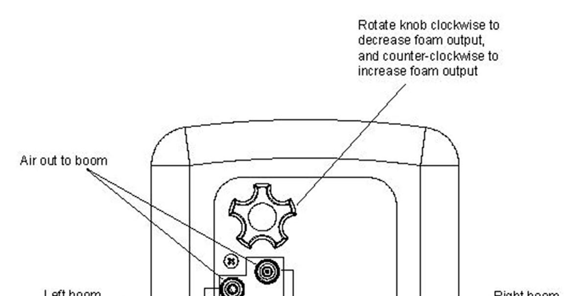
FLOW CONTROL VALVE / TUBING CONNECTIONS
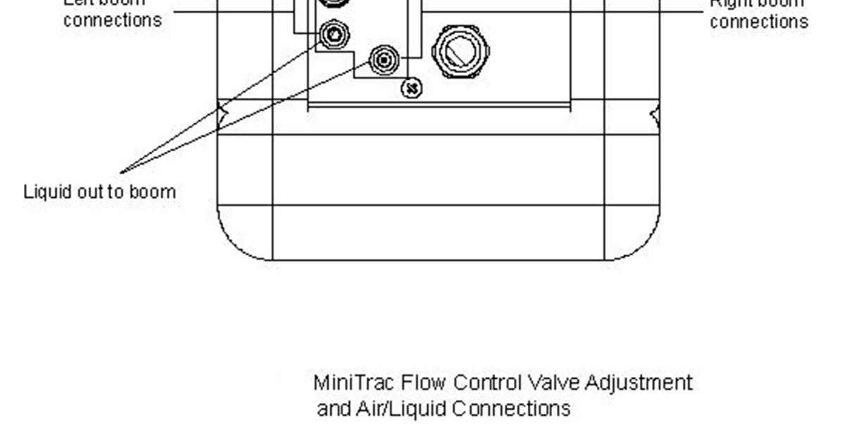
The flow control valve regulat es the amount of foam solution flowing to the foamheads. To increase liquid flow, turn the adjusting knob counter-clo ckwise. This valve has been factory preset at ½ turn open. This setting provides for a moderate foam output.
Maintenance And Service Lubrication
Understand service procedures before doing work.
Keep service area clean and dry.
Never lubricate, se rvice or adjust machine while it is moving. Keep hands, feet and clothing from power driven parts.
Lower equipment to the ground.
Disengage all power.
Relieve hydraulic pressure before serving or disconnecting from tractor.
Securely support all machine elements that must be raised for service work. Use tools, jacks, and hoists of sufficient capacity for the job.
Clear area of bystanders when making adjustments, filling, servicing or repairing the equipment.
Use adequate lighting for the job.
Keep all parts in good condition and properly installed. Fix damaged immediately.
Replace worn and broken parts. Remove any buildup of grease, oil, or debris.
Disconnect wiring harness from tractor before servicing electrical system components or welding on machine.
Remove paint and any residue from solvents before welding or heating.
Use caution to avoid pinch points.
Wear appropriate PPE for the area of the machine you are working.
Grease: Use an SAE multi-purpose high temperature grease with extreme pressure (EP) performance. An SAE multi-purpose lithium base grease is also acceptable.
Use a hand held grease gun.
Clean fittings bef ore greasing.
If a fitting will not take grease, remove and clean thoroughly, clean and lubricate the passageway. Replace fitting if necessary.
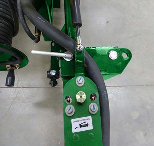
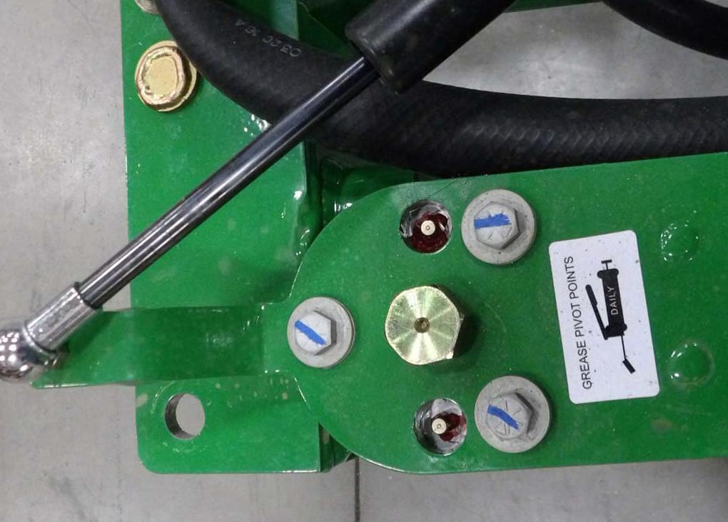
Grease Points
Wing Pivots
•Grease the wing pivots daily.
Breakaway Clutch
•Grease fittings daily.
Pump Maintenance And Service
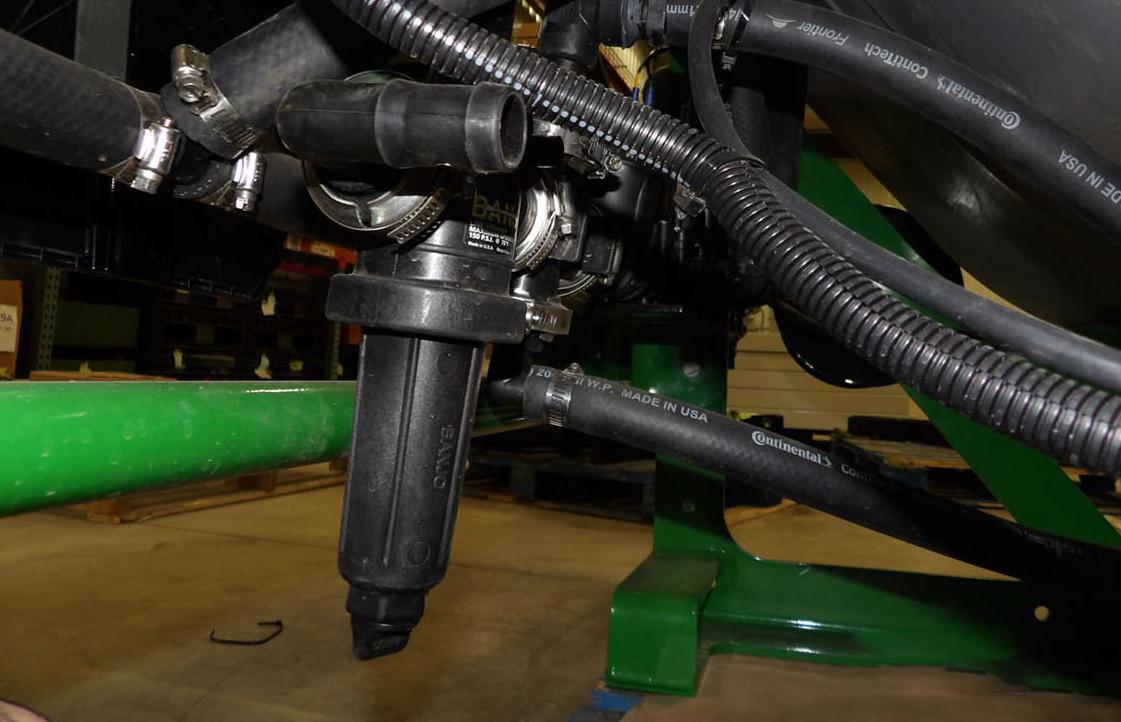
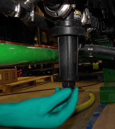
Filter Cleaning
The filter location va ries by operating system. There may be more than one filter. Follow the procedure below for each filter.
At the start of each day before the water and chemicals have been added, the screens should be checked and cleaned.
Filter
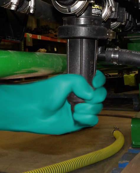
IMPORTANT: Loosen and tighten the filter bodies by hand. Do not use a wrench as this could damage the filter body.
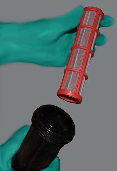
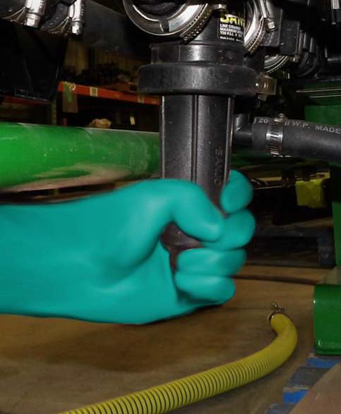
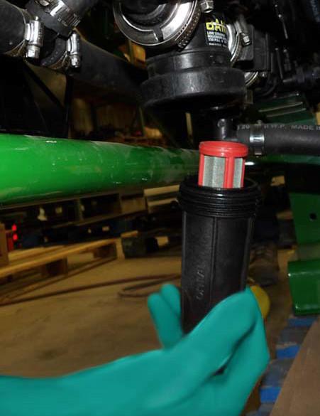
3.Turn the filter body to remove.
4.Remove screens and inspect for dirt or damage.
5.Clean screens using clean water.
6.Inspect screen for holes or tears. If screen is damaged replace it.
7.Place the screen back into the filter body.
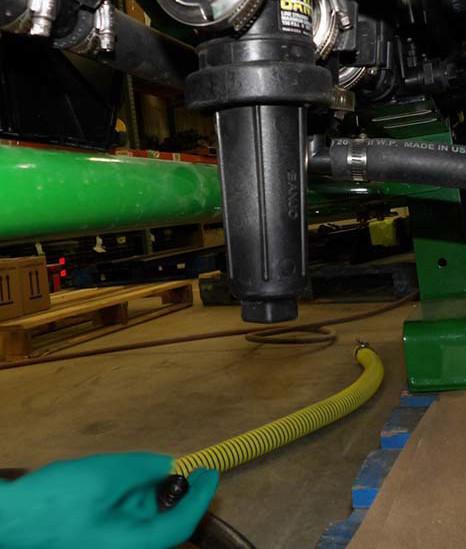
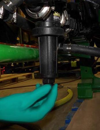
9.Reinstall the drain plug.
8. Install the screen and body to the filter heads and tighten by hand. Do not over tighten and crack the head.
NOTE: Remove drain plug and drain screens before storage to avoid freezing.

Boom Maintenance And Service
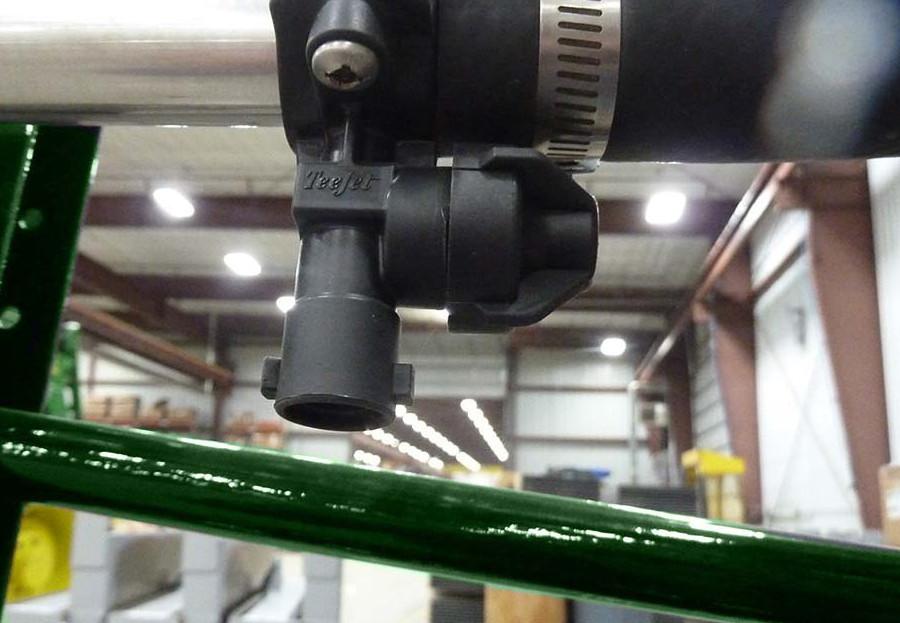
Nozzles
Clean nozzles weekly, before changing chemicals and before calibrating.
Wing Bumpers
Single Spray Nozzle
1.Remove nozzle housing and remove nozzle tip.
2.Clean nozzle tip with clean water.
3.Reinstall nozzle tip.
4.Install nozzle housing and hand tighten.
Tighten boom clamps
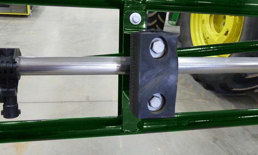
1.Inspect wing bumpers for wear and damage.
2.Replace bumpers as when worn or damaged.
•Remove both bolts
•Remove damaged bumper
•Install new bumper
•Replace bolts and tighten.
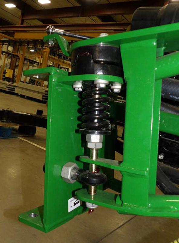
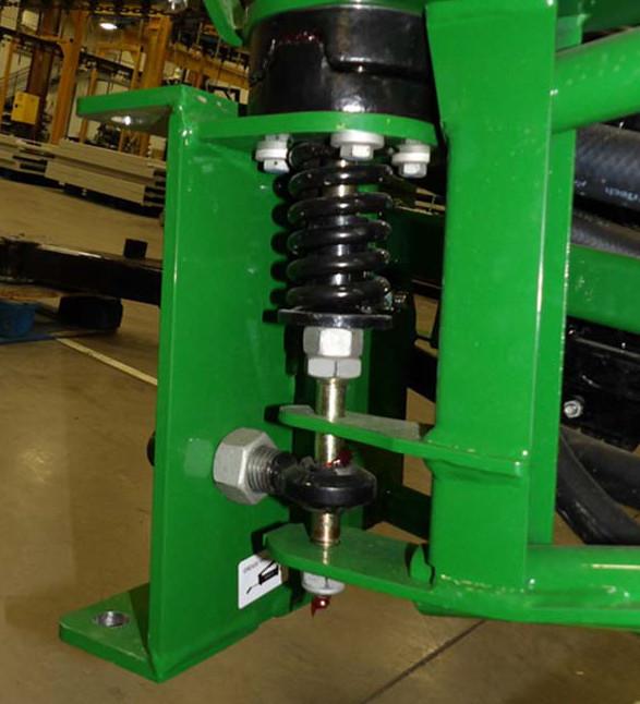
Gas Shocks
The gas shocks between wing sections are designed to limit movement of the wing section when fo lded or unfolded.
When folding or unfolding the flip wing section you should feel the gas shock pull or snap the section in to place. The flip wing section should be stable in the field or transport position. If not replace the gas shock.
When unfolding or folding the main wing section you should feel resistance and the wing should be stable in the field position. If the main wing wobbles, breaks position easily, or slams hard into position it may be necessary to replace gas shock.
•Test operation.
To replace gas shock:
•Remove the nut holding the shock to the frame.
•Repeat on other end of the shock.
Tank Maintenance And Service
Read the chemical manufactures warnings and follow instructions exactly.
Put on the PPE required on the chemical SDS sheet.
Clear bystanders from the area. Know your working location and how to seek medical attention in an emergency.
Never put your head or body into the tank.
Stop tractor engine, place all controls in neutral, set parking brake, remove ignition key and wait for all moving parts to stop before cleaning tank.
Tank Drain Procedure
Follow this procedure to completely drain the tank.
1.Spray as much liquid through the booms as possible.
2.Place a pail under the tank valve.
3.Close the tank valve
4.Disconnect the hose from the outlet end of the tank va lve and allow the hose to completely drain into the pail
•Turn valve handle 90° from hose line.
•Loosen clamp
•Carefully remove hose from fitting.
•Drain hose into a pail.
5.Slowly open the t ank valve and allow the tank to completely drain.
6.Once draining is co mplete, close tank valve, reconnect the hose to the outlet end of the tank valve.
7.Tighten clamp.
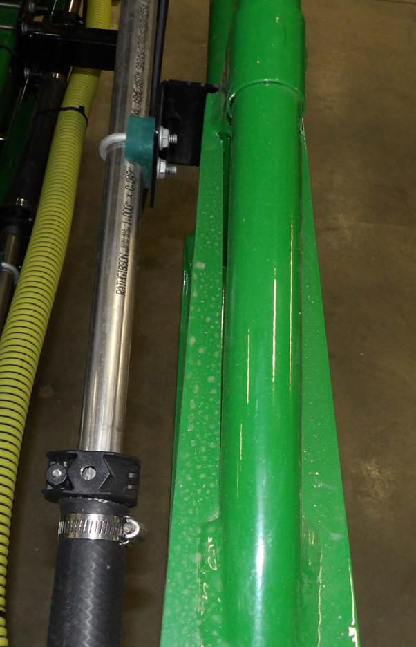
Tank Straps
Tighten the bolt on the strap buckles until the straps have just started to depress the top of the tank. The buckle should not be tight against the cradle frame.
Daily Cleaning
At the end of the working day, clean the system using this procedure:
1.After the chemical solution has been completely spraye d out through the booms, add 20 gallons (75 liters) clear water to the tank.
2.Run the agitation pump for 5 minutes.
3.Spray the rinse lightly over previously sprayed crop.
4.Clean the screen and nozzles.
5.Drain tank and let dry.
Cleaning to Remove Salt and Amines Formations
Perform this cleaning cycle with changing chemicals and/or annually:
1.Follow the procedure for daily cleaning.
2.Remove screens and nozzles and wash separately.
3.Add 50 gallons (200 liters) of clean water to the tank.
4.Add 1/2 gallon (2 liters) of household ammonia to the tank. (1-part ammonia to 100 parts water).
5.Run the agitation pump for 5 minutes.
6.Spray half the solution out of the booms.
7.Let the balance sit for a minimum of 8 hours, overnight is best.
8.Run agitation pump for 10 minutes.
9.Spray solutions out of booms on the appropriate crop.
10.Rinse the system thoroughly with clean water and flush out the booms.
11.Drain the entire system and let dry.
Cleaning to Remove Esters of 2, 4-D and MCPA Formations
Perform this cleaning cycle when changing chemicals or annually:
1.Follow the procedure for daily cleaning.
2.Remove nozzles and screens and wash separately.
3.Add 50 gallons (200 liters) clean water to the tank.
4.Add dishwasher detergent to the tank (2 lbs/ 50 gal or 1kg/300 l of water).
5.Run agitation pump for 10 minutes.
6.Spray the solution out of the booms on appropriate crop and drain thoroughly.
7.Add 50 gal (200 L) of clean water to tank.
8.Add 1/2 gal (2 L) of household ammonia to the tank (1-part ammonia to 100 parts water).
9.Run agitation pump for 10 minutes.
10.Spray 1/2 the solution out of the booms.
11.Let the balance sit for a minimum of 8 hours, overnight is best.
12.Run the agitation pump for 10 minutes.
13.Spray out of the booms on the appropriate crop.
14.Rinse the system thoroughly with clean water and flush out the booms.
15.Drain entire system and let dry.
Replace Pressure Gauge
Replace the pressure gauge and or pressure line if damage d or malfunctioning.
Tail Light Replacement
Disconnect main wiring harness from tractor.
To replace pressure gauge:
•Relieve pressure to the booms.
•Uninstall the pressure gauge by loosening the mounting nut. (Item 1)
•Replace gauge and tighten nut.
To replace pressure line hose:
Disconnect the tail light wiring harness (1).
•Relieve pressure to the booms.
•Disconnect the pressure line from gauge. (Item 2)
•Disconnect pressure line from section valves. (Item 3)
•Replace hose, be sure to route hose through support bracket. (Item 4)
•Reconnect hose to gauge.
•Reconnect hose to section valves.
•Test operation.
To replace bulb:
• Twist socket (2) to remove light.
•Replace bulb.
•Insert socket into light assembly. and twist to lock.

•Connect tail light wiring harness (1).
To replace broke light:
•Remove broken light socket (2).
•Remove light assembly bolts (3).
•Replace light assembly.
•Install bolts (3).
•Install light socket (2).
•Connect tail light wiring harness (1).