17 minute read
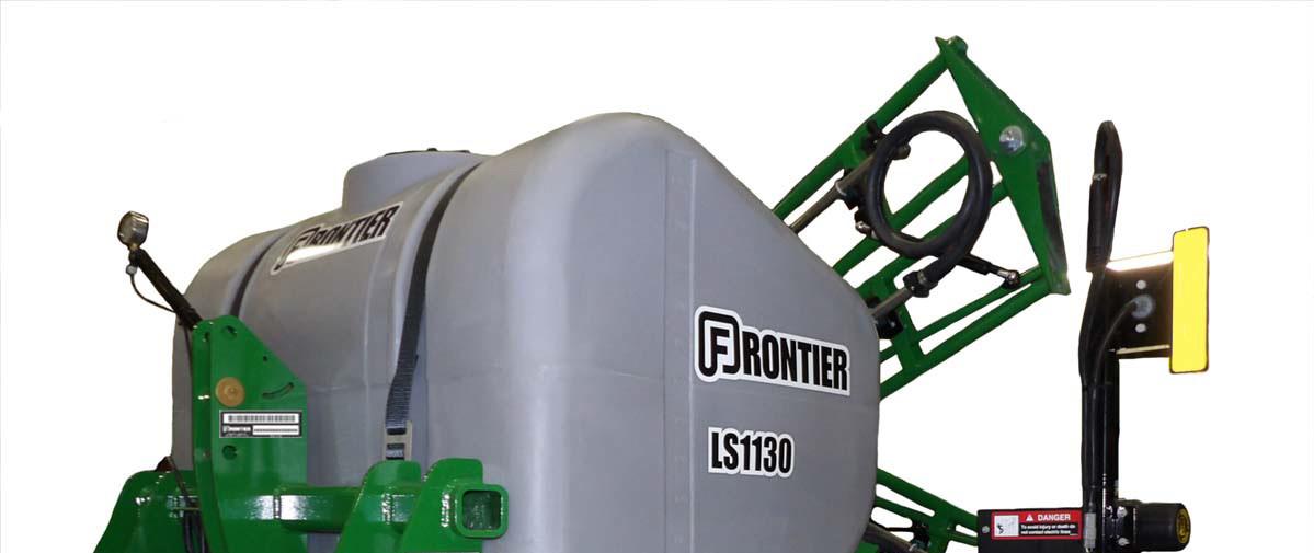
MOUNTED LIQUID SPRAYER


Ls11 Delivery Inspection Checklist
Dealers should complete this check sheet upon equipment delivery.
Date: _____________________
Model: ____________________________
Serial Number:______________________
Inspected by: _______________________
Look over unit for any damage that may have occurred during shipping.
Verify the unit configuration to th e sales order to ensure no parts have been removed or changed.
Verify that all hardware is tight.
Verify that all plumbing con nections are tight. Leave any disconnected product hoses disconnected until pre-delivery preparations are completed.
Verify the tail lights are in working order.
Remove this page from the manual and retain for your records.
This page intentionally left blank.
This page intentionally left blank.
Introduction
Read this manual carefully before operating your Frontier equipment. The information presented will prepare you to safely operate and service your machine. Require all operators to read this manual carefully and be acquainted with all the operating and adjustment procedures before attempting to operate. Failure to follow the information in this manual and on decals may result in personal injury or equipment damage.
This manual should be considered a permanent part of this equipment and should remain with the equipment when you sell it. Replacement manuals can be obtained from your John Deere dealer.
This equipment has been engineered and manufactured to provide dependable and satisfactory use. Like all mechanical products, it will require cleaning and upkeep. Inspect your equipment before putting it into service. Your authorized John Deere dealer has trained mechanics, genuine John Deere service parts, and the necessary tools and equipment when service is needed. Use only genuine John Deere parts for service or repairs. Substitute parts will void the warranty and may not meet standards for safe and satisfactory operation.
Warranty is provided as part of John Deere’s support program for customers who operate and maintain their equipment as described in this manual. The warranty is explained on the warranty certificate you should have received from your dealer. This warranty provides you with the assurance that John Deere will back its products where defects appear within the warranty period. Should the equipment be abused, or modified to change its performance beyond the original factory specifications, the warranty will become void.
These instructions have been compiled from field experience and engineering data. Some information may be general in nature, due to unknown and varying operating conditions. However, through experience and these instructions, you should be able to develop procedures suitable to your particular situation.
The illustrations and data used in this manual were current at the time of printing. However, due to possible in-line production changes, your machine may vary slightly in detail. We reserve the right to redesign and change the machines as may be necessary without notification.
Throughout the manual references are made to right and left direction. These are determined by standing behind the equipment facing the direction of forward travel.
Equipment Identification
The equipment serial number is located on the serial tag or serial plate attached to the main frame.
See “SAFETY AND INSTRUCTIONAL LABELS” on page8.

Write the equipment serial number below. Use the serial number when ordering parts and service.
We recommend that you also file the model and serial number in a secure place off the machine.
MODEL___________________________ SERIAL NUMBER___________________ PURCHASE DATE
Safety
The most important safety devise on this equipment is a safe operator. It is the operator’s responsibility to read and understand and follow all safety and operating instructions in this manual.
As the operator, you are responsible for the safe operation and maintenance of this equipment. You must ensure that you and anyone else who is going to operate, maintain or work around the machine is familiar with the operating and maintenance procedures and related safety information contained in this manual.
You are the key to safety. Good safety practices protect you and people around you. Be certain that everyone operating this equipment is familiar with the recommended operating and maintenance procedures and follows all safety precautions. Do not risk injury or death by ignoring good safety practices.
Safety Alert Symbols and Signal Words
Throughout this manual, the terms Caution, Warning, and Danger are used along with the safety alert symbol to indicate the degree personal safe ty hazard. The term Important is used to indicate that failure to observe can cause damage to the equipment.
Safety Alert Symbol
A SAFETY ALERT SYMBOL means there is a hazard. Become Alert! Your Safety is Involved!
Danger
The word DANGER indicates an imminently hazardous situation that, if not avoided, will result in death or serious injury.
Warning
The word WARNING indicates a potentially hazardous situation that, if not avoided, could result in death or serious injury.
Caution
The word CAUTION indicates a potentially hazardous situation that if not avoided may result in minor or moderate injury.
Important
The word IMPORTANT indicates that failure to observe can cause damage to equipment.
Note
The word NOTE indicates helpful information.
General Safety
Carefully read and follow all safety messages in this manual and safety signs (decals) on equipment.

A safety sign may contain more than one hazard message and more than one avoidance panel.
Learn how to operate the machine and how to use the controls properly. Do not let anyone operate the machine without instruction.
Keep the machine in proper working condition. Unauthorized modifications to the machine may impair the function and/or safety and affect machine life.
Do not operate or transport this machine while under the influence of alcohol or drugs. Consult your doctor about operating this machine while taking prescription medications.
If you do not understand any part of this manual and need assistance, contact your John Deere dealer.
Prepare for Emergencies
Keep a fire extinguisher and first aid kit handy. Know how to use them.
Keep emergency numbers for doctors, ambulance service, hospital, and fire department near your telephone.
Keep the Poison Control emergency telephone number for your area on sprayer before using chemicals.
Have the chemical container and SDS available when seeking medical attention.
Personal Protection Equipment (PPE)
Wear close fitting clothing and safety equipment appropriate for the job.
Wear the appropriate protective clothing and devices as described on the chemical SDS sheet.
Handle Chemicals Safely
Direct exposure to hazardous chemicals can cause serious injury.
A Safety Data Sheet (SDS) (formerly Material Safety Data Sheet (MSDS)) provides specific details on chemical products: physical and health hazards, safety procedures, and emergency response techniques. Read the chemical manufacturers warning, instructions and procedures before starting and follow them exactly.
Potentially hazardous chemicals are used with John Deere equipment include such items as lubricants, coolants, paints, and adhesives.
Check the SDS before you start any job using a hazardous chemical. That way you will know exactly what the risks are and how to do the job safely. Then follow procedures and recommended equipment.
Keep Riders Off Machine
Do not allow riders on the sprayer or the tractor during operation or transport.
Riders are subject to injury from being struck by foreign objects, exposure to chemicals, and being thrown off the machine.
Riders obstruct the operator’s view resulting in the machine being operated in an unsafe way.
Riders are subject to exposure to chemicals as they are being applied which could create a health hazard.
Maintenance Safety
Understand service procedures before starting work.
Keep service area clean and dry.
Never lubricate, service or adjust machine while it is moving. Keep hands, feet and clothing from power-driven parts.
Lower equipment to the ground.
Disengage all power.
Relieve hydraulic pressure before serving or disconnecting from the tractor.
Stop the engine. Remove the key. Allow the machine to cool.
Securely support all machine elements that must be raised for service work. Use tools, jacks, and hoists of sufficient capacity for the job.
Clear area of bystanders when making adjustments, filling, servicing or repairing the equipment.
Use adequate lighting for the job.
Keep all parts in good condition and properly installed. Fix damaged components immediately. Replace worn and broken parts.
Remove any build-up of grease, oil, or debris.
On towed implements, disconnect the wiring harness from the tractor before servicing electrical system components or welding on machine.
Remove paint and any residue from solvents before welding or heating.
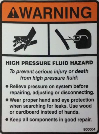
Hydraulic Safety
The hydraulic system operates under extremely high pressure. Escaping fluid under pressure can penetrate the skin causing serious injury.
If an accident occurs, seek medical assistance immediately. DO NOT DELAY. Any fluid injected into the skin must be surgically removed. Serious infection or toxic reaction can develop from hydraulic fluid piercing skin surface.
Doctors unfamiliar with the is type of injury should reference a knowledgeable medical source. Such information is available from Deere & Company Medical Department in Moline, Illinois, USA.
Avoid the hazard by relieving pressure before disconnecting hydraulic or other lines.
Tighten all connections before applying pressure.
Replace worn, cut, abraded, flattened or crimped hoses.
Do not attempt makeshift repairs to hydraulic lines, fittings or hoses by using tape, clamps or cements.
Check for leaks with a piece of cardboard, Do Not use your hands to check for leaks. Protect hands and body from high-pressure fluids.
Avoid Heating Near Pressurized Fluid Lines
Flammable spray can be generated by heating near pressurized fluid lines, resulting in severe burns to yourself or bystanders.
Do not heat by welding, soldering, or using a torch near pressurized fluid lines or other flammable materials. Pressurized lines can be accidentally cut when heat goes beyond the immediate flame area.
Waste Disposal Safety
Improper disposal of waste can threaten the environment and ecology. Potentially harmful waste used with John Deere equipment includes oil, coolant, brake fluid, filters, and batteries.
Use leak-proof containers when draining fluids. Do not use food or beverage containers that may mislead someone into drinking from them.
Do not pour waste onto the ground, down a drain, or into any water source.
Follow instructions on chemical containers or SDS sheets for disposal of chemicals, containers, and water used for cleaning the equipment.
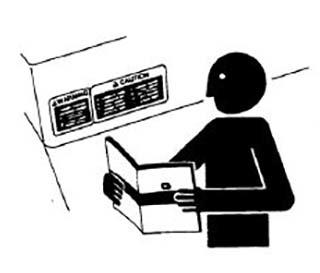
Safety Signs (Decals)
Keep safety signs in good condition.
Replace missing or damaged safety signs.
Be sure new equipment components and repair parts include the current safety signs.
Replacement signs are available from your John Deere dealer.
Storage Safety
Store equipment away from human activity.
Do not allow children to play on or around the stored machine.
Empty and clean out the chemical tank before storing.
Lower the machine and securely block.
Transportation Safety
Obey all applicable laws and regulations for transporting equipment.
Verify that the chemical tank is empty before transporting on roadways.
Do not allow riders.
Do not exceed 20 mph (32 km/h) when transporting.
Use caution on inclines, curves, when making turns and adverse road conditions.
Be sure sprayer is properly connected to the towing vehicle and a retainer is used.
Always engage the safety locks on the hitch.
Booms must be folded into transport position when transporting.
Reduce speed on rough terrain and on slopes.
Stopping distance increases with speed, weight, and on slopes.
When transporting on roadways frequently check for traffic from the rear, especially in turns, and use turn signal lights.
Use headlights, flashing warning lights, and turn signals day and night.
Keep lighting, reflectors, and markings visible, clean and in good working order.
Repair or replace lighting and markings that have been damaged or lost.
Do not operate or transport the equipment while under the influence of alcohol or drugs. Consult your doctor about operating this machine while taking prescription medications.
Operation Safety
Read and understand this Operator’s Manual and all safety signs before using.
This sprayer is intended to be used ONLY on vehicles with an enclosed, pressurized operator station.
Before each use inspect the entire machine. Check tightness of nuts and bolt and fittings.
Lower machine to the ground, stop the tractor engine and remove key, set parking brake, and wait until all moving parts have stopped before leaving the operator’s compartment to adjust, lubricate, clean or unplug the machine.
Keep hands, feet, hair, and clothing away from all moving parts.
Do not allow riders on the sprayer or tractor.
Make sure everyone is clear of the machine before filling sprayer tank, starting tractor engine or beginning operation.
Read chemical or fertilizer manufacturers warnings, instructions, and procedures before starting and follow them exactly.
Do not breathe, touch or ingest chemicals or fertilizers. Always wear protective clothing and follow safe handling procedures.
Keep bystanders away when unfolding or folding wings.
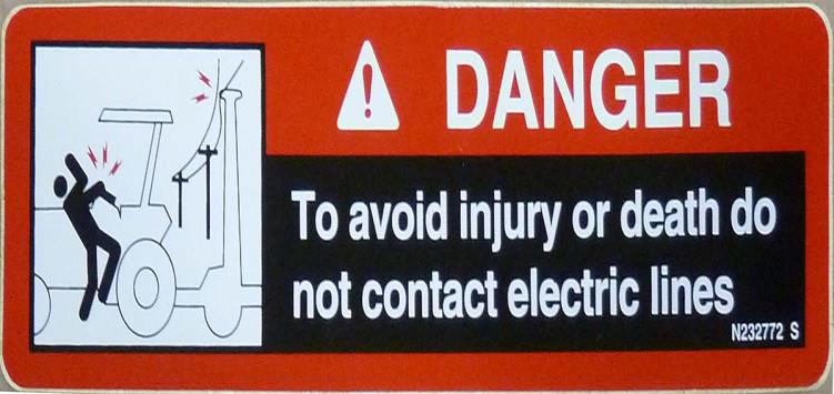
Stay away from overhead power lines when folding or unfolding wings.
Keep clear of wings when unfolding or folding. Avoid pinch points.
Install and secure all guards and shields. Always operate the machine at rated speed.
Drive slowly over rough ground.
Safety And Instructional Labels

ATTENTION! BECOME ALERT! YOUR SAFETY IS INVOLVED!
FAILURE TO FOLLOW THESE INSTRUCTIONS COULD RESULT IN SERIOUS INJURY OR DEATH!
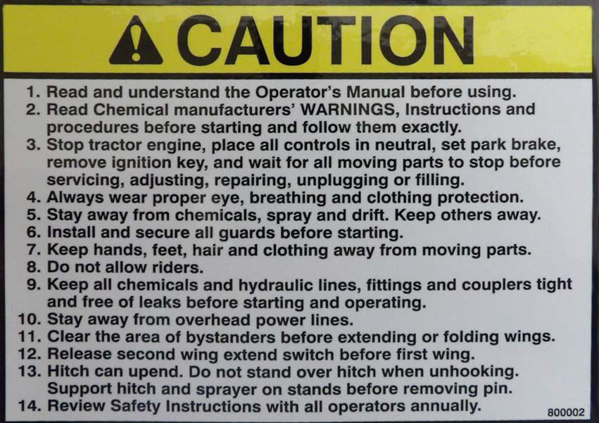

REPLACE LABELS IMMEDIATELY IF DAMAGED!
Lights And Reflectors
ATTENTION! BECOME ALERT! YOUR SAFETY IS INVOLVED!
FAILURE TO FOLLOW THESE INSTRUCTIONS COULD RESULT IN SERIOUS INJURY OR DEATH!
REPLACE LIGHTS AND REFLECTOR S IMMEDIATELY IF DAMAGED!


Chemical Safety
ATTENTION! BECOME ALERT! YOUR SAFETY IS INVOLVED!
FAILURE TO FOLLOW THESE INSTRUCTIONS COULD RESULT IN SERIOUS INJURY OR DEATH!
REPLACE LABELS IMMEDIATELY IF DAMAGED!
This equipment is designed for the spray application of chemicals.
Read chemical manufacturer s’ warnings, instructions and procedures before starting and follow them exactly.
Wear protective clothing including but not limited to gloves, eye protection, and breathing mask.
This sprayer is intended to be used ONLY on vehicles with an enclosed, pressurized operator station.
Always carry the SDS shee t of the chemical being used on the sprayer.
Be alert and use caution when folding or unfolding wings, filling tank, setting chemical pumps and servicing to avoid chem ical spills, drips, and vapors.
Spray only when the potential fo r chemical drift is at a minimum. Even small amounts can affect neighboring crops, sensitive plants, and people.
Do not eat while using this equipment.
Wash hands and arms thoroughly before eating. Use a detergent to remove chemical residue. Rinse carefully and dr y with disposable towels.
Store this equipment away from children and livestock.
Always follow instructions for the chemical being used.
Post Poison Control Emergency tele phone number for your area on sprayer. Washington DC: (202) 962-4525 Ottawa: ( 613) 992-5606
Have SDS and chemical cont ainer label available when seeking medical attention.
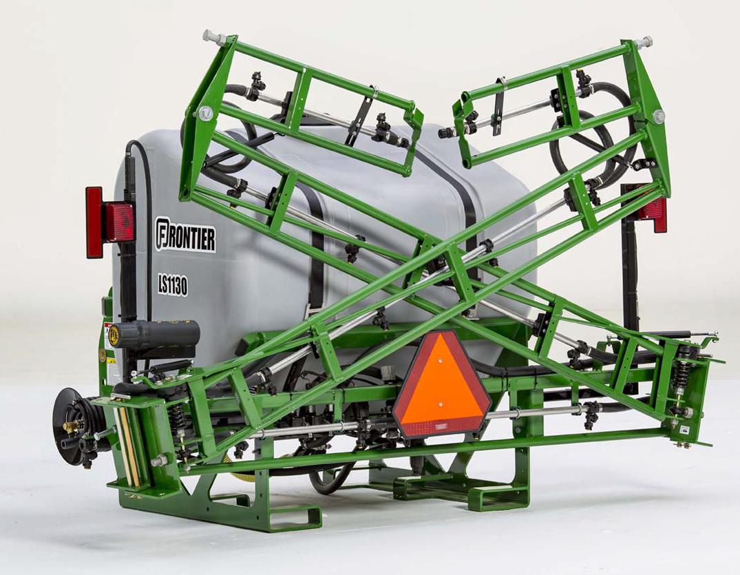
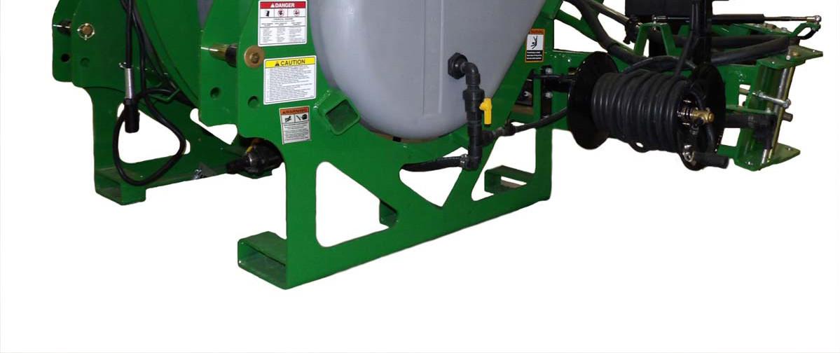
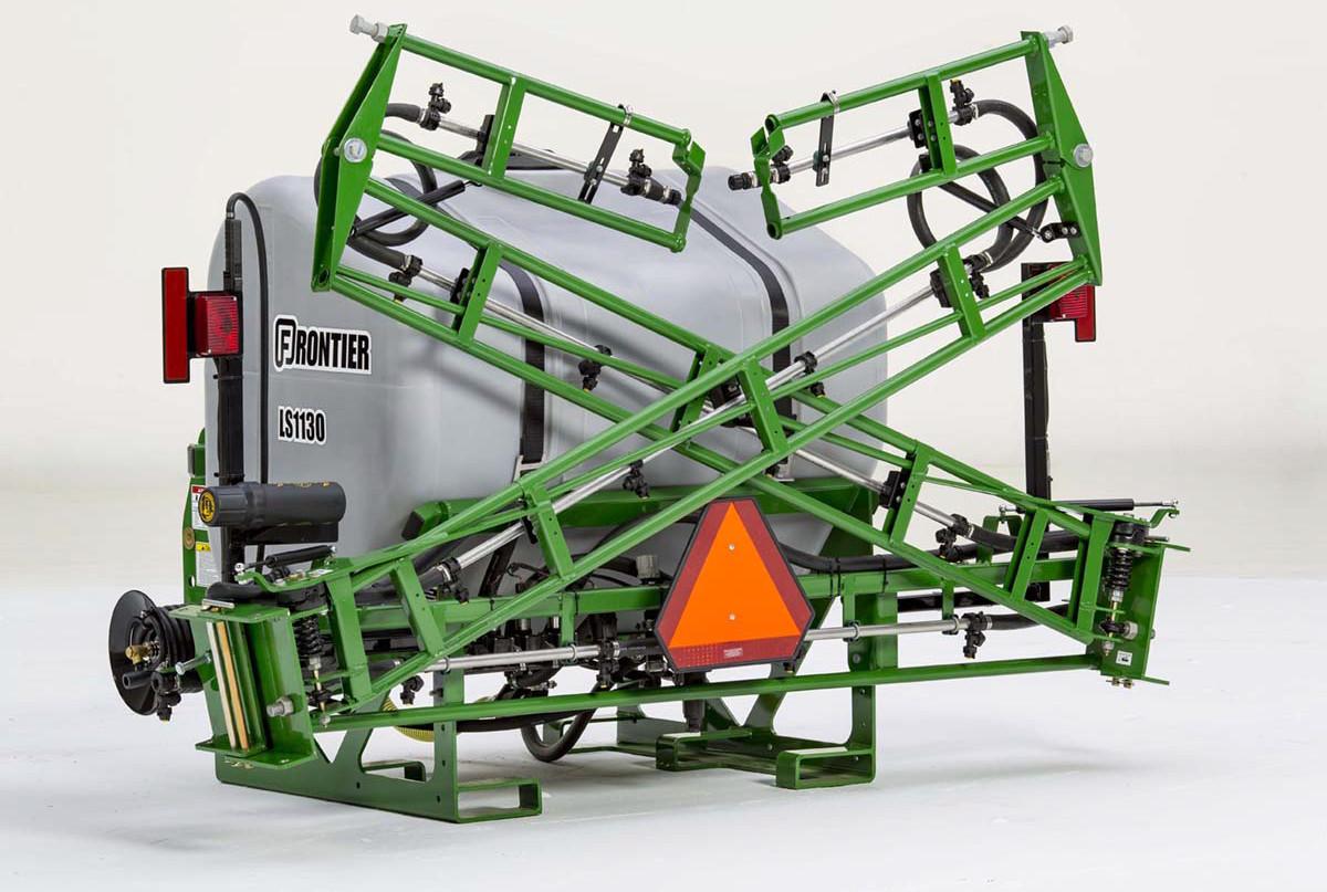
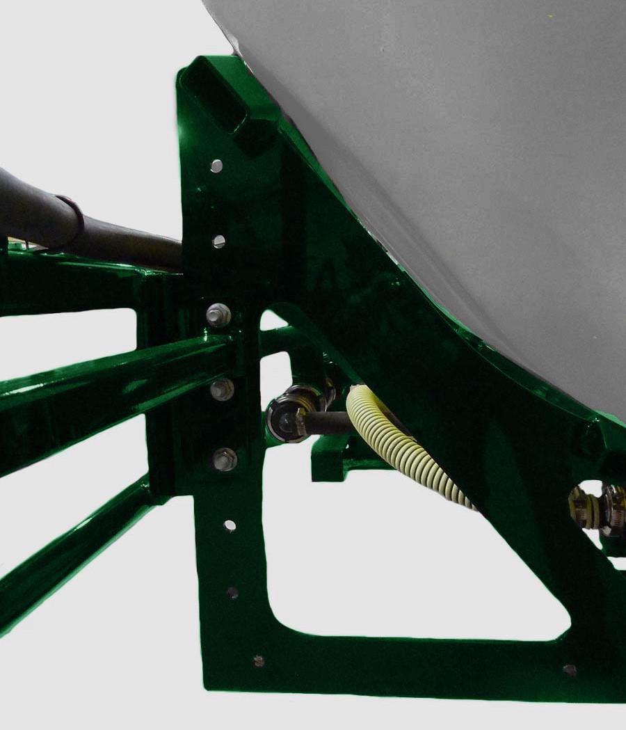
Major Components
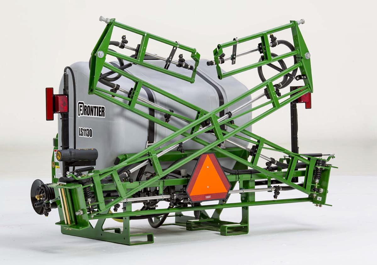
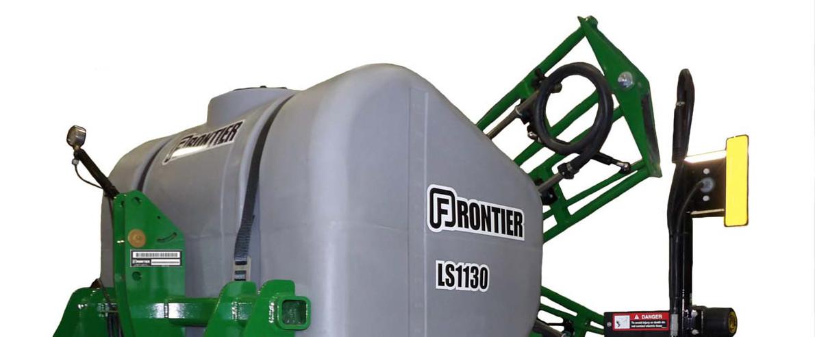
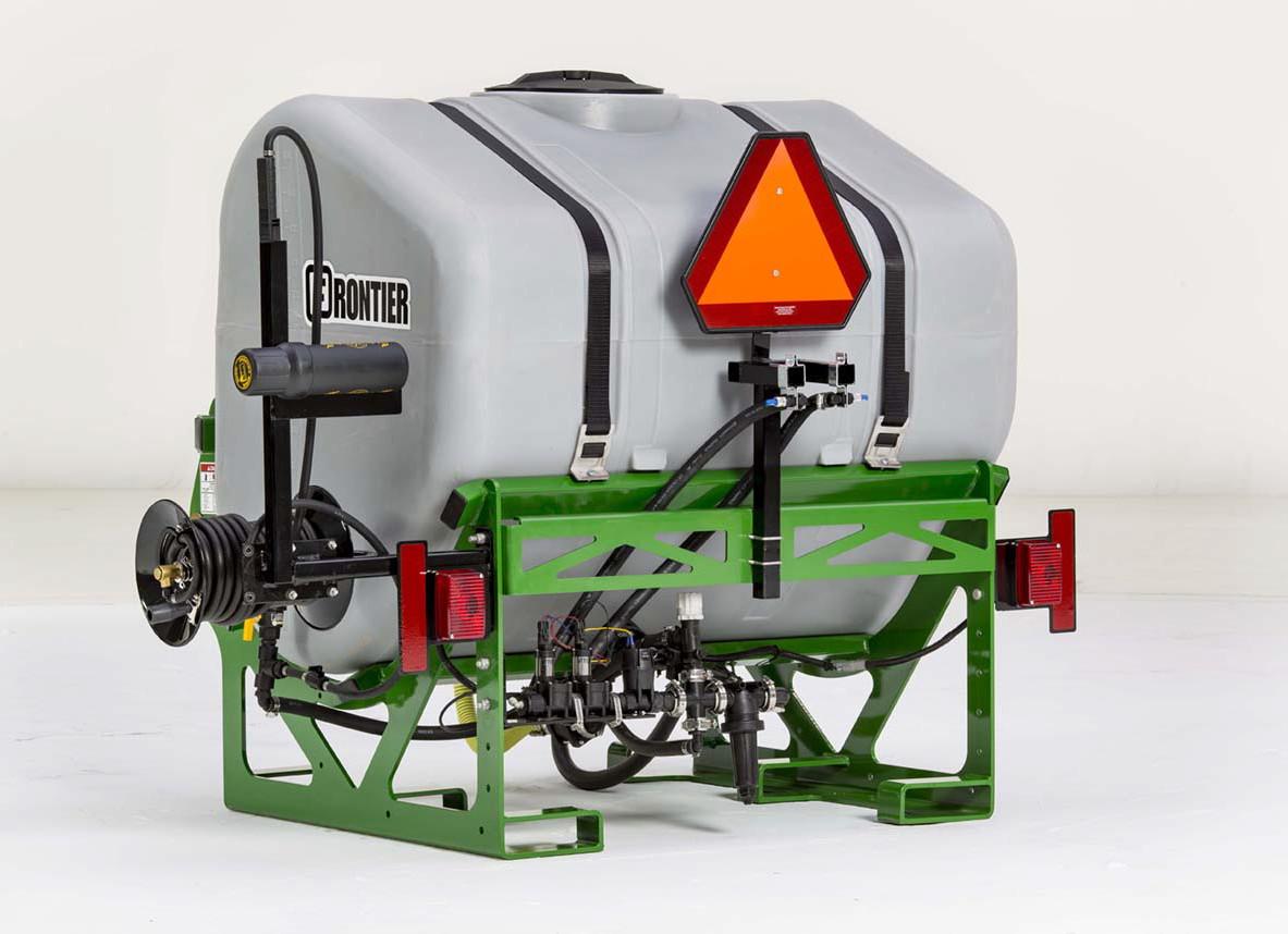
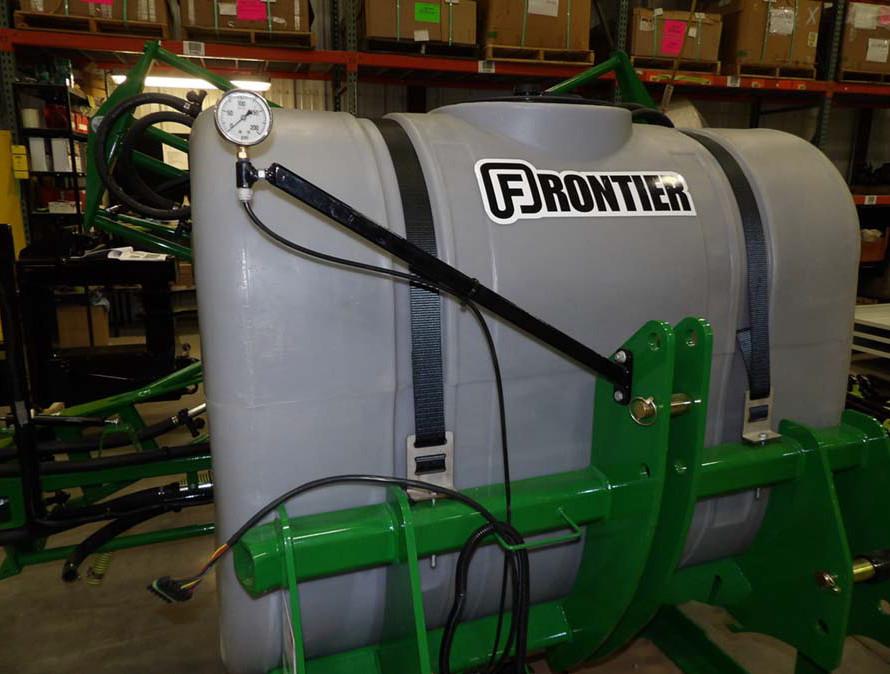

Preparing Machine Assembly
Upon arrival the spraye r will require initial assembly. This will typically be completed by a Frontier Dealer.
Drain and Rinse the Tank
The sprayer is shipped with a small amount of RV antifreeze in the tank. The tank must be drained and rinsed before use.
Drain Filters
1.Place a pail under filter.
2.Remove the drain plug from the filter.
3.Allow to drain.
4.Replace plug.
5.Repeat for addi tional filters. See “PUMP MAINTENANCE AND SERVICE” on page54.
Drain Tank
1.Locate the tank drain below the tank.
2.Place a pail or c ontainer under drain.
3.Disconnect the fittin g from the tank.
4.Allow fluid to drain.
5.Reinstall hose fitting.
6.Add 10 gallons of water to the tank.
7.Disconnect the fittin g from the tank.
8.Allow rinse to drain.
9.Reinstall hose fi tting and tighten.
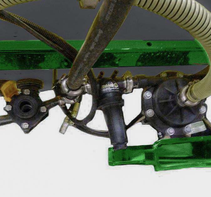
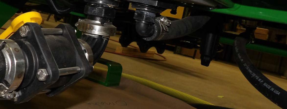
Connect PTO Pump
When the sprayer is operated with a PTO Pump the hoses will need to be connected.
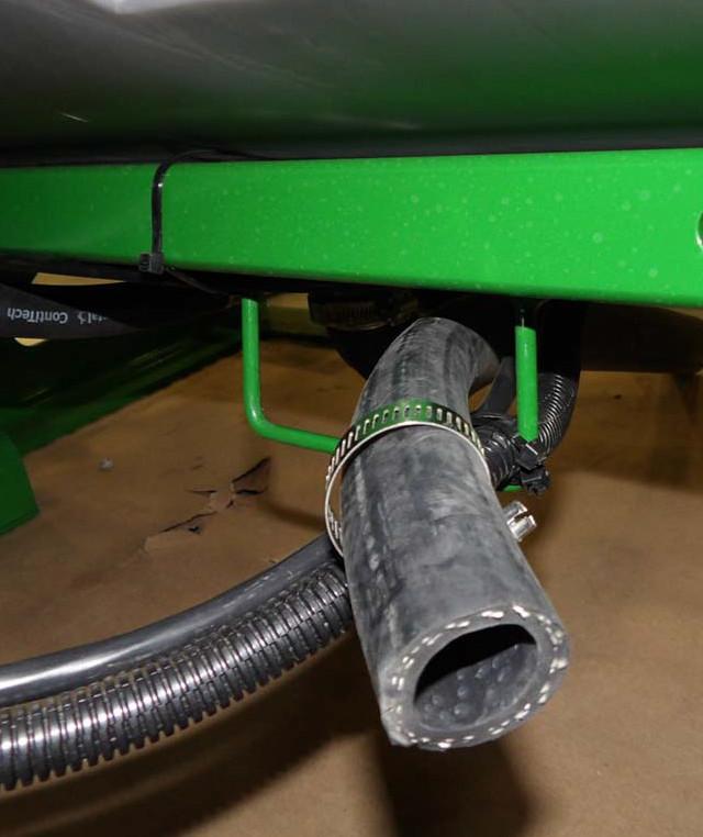
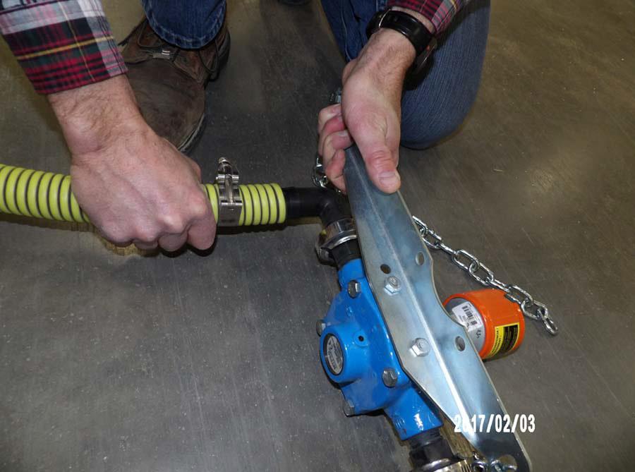
1.The hoses are zip tied to the center boom for shipping. Cli p the zip ties to release hoses.
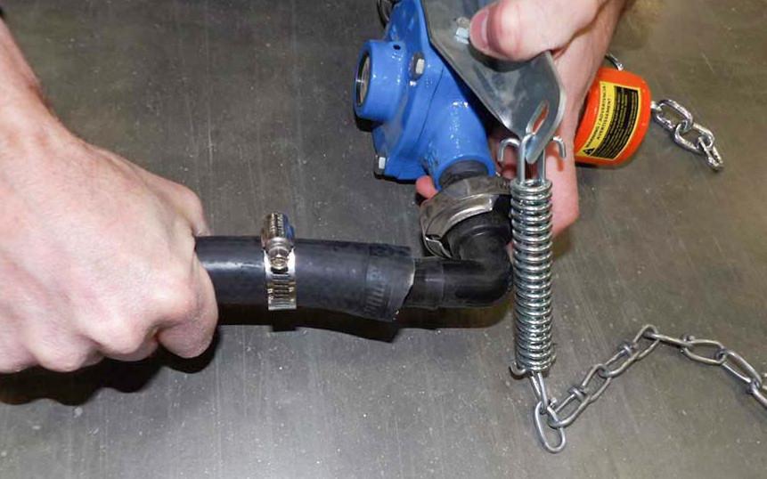
4.Attach the 1” black hose to the outlet side of the PTO pump.
•Loosen clamp.
•Slide hose onto right side fitting on PTO.
•Tighten clamp
2.Attach the 1.25” yellow hose to the inlet side of the PTO pump.
•Loosen clamp and slide hose onto the left PTO fitting.
•Tighten clamp.
3.Attach hose to sprayer.
•Loosen clamp.
•Slide hose onto pu mp fitting.
•Tighten clamp.
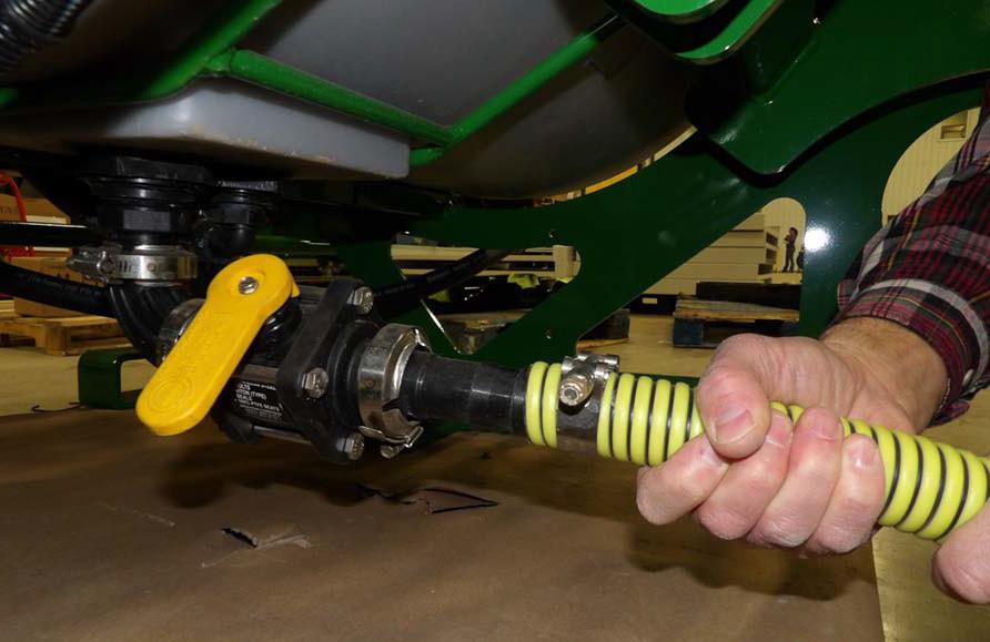
5.Route hose under tank and through support on main frame.
6.Attach hose to section valves.
•Loosen the clamp.
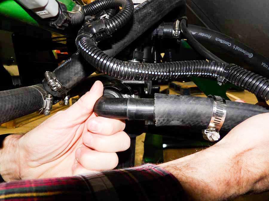
•Slide the hose onto the section valve fitting. Use one hand to support the fitting as shown.
•Tighten clamp.
7.Attach the sprayer to the tractor. See “ATTACH SPRAYER TO TRACTOR” on page25.
8.Connect the PTO pump. If the hoses are too long:
•Disconnect PTO pump from tractor.
•Disconnect hoses from PTO pump.
•Cut hoses to size needed to fit tractor.
•Reconnect hoses to PTO pump.
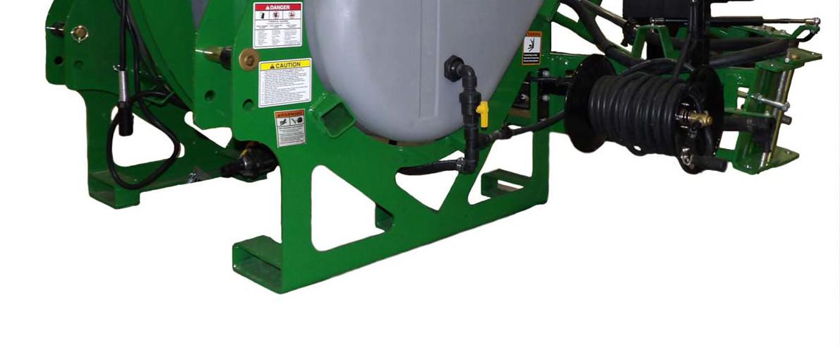
Spray Wand
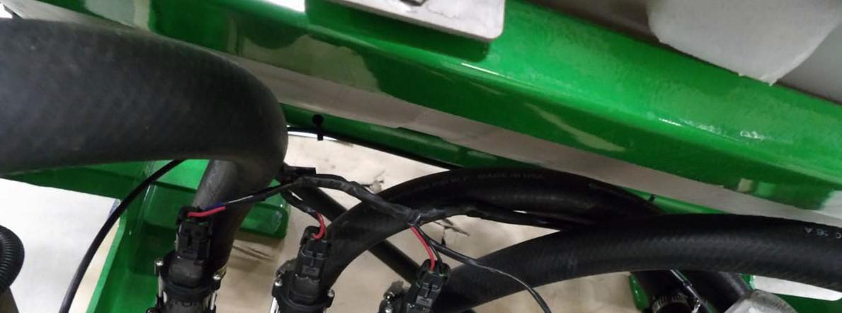
The spray wand is zip tied to the spray wand holder for shipping. Carefully cut the ties to release.
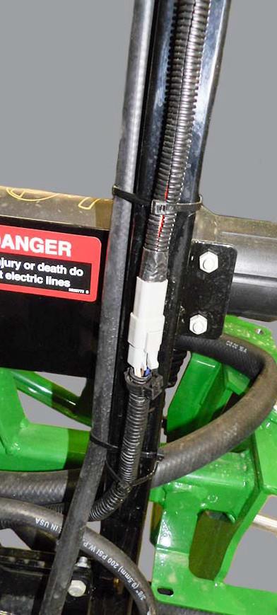
NOTE: The electrical harness for the tail light is also zi p tied to the spray wand holder. Only cut the ties holding the spray wand hose.
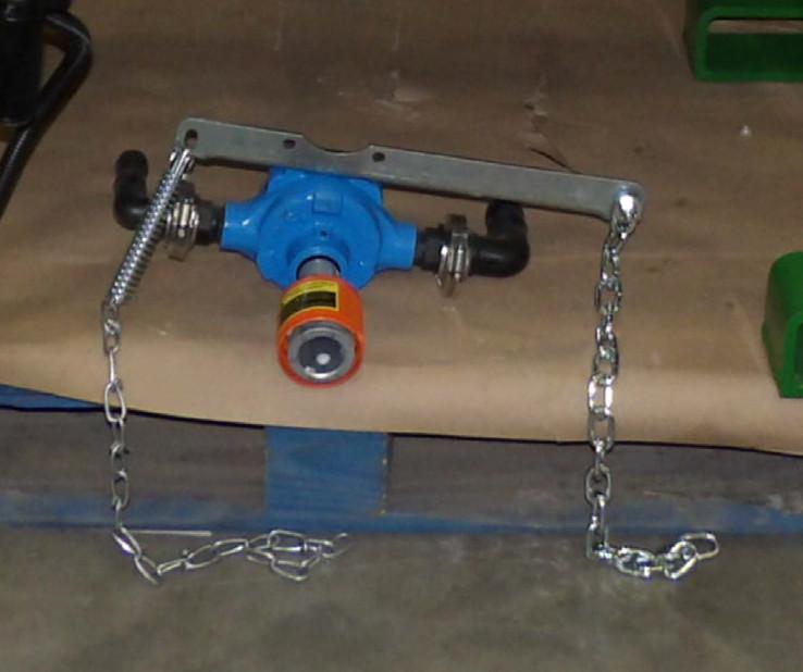
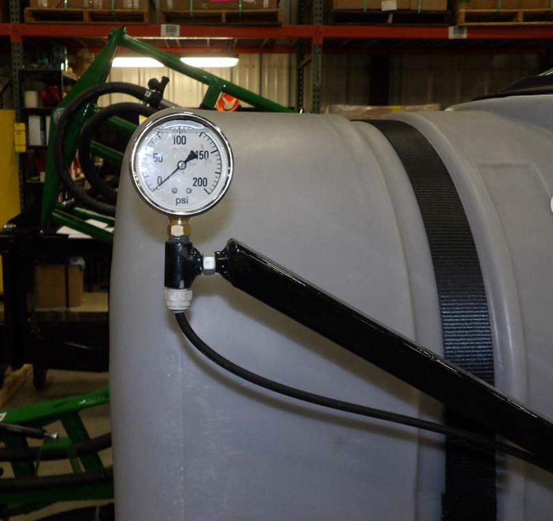
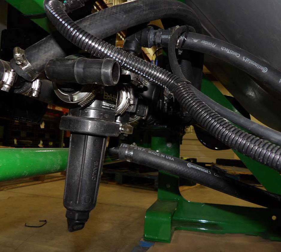
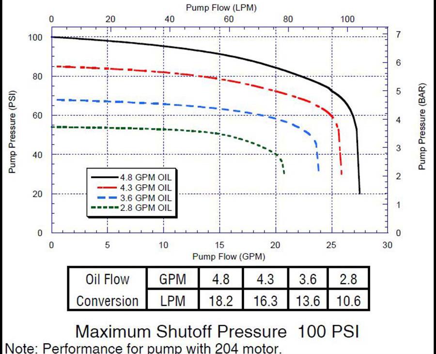
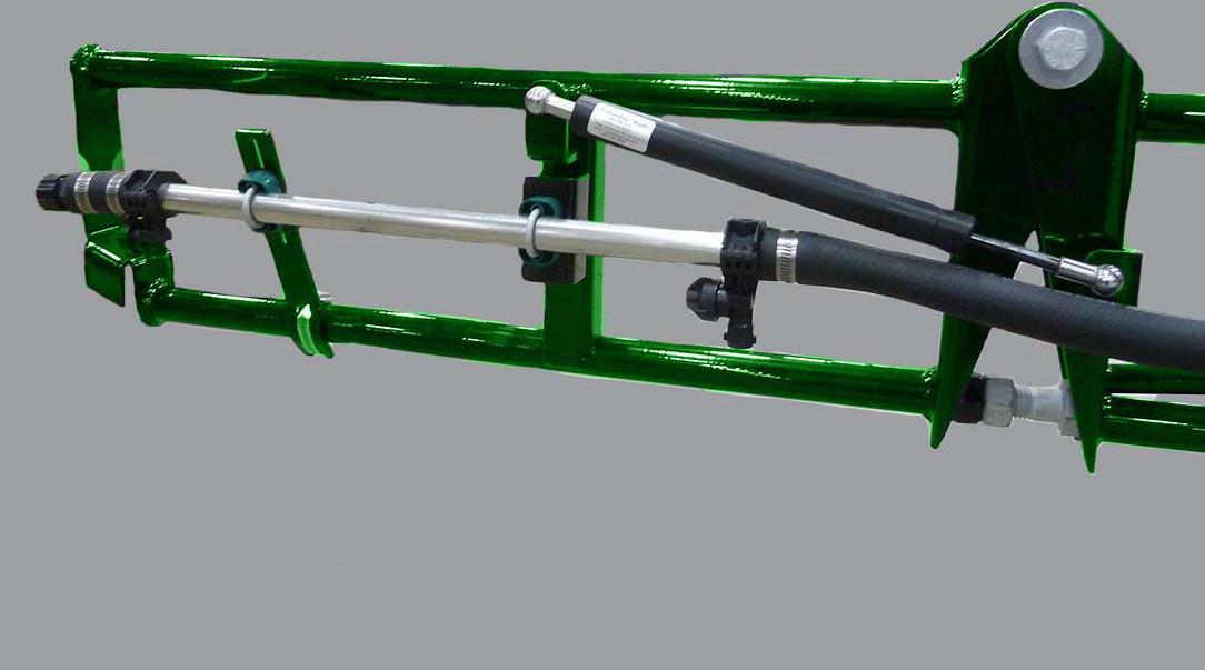
Hydraulic Motor Driven Chemical Pump
Install and tighten the drain plug at the bottom of the pump. Set hydraulic outlet flow to 2.8-4.8 GPM for optional pump output
Performance Chart
Sprayer Adjustment And Calibration
Adjust The Height Of Boom
The height of the sp rayer booms is adjustable between 18 to 60 inches (46 to 152 cm) depending on tractor size and height.
Height is regulated by the tractor lifting or lowering the sprayer. The size of the tractor affects the height of the sprayer. When height adjustment is necessary follow these steps.
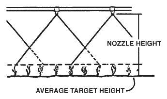
Adjust the height of the boom according to the instructions of the chemical being applied. If not specif ied adjust the booms to be 18 to 20 in (45 to 50 cm) above the target of the spray. Spray pattern from nozzles should overlap a couple inches above the spray target.
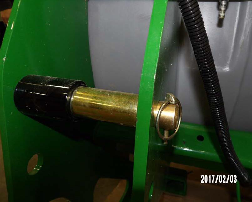
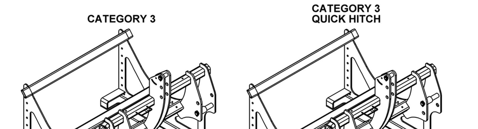
Hitch Adjustment
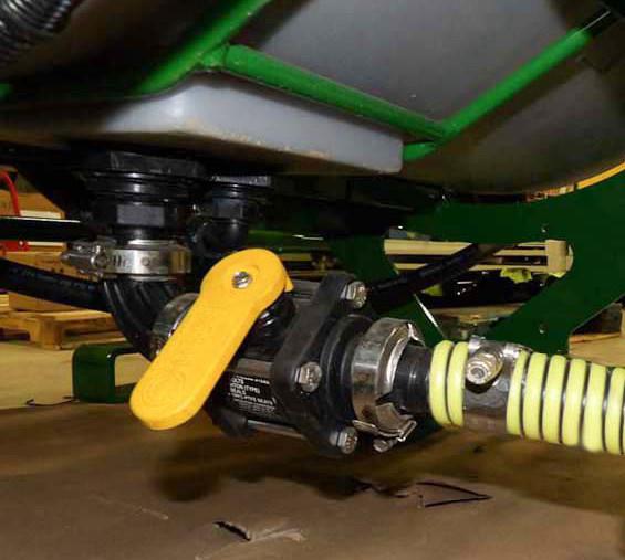
1.Close the tank valve.
2.Disconnect the sprayer from the tractor.
3.Remove the locking pin then remove hitch pins.
Stop tractor engine, plac e all controls in neutral, set parking brake, remove ignition key and wait for all moving parts to stop before servicing.
Calculate the height adjustment needed to determine where to make the adjustment.
NOTE: Height adjustment can be made at the 3 point hitch or at the wings, or both.
4.Move the center pin to the upper, middle or lower position. Reinstall locking pin.
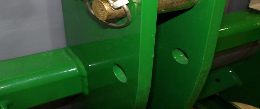
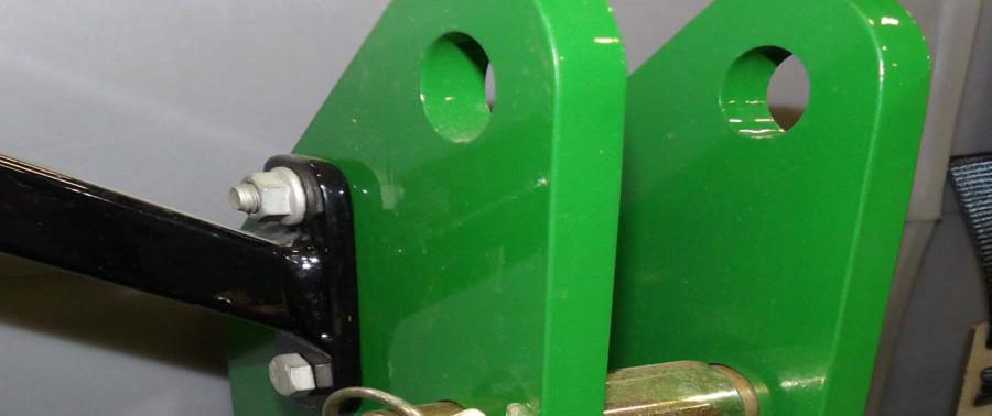
5.Move the side hitc h pins to the upper or lower position. Reinstall locking pin.
NOTE: Both of the side hitch pins must be installed at the same level position.
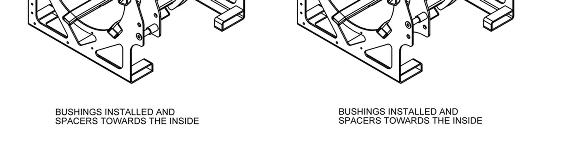
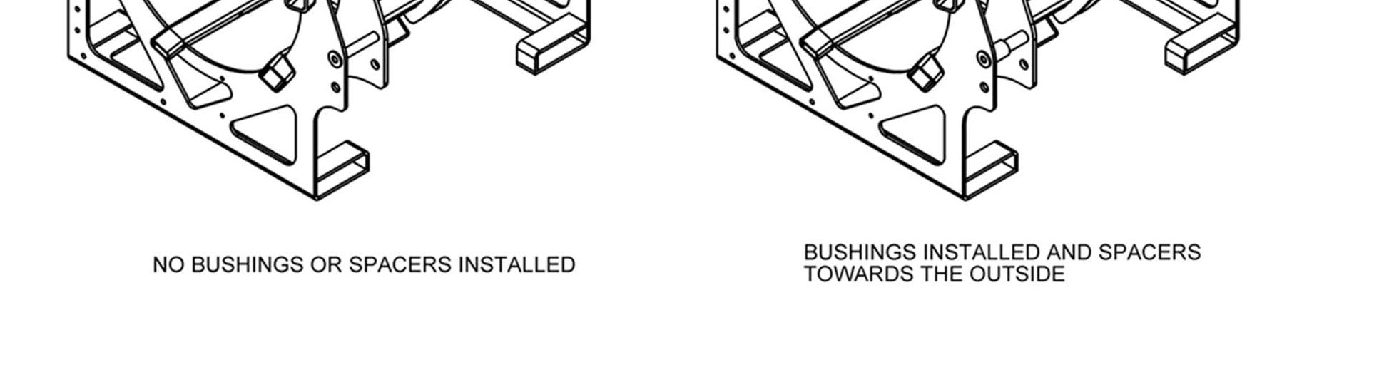
Three Point Hitch Bushings and Spacers
Follow the diagram above for instal ling bushing or spacers as needed.

Boom Height Adjustment (Manual)
Leveling the Booms
For most accurate flow rates and performance, the booms should be level.
1.The sprayer must be on a level surface. Be sure the mainframe is level before adjusti ng the booms.
2.Fold out the wings.
3.Level across the main wing and flip wing.
1.Close the tank valve.
2.Lower sprayer to the ground.
3.Disconnect the spra yer from the tractor.
4.Unfold the main wing section.
5.Place blocks under wings and center boom section to support.
6.Uninstall the 3 bol ts holding the boom to the frame.
7.Repeat on the other side of the frame.
8.Move boom up or down aligning with the holes in the frame.
9.Reinstall and tighten al l bolts to secure the boom.
Adjustment Nuts
To adjust main wing:
•Tighten or loosen the nuts on the eye bolt connecting the main wing to center boom plate.
To adjust the wing tip:
•Tighten or loosen the stop bolt at the inside of the boom.
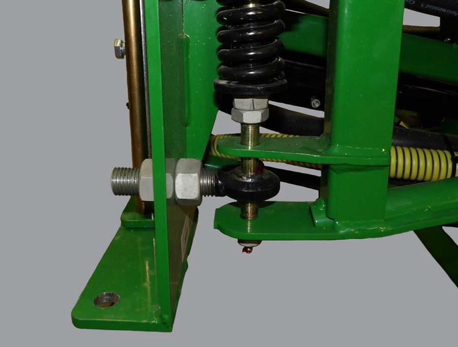
Breakaway Clutch Tension
Bottom of plate
3 5/8 in. 9.2 cm
Bottom of washer
Measure from the botto m of the plate to the bottom of the washer.
•Standard measurement is: 3 5/8 in.(9.2 cm).
To adjust breakaway clutch tension:
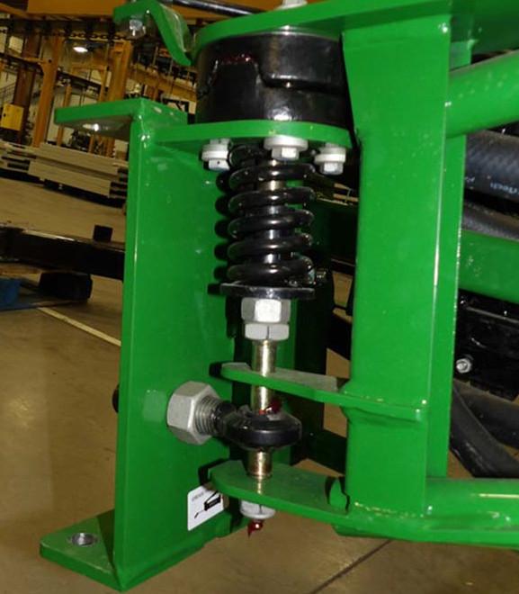
1.Loosen the jam nut.
2.Adjust the nut below the spring.
•Tighten to increase pressure.
•Loosen to decrease pressure.
3.Tighten jam nut to secure.
4.Check boom leveling after adjusting breakaway clutch tension.
Sprayer Calibration
A sprayer can onl y apply the proper amount of chemicals when each component in the system is functioning properly. Chemical action in the field is dependent upon the accurate appl ication of minute amounts of the sp ray compound. A complete calibration of the machine is required at the start of each season or when changing chemicals durin g the spray season.
It is the responsibility of the customer to determine the amount of chemical that they want to apply for their particular application. Many factor s affect how much chemical is applied such as, nozzle flow rate, chemical circuit pressure, pump speed, ground speed to name a few. In this section, instructions are given on how to accurately determi ne flow rates or application rates and how to change them. It is recommended that this procedure is followed carefully so you know exactly how much chemical is being applied.
Work closely with your chemical supplier, nozzle manufacturer, and pest control specialists to equip and operate your machine to obtain the best resu lts. Several nozzle types are available fo r the sprayer. Use the type appropriate fo r your application.
Engine RPM
Although the exact va lue of the engine speed is not particul arly important to sprayer function, it is recommended that it always be set at 2/3 or more throttle position. This will ensure that there will be sufficient oil flow through the hydraulic system and sufficient power to maintain the ground speed.
Select the desired engine RPM and always perform the ca libration and run in the field at the same setting.
If your sprayer is equipped with a PTOdriven pump, run the engine RPM to achieve the 540 PTO RPM.
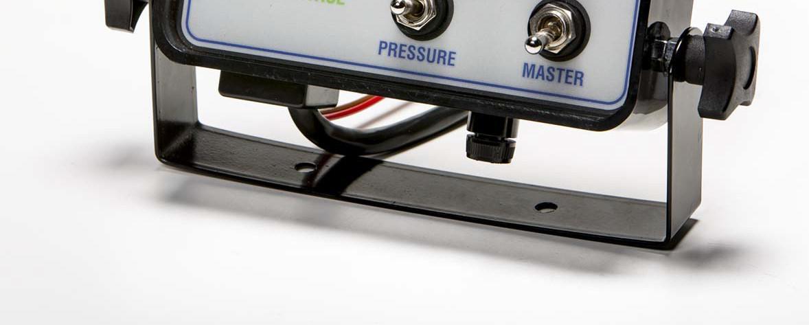
Automatic Controller Calibration (If equipped)
The controller must be set and calibrated for your specific machine. Refer to the Controller manual and follow its Calibration procedure. Use the same controller settings during spra yer component calibrations as used in the field.
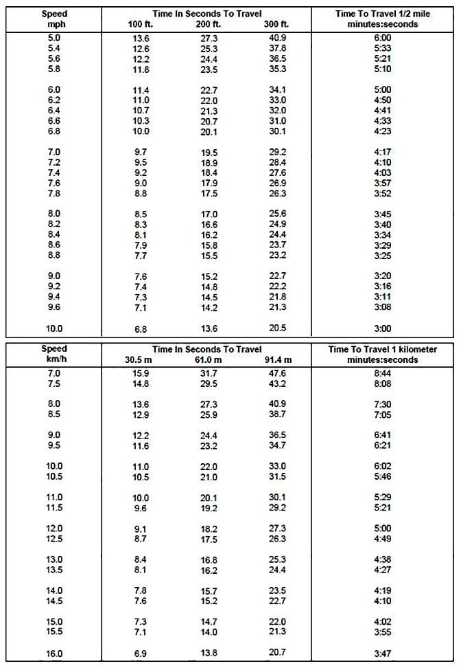
Ground Speed Calculation
For optimum spraying re sults, it is important to maintain a known constant speed to spray the required chemical over a given area. Because of w heel slippage, the operator cannot rely on the tractor speedometer reading to gi ve the value of true ground speed. The unit must be timed over a known distan ce to determine true ground speed.
To calibrate, follow this procedure:
1.Mark off distance of 100, 200 or 300 feet in the field to be sprayed (longer distances provide greater accuracy).
2.Place the tractor in the gear to give a speed between 6 and 8 mph (9.5 and 13 kph) and at the selected engine RPM.
3.With the tank 1/2 full of water, drive the tractor and sprayer through the measured distance.
4.Record the time r equired to travel the measured distance.
IMPORTANT: Always operate at the engine RPM that will be used while spraying the field.
If the machine is equipped with the automatic controller, the ground speed can be changed by up to 20% without requiring adjustments. However, do not decrease the throttle below its 2/3 setting.
If your sprayer is equipped with a PTOdriven pump, run the engine RPM to achieve the 540 PTO RPM.
Nozzle Calibration
Boom Spray Nozzle
The spray nozzles on your sp rayer are TP11002, refer to the calibration chart below. Using tractor speed, nozzle si ze, and desired gallons per acre (GPA), find the pressure (PSI) necessary to achieve your GPA.
NOTE: Lower pressure settings will result in less spray drift.
Standard Calibration Chart
Tip
TP11002 of One NozzleGPA
Boomless Spray Nozzle
The spray nozzles on your sprayer are XT020, refer to the calibration chart below. Using tractor speed, nozzle size, and desired gallons per acre (GPA), find the pressure (PSI) necessary to achieve your GPA.
Boomless Calibration Chart for 48" Height
Tip SizePSIGPM of One NozzleGPA Across 30' Swatch
Travel Speed
Crop and plant type wi ll determine the travel speed for spraying.
Read the product label. Always follow the instructions fo r the product being applied.
Cereal crops - broadcast planting:
A travel speed of 6 to 10 mph (9.7 to 16 km/ hr) is recommende d under most operating conditions. Adju st speed as appropriate for the conditions and according to the product label.
Row Crops:
A travel speed of 4 to 10 mph (6.4 to 16 km hr) is recomme nded in row crops. For crops that have a dens e foliage canopy, a slower speed gives more time for the spray to open the pl ant canopy and allow the chemical to get inside and coat the underside of the leaves. However, operate at a speed that is appropriate for the conditions and according to the product label.
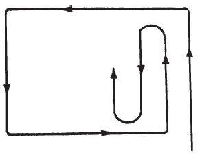
For broadcast spraying: It is recommended that the operator make one pass around the field to start and then spray back and forth to obtain the best results. Usin g a marker system helps to prevent skips or overlap.
For row crop spraying
Start at the edge of the field and go back and forth until the field is completed.
When completing a pass maintain the tractor rpm and ground speed until the nozzles pass over t he plants. This will insure consistent appl ication rates at the end of rows.
If the field has headlands, be sure to allow sufficient space for turning.