5 minute read
ADJUSTMENTS


FRONT & REAR AUGER SLIDES
The front and rear auger slide assemblies are retained by adjustment plates with diagonal slots. To adjust, loosen retaining hardware and drive the plates downward with a hammer until the slide assembly is snug against the tank, then re-tighten the retaining hardware. Grease the slide assembly to ensure a leak free seal.
Discharge Gate
The discharge gate is retained by adjustable angles that secure the gate to the tank through diagonal slots. To adjust, loosen retaining hardware and drive the angles downward with a hammer until the discharge gate is snug against the tank, then re-tighten the retaining hardware. Grease the discharge gate to ensure a leak free seal.
Expeller
Periodically inspect the expeller teeth for wear or damage. Damaged, broken, or missing expeller teeth will cause excessive machine vibration. Consult with your local Frontier dealer for additional ordering information.
AUGER & EXPELLER SPEED OPTIONS
The expeller input drive sprocket can be changed by raising the auger and then removing the indicated sprocket which is retained by a snap ring and set screws.
The auger input drive sprocket change requires removal and disassembly of input shaft.
NOTE: When making sprocket changes, some chain length modifications may be required depending on the condition of the chain and size of the sprocket installed.
SHEAR BOLTS Expeller Shear Device
The discharge expeller sprocket has two ¼” x 1-1/2” grade 8 shear bolts with locknuts. Access is obtained by opening the expeller shield over the front expeller bearing. Additional shear bolts are stored on the expeller front bearing mount.
To replace the expeller shear bolts, proceed as follows:
1.Disengage the PTO.
2.If the object is not lodged in the discharge door opening, close the discharge door to stop the flow of material.
3.Shut-off tractor and remove key.
4.Open the expeller shield over the front expeller bearing.
5.Remove any pieces of the shear bolt that may be still in the shear device.
6.Check to see if the expeller rotates freely. The object may still be present in the expeller.
7.Trip the expeller pan to clear any material or object.
8.Line up the shear bolt holes by manually rotating the expeller.
9.Replace both shear bolts using the 1/4” x 1-1/2” Grade 8 shear bolts stored on the expeller front bearing mount.
10.Close the expeller shield, expeller trip pan, and resume operation.
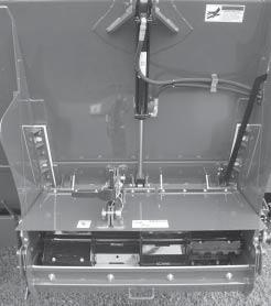
Shield open for viewing
IMPORTANT: When resuming operation, place the tractor throttle at idle before engaging the PTO.
Main Auger Shear Device
The auger jackshaft hub is secured to the auger drive sprocket with two 5/16” x 1-1/2” grade 8 shear bolts and locknuts. Additional shear bolts are stored on the chain tensioner bracket.
If the auger jackshaft bolts shear, proceed as follows:
1.Disengage the PTO.
2.If an object is lodged in the discharge door opening or inside the tank, raise the discharge door, then raise the main auger.
3.Shut-off tractor and remove key.
4.Open the main shield.
5.Remove any pieces of the shear bolt that may be still in the auger jackshaft shear device.
6.Trip the expeller pan to clear any material or objects.
8.Remove any foreign objects from the discharge door opening or inside the tank
9.Line up the shear bolt holes on the auger jackshaft shear device.
9.Replace both shear bolts using the 5/16” x 1-1/2” Grade 8 shear bolts stored on the chain tensioner bracket.
10.Close the main shield and resume operation.
IMPORTANT: When resuming operation, place the tractor throttle at idle before engaging the PTO.
TIRES & WHEELS
Check the tire pressure after every 50 hours of operation. Tires should be inflated to the appropriate pressure listed in the table.
Model Tire Pressure
2320 295/75R22.575 - 80 PSI
2320 385/65R22.585 PSI
2320/2326 16.5 x 16.1 – 10 Ply36 PSI
2326 19L x 16.1 – 10 Ply32 PSI
2326 425/65R22.585 PSI
Wheel lug torque should be checked after every 50 hours of operation and tightened to the appropriate torque.
- Wheel bolts must be tightened at 85-95 ft/lbs. of torque on the 2320/2326.
OPTIONAL FEATURES & ACCESSORIES
NOTE: The optional features & accessories listed in this chapter, are shipped with separate instruction for installation, as applicable.
1000 Rpm Pto Drive
Both models can be ordered from the factory with an optional 1000 RPM drive, as desired.
Auger Speed Options
Several different drive sprockets are available to change auger speeds to various spreading needs. Sprockets are available as service parts.
Expeller Speed Options
Several different drive sprockets are available to change expeller speeds to various spreading needs. Sprockets are available as service parts.
Safety Chains
An appropriate-sized safety chain, to accommodate the potential weight of the loaded Manure Spreader, is available.
ELECTRONIC SCALES & COMPONENTS
Model: Digi-Star GT400
An optional factory installed Digi-Star GT400 scale is available for accurate weight measurement for each load spread. The 5-point weighbar system features 3 modes, Net,Tare and Gross.
Model: Digi-Star NT460
An optional factory installed Digi-Star NT460 scale system is available for accurate weight measurement and displaying actual tons per acre. The Indicator has GPS capability and stores pounds of manure spread on individual fields.
Lubrication
Become familiar with all lubrication points and establish a routine to ensure complete lubrication of the Manure Spreader.
General Information
IMPORTANT: Catch and dispose of fluid per local waste disposal regulations whenever service is performed on hydraulic components, valves, cylinders, hoses, etc.
Pto Assembly
Keep the male and female shafts of the PTO well lubricated and free sliding. Failure to observe this precaution will result in excessive pressure being required to collapse or extend the assembly while subject to operating torque. This excessive force may damage the main shaft bearings. Never lubricate the shield surfaces. The shield surfaces must be kept dry, as dirt accumulation on them will cause the shields to bind and not rotate. Dented or damaged PTO shields, will also result in excessive force being applied against the jackshaft. Damaged shields also cause difficulty when installing the assembly. If at any time the shields do not turn freely, they should be checked to determine the cause, and repaired or cleaned. To avoid damage to the main drive bearings, avoid turning sharp corners while PTO is running. Start and Stop PTO slowly to avoid damage to the drive line.
WHEEL BEARING LUBRICATION, CLEAN & RE-PACK INSTRUCTIONS
Grease wheel bearings as needed depending on amount of travel.
Annually disassemble and clean parts in a solvent. Pack bearings with a high grade grease. Reassemble, and tighten nut until a slight drag is felt when wheel is turned. Back nut off and insert cotter pin into first hole that you see as you back the nut off, bend cotter pin over and re-install cap.
Drive Chains
The drive chains are lubricated by a automatic chain oiler. Any time that the discharge door is raised, a specified amount of oil is sent to the brushes on each of the chains. The oiler is adjustable to set the amount that is being discharged. This will extend the life of the drive chains. Keeping the chains aligned with sprockets will also lengthen the life of the sprockets and drive chains.
Cylinders
Oiler brushes on all chains.
The oiler reservoir is located on the left front side by the scraper and jack storage position.
The discharge gate control cylinder shaft and both front and rear main auger cylinders should also be frequently coated with a rust preventative spray or lubricate since the cylinder shaft may remain extended when not being used for a period of time.