6 minute read
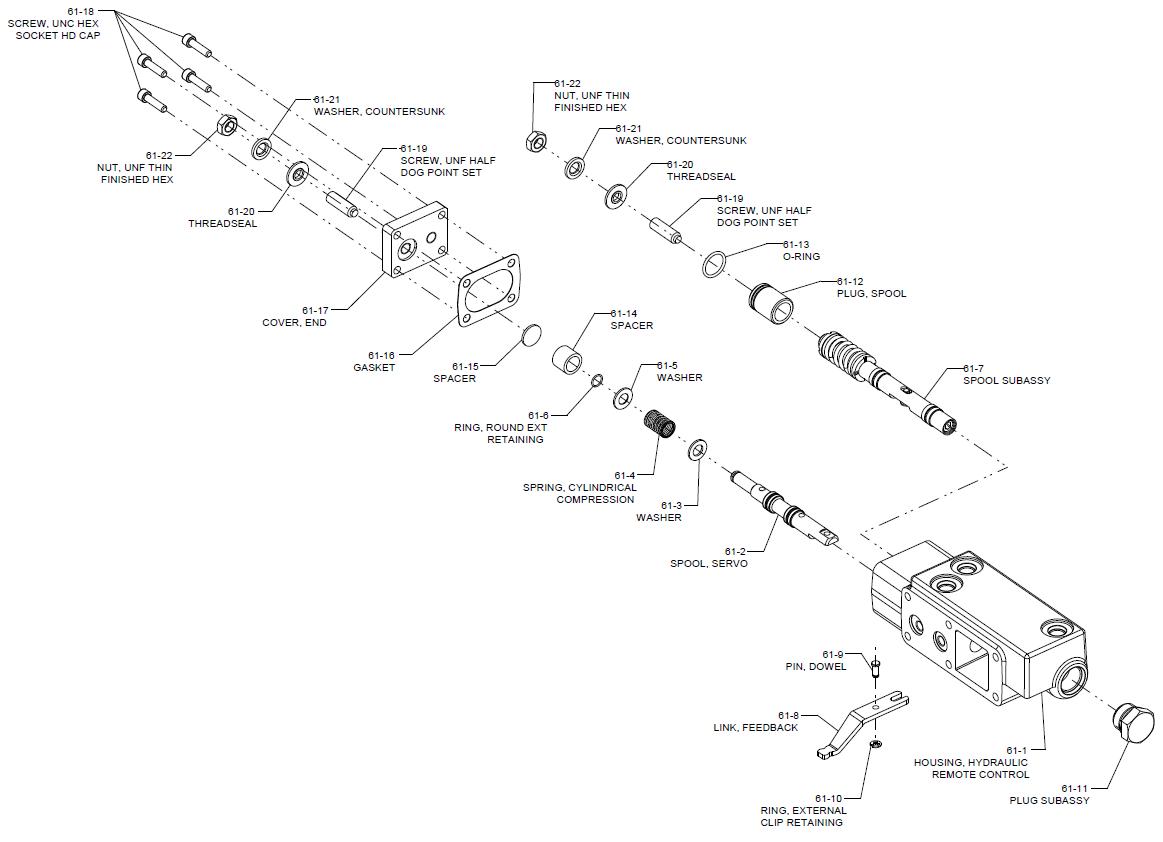
Appendix D – Hydraulic Remote Control Basic Assembly

ITEMQTYDESCRIPTION
61-1 1 HOUSING, HYDRAULIC REMOTE CONTROL
61-2 1 SPOOL, SERVO
61-3 1 WASHER
61-41SPRING, CYLINDRICAL COMPRESSION
61-5 1 WASHER
61-6 1 RING, ROUND EXT RETAINING
61-7 1 SPOOL SUBASSY
61-8 1 LINK, FEEDBACK
61-9 1 PIN, DOWEL
61-10 1 RING, EXTERNAL CLIP RETAINING
61-11 1 PLUG SUBASSY
61-12 1 PLUG, SPOOL
61-13 1 O-RING
61-14 1 SPACER
61-15 1 SPACER
61-16 1 GASKET
61-17 1 COVER, END
61-18 4 SCREW, UNC HEX SOCKET HD CAP
61-19 2 SCREW, UNF HALF DOG POINT SET
61-20 2 THREADSEAL
61-21 2 WASHER, COUNTERSUNK
61-222NUT, UNF THIN FINISHED HEX
Subject: 72400 BACK TO BACK PISTON PUMP REPAIR MANUAL
Disassembly - Hydraulic Remote Control
1) Remove Plug S/A from respective location. Remove Nuts, Washers, Seal Washers & four Set Screws from control end cover. Ensure the orientation of control end cover with corner radius as identification mark.
2) Remove Metal Gasket & Spacer from the control end cover. Remove the dog point set screws from both holes. Note: These set screws are assembled with factory set values and performance of pump may affect if the settings are tampered.
3) Turn the housing & then remove Plug with O- ring from the bigger hole.
4) Remove the retaining ring below the feedback link then remove Pin & Feedback link from control housing
5) Remove the spacers, retaining ring, spring and servo spool from small hole of the housing.
6) Remove servo spool subassembly from the large hole of the control housing.
7) Remove the top Washer then inner and outer spring and another Washer from spool sub assembly. Ensure the orientation of washers; the flat side should always be facing towards spring.
8) Remove Set Screw from opposite side of spool subassembly, the pin to locate feedback link is not required to remove from spool subassembly. Clean all parts and lubricate in prep for reassembly.
Reassembly - Hydraulic Remote Control
1) Adhere safety precautions and use Cloth Gloves and apply Loctite Activator on Screw Threads and on both sides of the Spool. Then follow listed Steps to prepare bigger spool Subassembly: a) Place Spring inside the Spool. b) Place Valve Spool within the Spool by inserting shorter part. c) Insert the set screw in the Spool so that Check Valve Spool will remain centered. Adjust the set screw with Allen wrench 3/16 until the pin on inner spool is centered. d) Insert the washer on set screw with flat side facing towards spring, then place the spring stop on the Screw. e) Insert the spring in the screw, place the washer with lines up and Apply Loctite 271. f) Assemble this set screw the large spool and apply Torque 6-9 lbf – ft. g) Apply oil to the tip of the big spool then enter the spool within the housing by the large hole.
2) Apply oil on the smaller spool, Place the spool in the small hole of the housing. Confirm the orientation of the spool for pin location.
3) Place the Feedback link on the side the orifice & Enter the Pin linking the Feedback link with the spool.
4) Place the retaining ring on the tool and place below the feedback link to secure the feedback link at place.
5) Turn the housing, then insert the Plug, spool with O- ring in the bigger hole.
6) Insert the washers, spring and Spacer in the small hole. Ensure to install the washer with chamfer toward retaining ring. Then install retaining ring.
7) Place the metal gasket on the face of control housing.
8) Insert 4 numbers of screws in servo end covers respective holes and apply Torque of 5 to 6 lbf•ft. Ensure the correct orientation of servo end cover with corner radius
9) Insert Set Screws of spool on end covers with Seal Washers on it.
10) Place Washers & Nuts on Set Screws, then tighten it till it restricts Spool movement.
11) Turn the Housing & Place Plug S/A in the respective location. Torque 3/4 in. plug 28 to 32 N•m [21 to 24 lbf•ft].
Subject: 72400 BACK TO BACK PISTON PUMP REPAIR MANUAL
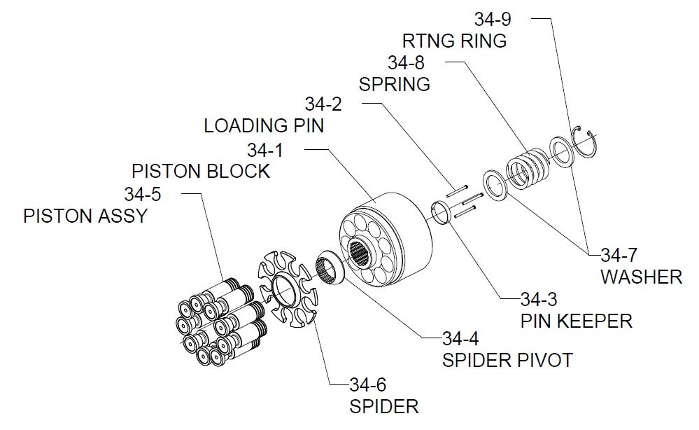
Appendix E - Rotating Kit Assembly
Note: The front pump and rear pump uses identical rotating kit assembly. So this procedure can be repeated for rotating kit assembly on rear pump.
Disassembly – Rotating Kit Assembly
Disassembly of rotating assembly is required for inspection only.
1. Remove the nine piston assemblies, shoe retainer, and shoe retainer pivot from cylinder barrel.
Inspection:
• Examine the O.D. of the pistons for finish condition. They should not show wear or deep scratches. Inspect the shoes for a snug fit on the ball end of the pistons and a flat smooth surface that comes in contact with the Swashplate. Do not lap piston shoes.
• Examine the shoe retainer for wear in the pivot area.
• Examine the pivot to insure smoothness and no signs of wear.
72400 Back To Back Piston Pump Repair Manual
• Inspect the cylinder barrel surface that makes contact with valve plate. This surface should be smooth and free of deep scratches. Do not lap piston block.
• The pistons should move freely in the cylinder barrel bore. If they are sticky in the bore, examine the bore for scoring or contamination.
2. To inspect pins and spring caution should be taken in removing spring. The spring is highly compressed and the retaining ring should not be removed without compressing the spring safely.
The following parts are required to disassemble the cylinder barrel:
2 ea. 3/8 in. I.D. x 1-1/8 in. O.D. flat washers
1 ea. 3/8 in. x 3-1/4 in. N.C. cap screw, and
1 ea. 3/8 in. N.C. nut
To remove spring, place one of the flat washers over the 3/8 in. x 3-1/4 in. cap screw. Put cap screw through the center of the cylinder barrel and apply the second washer. Let washer rest on the three pins and retain with nut. Turning nut and compressing spring inside the barrel. Use a pair of retaining ring pliers and remove the internal retaining ring. Remove nut, bolt, and the two washers from barrel. Remove the washer, spring, second washer, three pins, and pin keeper at the same time.
Reassembly – Rotating Kit Assembly
1. To reassemble the rotating kit assembly, complete the following: Compress the pin keeper and install in the spline of the cylinder barrel. Install the three pins with head end to the inside of the barrel and position in the special grooves of the cylinder barrel spline.
2. Install the washer, spring, and second washer into the cylinder barrel. Use the two 3/8 in. I.D. washers, nut, and 3/8 in. x 3-1/4 in. cap screw to compress the spring and retain with retaining ring. Remove the nut, cap screw, and the two washers.
3. Install the pivot onto the three pins, shoe retainer on the pivot, and piston assemblies thru the shoe retainer and into cylinder barrel, resting on shoe retainer.
Subject: 72400 BACK TO BACK PISTON PUMP REPAIR MANUAL
Start-up Procedure
When initially starting a new or a rebuilt transmission system, it is extremely important that the start-up procedure be followed. It prevents the chance of damaging the unit which might occur if the system was not properly purged of air before start-up.
1. After the transmission components have been properly installed, fill the servo pump housing at least half full with filtered system oil. Connect all hydraulic lines and check to be sure they are tight.
2. Install and adjust all control linkage.
3. Fill the reservoir with approved oil that has been filtered through a 10 micron filter. Refer to Eaton Hydraulics Technical Data sheet number 3-401 titled Hydraulic Fluid Recommendations.
4. Gasoline or L.P. engines: remove the coil wire and turn the engine over for 15 seconds. Diesel engines: shut off the fuel flow to the injectors and turn the engine over for 15 seconds.
5. Replace the coil wire or return the fuel flow to the injectors. Place the transmission unit in the neutral position, start the engine and run it at a low idle. The charge pump should immediately pick up oil and fill the system. If there is no indication of fill in 30 seconds, stop engine and determine the cause.
6. After the system starts to show signs of fill, slowly move pump Swashplate to a slight cam angle. Continue to operate system slowly with no load on motors until system responds fully.
7. Check fluid level in the reservoir and refill if necessary to the proper level with approved filtered oil.
8. Check all line connections for leaks and tighten if necessary.
9. The machine is now ready to be put into operation.
10. Frequent filter changes are recommended for the first two changes after placing the machine back into operation. Change the first filter in 3-5 hours and the second at approximately 50 hours approx. hours. Routinely scheduled filter changes are recommended for maximum life of the hydraulic system.