
4 minute read
Machine description - Instruments/Controls


Function description of instruments and controls in the cab
SymbolFunction
Press to operate the front screen wiper.
Press to operate the rear screen wiper.
3Front and rear window screen washers, switch
Press at the top to spray the windshield.
Press at the bottom to spray the rear windshield.
4Hammer for emergency exit
5Control, temperature (Optional)
6Control, circulation (Optional)
7Control, fan (Optional)
8 AC, switch (Optinal)
To escape from the cab in an emergency, release the hammer and break the REAR window.
In the left position, the heating is OFF.In the right position, maximum heating.
In the left position, the circulation is OFF. In the right position, maximum circulation
In the left position, the fan is OFF. In the right position, maximum fan.
9Cab lighting, switch (Optional) Push in to turn on cab lighting (Optional)
10Windscreen wiper fluid container (Optional) Fill with screenwash as required.
11Handbook compartment Stowage space for safety manual and instruction books.
2016-1-15
4812273251-EN.pdf
2016-1-15
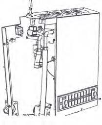
Fuses and relays
The electrical regulating and control system is protected against overload by fuses and relays. The number of fuses and relays is dependent on how much extra equipment the machine in question has.
The fuse boxes and relays are located behind the column cover on the lower part of the instrument column, as illustrated. The cover for the fuses is removed with 2 screws (1). To access the relays, open the entire cover by unscrewing the screws ( 2) according to fig.
The machine is equipped with a 12V electrical system and an AC alternator.
Connect the correct polarities (earth) to the battery. The cable between battery and alternator must not be disconnected when the engine is running.
Location, fuses and relays
The figure shows the position of the different relays in the machine.
3.Fuse box, left side
4.Fuse box, right side
5.VBS relay
6.Relay, hourmeter
7.Relay, front working light
8.Relay, rear working light
Fuse boxes, left side
Machine description - Electrical system
Fuses
The figure shows the position of the fuses. The table below gives fuse amperage and function. All fuses are flat pin fuses.
Fuse boxes, right side
Main fuses
The main fuse (1) is placed by the battery disconnector. The fuse is of the flat pin type. The starter relay (3) are also fitted here.
Main
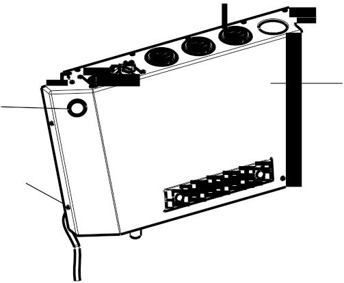
Fig. Heater box in cab.
2016-1-15
Machine description - Electrical system
Fuses and relay in cab heater box (Optional)
To access the fuses (x2) in the heater box, release the plug (1)
The relay in the heater box is accessed by releasing the screws (2) and (3) on the top of the cover, and the screws (3) on the front of the cover, after which the cover (4) can be lifted off the heater box.
Fuses in heater box
To access the fuses (x2) in the heater box, release the plug (1). Unscrew the cover (7) on the fuse box.
5.20 A Fan
6.20 A AC (Optional)
Relay in heater box
4812273251-EN.pdf
Operation - Starting
Operation - Starting
Before starting
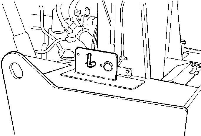
Master switch - Switching on
Remember to carry out daily maintenance. Refer to the maintenance instructions.
The master switch is located in the engine compartment. Turn the key (1) to the on position. The entire roller is now supplied with power.
The engine hood must be unlocked when operating, so that the battery can be quickly disconnected if necessary.
Driver seat (Std.) - Adjustment
Adjust the operator’s seat so that the position is comfortable and so that the controls are within easy reach.
The seat can be adjusted lengthways (1).
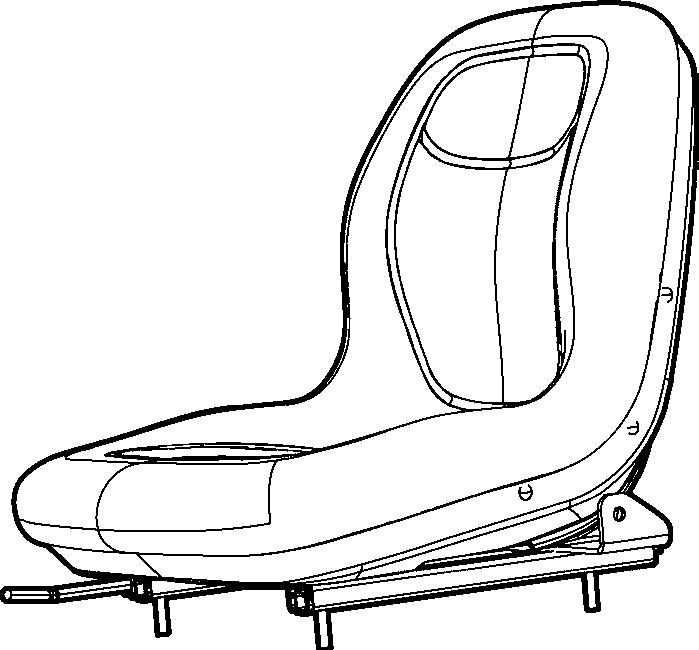
Driver seat (Option)- Adjustment
Adjust the operator’s seat so that the position is comfortable and so that the controls are within easy reach.
The seat can be adjusted as follows.
- Length adjustment (1)
- Weight adjustment (2)
- Back support angle (3)
Always make sure that the seat is secure before beginning operation.
Do not forget to use the seat belt (4).
Instruments and lamps - Checking
Turn the starter switch (2) to position I.
Check that the fuel gauge (17) gives a reading.
Check that the warning lamps for charging (7), oil pressure (9) and the parking brake (8) come on.
Operation - Starting
Parking brake - Check
Make sure that the emergency/parking brake knob (5) really is in the depressed position and that the warning lamp for the brake system (8) is on. The roller can start to roll when the engine is started on sloping ground, if the emergency/parking brake is not applied. Operator
Position
If a ROPS (2) (Roll Over Protective Structure) or a cab is fitted to the roller, always wear the seat belt (1) provided and wear a protective helmet.
Replace the seat belt (1) if it shows signs of wear or has been subjected to high levels of force.
Check that rubber elements (3) on the platform are intact. Worn elements will impair comfort.
Ensure that the anti-slip (4) on the platform is in good condition. Replace where anti-slip friction is poor.
If the machine is fitted with a cab, make sure that the door is closed when in motion.
Operation - Starting
View
Before starting, make sure that the view forwards and backwards is unobstructed.
All cab windows should be clean and the rear view mirrors should be correctly adjusted.
Interlock (Optional)
The roller can be equipped with Interlock.
The engine switches off 7 seconds after the operator rises from the seat.
The engine stops whether the forward/reverse lever is in the neutral or the drive position.
The engine does not stop if the parking brake is activated.
Operation - Starting
Starting
Starting the engine
Set the forward/reverse lever (20) in neutral. The engine can only be started when the lever is in neutral.
Set the amplitude selector (13) for Low/High vibration to position O.
Set the engine speed control (16) to the idling mode.
Turn the starter switch (2) to the right to position I. Then activate the starter motor by turning one position further.
Do not run the starter motor for more than 30 sec. 2 minuntes to start the engine. If the engine does not start immediately, wait for
Let the engine idle for 2-5 minutes to warm, longer if the ambient temperature is below +10°C (50°F).
While the engine is warming up, check that the warning lamps for oil pressure (9) and charging (7) are turned off. The warning lamp (8) for the reserve/parking brake should still be lit.
Ensue that there is good ventilation (air extraction) if the engine is run indoors. Risk of carbon monoxide poisoning.
When starting up and driving a cold machine, which implies cold hydraulic fluid, the braking distance will be longer than normal until the machine reaches working temperature.
4812273251-EN.pdf 2016-1-15