8 minute read
Instructions manual


lCA510-CN2EN.pdf
4812273251.pdf
Driving & Maintenance
CA510
EngineEngine
Cummins 6BTAA5.9-C170
Serial number 10000128x0C004141 - the of of on and weathered
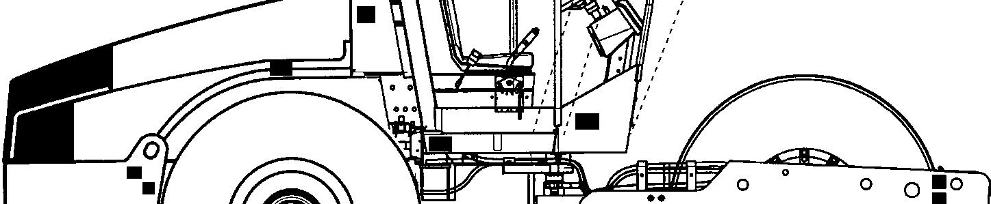
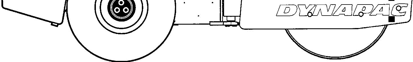
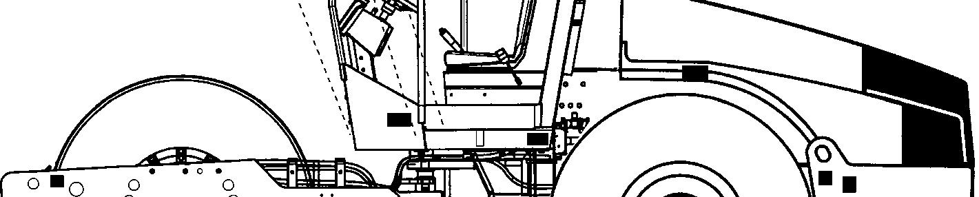
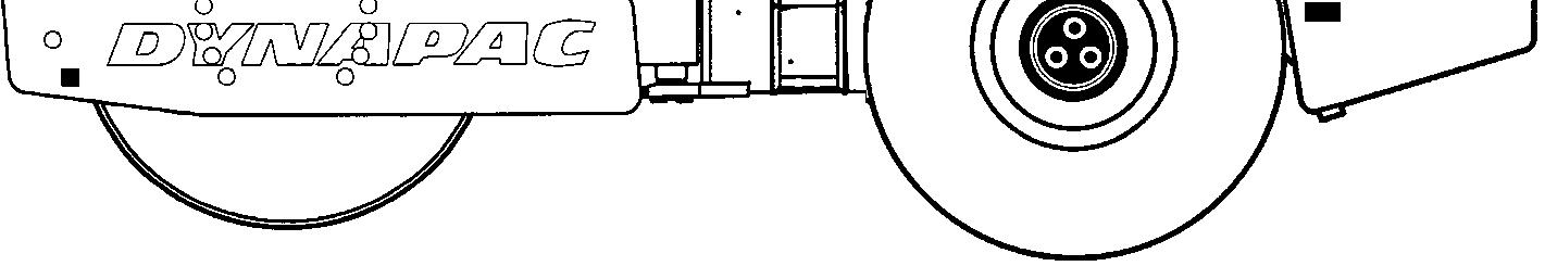
The Dynapac CA510 is a roller in the 18-ton class. CA510 is available in D (smooth drum) and PD (padfoot drum) versions. CA510D is intended for the compaction of rockfill. The main area of application for the CA510PD is on cohesive material andweathered stone material.
All types of base courses and subbase courses can be compacted deeper and the interchangeable drums, D to PD, and vice versa, facilitate even greater variety in the range of application.
The cab and safety-related accessories are described in this manual.

2016-1-15
Introduction
Warning symbols
WARNING ! Marks a danger or a hazardous procedure that can result in life threatening or serious injury if the warning is ignored.
CAUTION ! Marks a danger or hazardous procedure that can result in damage to the machine or property if the warning is ignored.
Safety information
The safety manual supplied with the machine must be read by all roller operators. Always follow the safety instructions. Do not remove the manual from the machine.
We recommend that the operator reads the safety instructions in this manual carefully. Always follow the safety instructions. Ensure that this manual is always easily accessible.
Read the entire manual before starting the machine and before carrying out any maintenance.
Ensure good ventilation (extraction of air by fan) where the engine is run indoors.
General
This manual contains instructions for machine operation and maintenance.
The machine must be correctly maintained for maximal performance.
The machine should be kept clean so that any leakages, loose bolts and loose connections are discovered at as early a point in time as possible.
Inspect the machine every day, before starting. Inspect the entire machine so that any leakages or other faults are detected.
Check the ground under the machine. Leakages are more easily detected on the ground than on the
4812273251-EN.pdf machine itself.
The attachment or installation of additional devices, which are used to intervene in the function of the machine or with which its function are supplemented, is only permitted with the written approval of the manufacturer.
If necessary, approval should be sought from local authorities.
Consent from the authorities is however no substitute for approval from the manufacturer.
THINK ENVIRONMENT ! Do not release oil, fuel and other environmentally hazardous substances into the environment. Always send used filters, drain oil and fuel remnants to environmentally correct disposal.
This manual contains instructions for periodic maintenance normally carried out by the operator.
Additional instructions for the engine can be found in the manufactuer's engine manual.
Safety - General instructions
Safety - General instructions
(Also read the safety manual)
1.The operator must be familiar with the contents of the OPERATION section before starting the roller.
2.Ensure that all instructions in the MAINTENANCE section are followed.
3.Only trained and/or experienced operators are to operate the roller. Passengers are not permitted on the roller. Remain seated at all times when operating the roller.
4.Never use the roller if it is in need of adjustment or repair.
5.Only mount and dismount the roller when it is stationary. Use the intended grips and rails. Always use the three-point grip (both feet and one hand, or one foot and both hands) when mounting or dismounting the machine. Never jump down from the machine. chine.
6.The ROPS (Roll Over Protective Structure) should always be used when the machine is operated on unsafe ground.
7.Drive slowly in sharp bends.
8.Avoid driving across slopes. Drive straight up or straight down the slope.
9.When driving close to edges, ditches or holes, make sure that at least 2/3 of the drum width is on previously compacted material (solid surface). at the
10.Make sure that there are no obstacles in the direction of travel, on the ground, in front of or behind the roller, or overhead. or
11.Drive particularly carefully on uneven ground.
12.Use the safety equipment provided. The seat belt must be worn on machines fitted with ROPS.
13.Keep the roller clean. Clean any dirt or grease that accumulates on the operator platform immediately. Keep all signs and decals clean and legible.
14.Safety measures before refueling:
- Shut off the engine
- Do not smoke
- No naked flame in the vicinity of the machine
- Ground the filling device nozzle to the tank to avoid sparks refueling: smoke avoid
15.Before repairs or service:
- Chock the drums/wheels and under the strike-off blade.
- Lock the articulation if necessary
4812273251-EN.pdf 2016-1-15
Safety - General instructions
16.Hearing protection is recommended if the noise level exceeds 85 dB(A). The noise level can vary depending on the equipment on the machine and the surface the machine is being used on.
17.Do not make any changes or modifications to the roller that could affect safety. Changes are only to be made after written approval has been given by Dynapac.
18.Avoid using the roller before the hydraulic fluid has reached its normal working temperature. Braking distances can be longer than normal when the fluid is cold. See instructions in the STOP section. be own
19.For your own protection always wear:
-
- helmet
- working boots with steel toecaps
- ear protectors
- reflecting clothing/high visibility jacket
- working gloves
- working toecaps- working
2016-1-15
Safety - when operating
Driving near edges
When driving near an edge, minimum 2/3 of the drum width must be on solid ground.
Keep in mind that the machine's center of gravity moves outwards when steering. For example, the center of gravity moves to the right when you steer to the left.
Slopes
This angle has been measured on a hard, flat surface with the machine stationary.
The steering angle was zero, the vibration was switched OFF and all tanks were full.
Always take into consideration that loose ground, steering the machine, vibration on, machine speed across the ground and raising the center of gravity can all cause the machine to topple at smaller slope angles than those specified here.
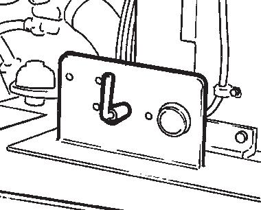
To exit the cab in an emergency, release the hammer on the rear right post and break the rear window.
It is recommended that ROPS (Roll Over Protective Structure) or a ROPS-approved cab is always used when driving on slopes or unsafe ground. Always wear a safety belt.
Where possible, avoid driving across slopes. Drive instead straight up and down sloping ground.
4812273251-EN.pdf
2016-1-15
Safety (Optional)
Air conditioning
The system described in this manual is type ACC (Automatic Climate Control)
The system contains pressurized refrigerant. It is forbidden to release refrigerants into the atmosphere.
The cooling system is pressurized. Incorrect handling can result in serious personal injury. Do not disconnect or undo the hose couplings.
The system must be refilled with an approved refrigerant by authorized personnel when necessary.
4812273251-EN.pdf
Special instructions
Special instructions
Standard lubricants and other recommended oils and fluids
Before leaving the factory, the systems and components are filled with the oils and fluids specified in the lubricant specification. These are suitable for ambient temperatures in the range -15°C to +40°C (5°F - 104°F).
Higher ambient temperatures, above +40°C (104°F)
For operation of the machine at higher ambient temperatures, however maximum +50°C (122°F), the following recommendations apply:
The diesel engine can be run at this temperature using normal oil. However, the following fluids must be used for other components:
Hydraulic system - mineral oil Shell Tellus T100 or similar.
Temperatures
The temperature limits apply to standard versions of rollers.
Rollers equipped with additional equipment, such as noise suppression, may need to be more carefully monitored in the higher temperature ranges.
High pressure cleaning
Do not spray water directly onto electrical components or the instrument panels.
Place a plastic bag over the fuel filler cap and secure with a rubber band. This is to avoid high pressure water entering the vent hole in the filler cap. This could cause malfunctions, such as the blocking of filters.
Never aim the water jet directly at the fuel tank cap. This is particularly important when using a high-pressure cleaner.
Fire fighting
If the machine catches fire, use an ABE-class powder fire extinguisher.
A BE-class carbon dioxide fire extinguisher can also be used.
Special instructions
Roll Over Protective Structure (ROPS), ROPS approved cab
If the machine is fitted with a Roll Over Protective Structure (ROPS, or ROPS approved cab) never carry out any welding or drilling in the structure or cab.
Never attempt to repair a damaged ROPS structure or cab. These must be replaced with new ROPS structure or cabs.
Battery handling
When removing batteries, always disconnect the negative cable first.
When fitting batteries, always connect the positive cable first.
Dispose of old batteries in an environmentally friendly way. Batteries contain toxic lead.
Do not use a quick-charger for charging the battery. This may shorten battery life.
4812273251-EN.pdf
2016-1-15
2016-1-15
Jump starting
Do not connect the negative cable to the negative terminal on the dead battery. A spark can ignite the oxy-hydrogen gas formed around the battery.
Check that the battery used for jump starting has the same voltage as the dead battery.
Turn the ignition and all power consuming equipment off. Switch off the engine on the machine which is providing jump start power.
First connect the jump start battery's positive terminal (1) to the flat battery's positive terminal (2).Then connect the jump start battery's negative terminal (3) to, for example, a bolt (4) or the lifting eye on the machine with the flat battery.
Start the engine on the power providing machine. Let it run for a while. Now try to start the other machine. Disconnect the cables in the reverse order.
4812273251-EN.pdf
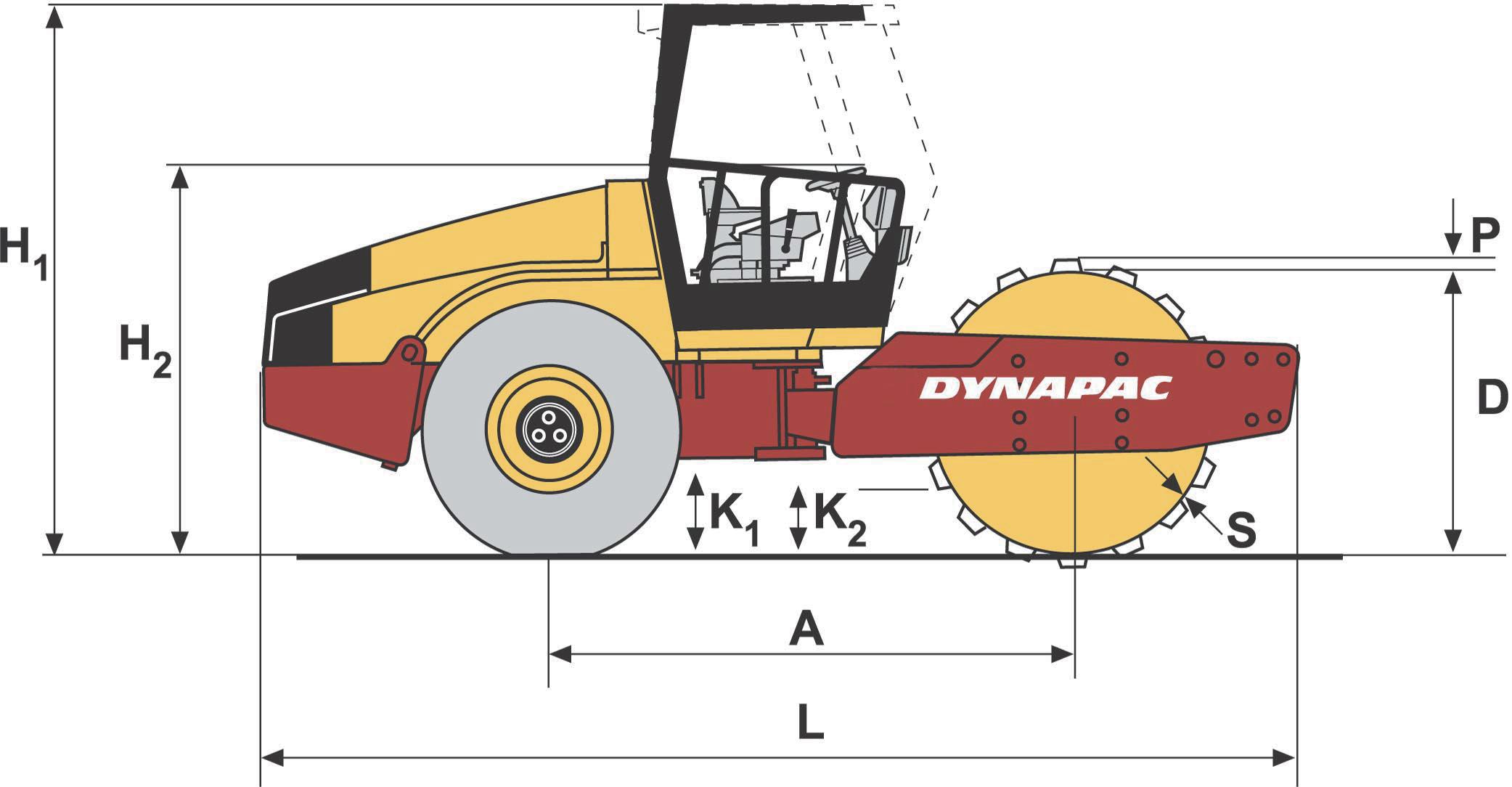
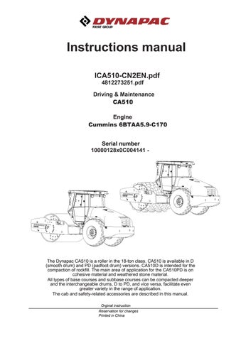
Technical specifications - Dimensions
Technical specifications - Weights and volumes
Technical specifications - Weights and volumes Fluid volumes
2016-1-15
4812273251-EN.pdf
Compaction data
Note: The frequency is measured at high revs. The amplitude is measured as the real value and not the nominal.
Technical specifications - General
Technical specifications - General
Fuses See the Electrical system section - fuses
The tires are filled with fluid, (extra weight up to 500 kg/tire) (1102 lbs/tire). When servicing, bear this extra weight in mind.
Technical specifications - General
Tightening torque
Tightening torque in Nm (lbf.ft) for oiled or dry bolts tightened with a torque wrench.
Metric coarse screw thread, bright galvanized (fzb):
STRENGTH CLASS:
Metric coarse thread, zinc-treated (Dacromet/GEOMET):
4812273251-EN.pdf
2016-1-15
2016-1-15
ROPS-bolts which are to be torque tightened must be dry.
ROPS - bolts
Bolt dimensions :M24 (PN 904562)
Strength class : 10.9
Tightening torque :800 Nm (Dacromet treated)
4812273251-EN.pdf
2016-1-15
Machine plate - Identification
Machine plate - Identification
Product identification number on the frame
The machine PIN (product identification number) (1) is punched on the right edge of the front frame.
Machine plate
The machine type plate (1) is attached to the front left side of the frame, beside the steering joint.
The plate specifies the manufacturers name and address, the type of machine, the PIN product identification number (serial number), operating weight, engine power and year of manufacture. (If the machine is supplied to outside the EU, there are no CE markings and in some cases no year of manufacture.)
Please state the machine's PIN when ordering spares.
4812273251-EN.pdf
10000123V0A123456
ABCDEF
Machine plate - Identification
Explanation of 17PIN serial number
A= Manufacturer
B= Family/Model
C= Check letter
D= No coding
E= Production unit
F= Serial number
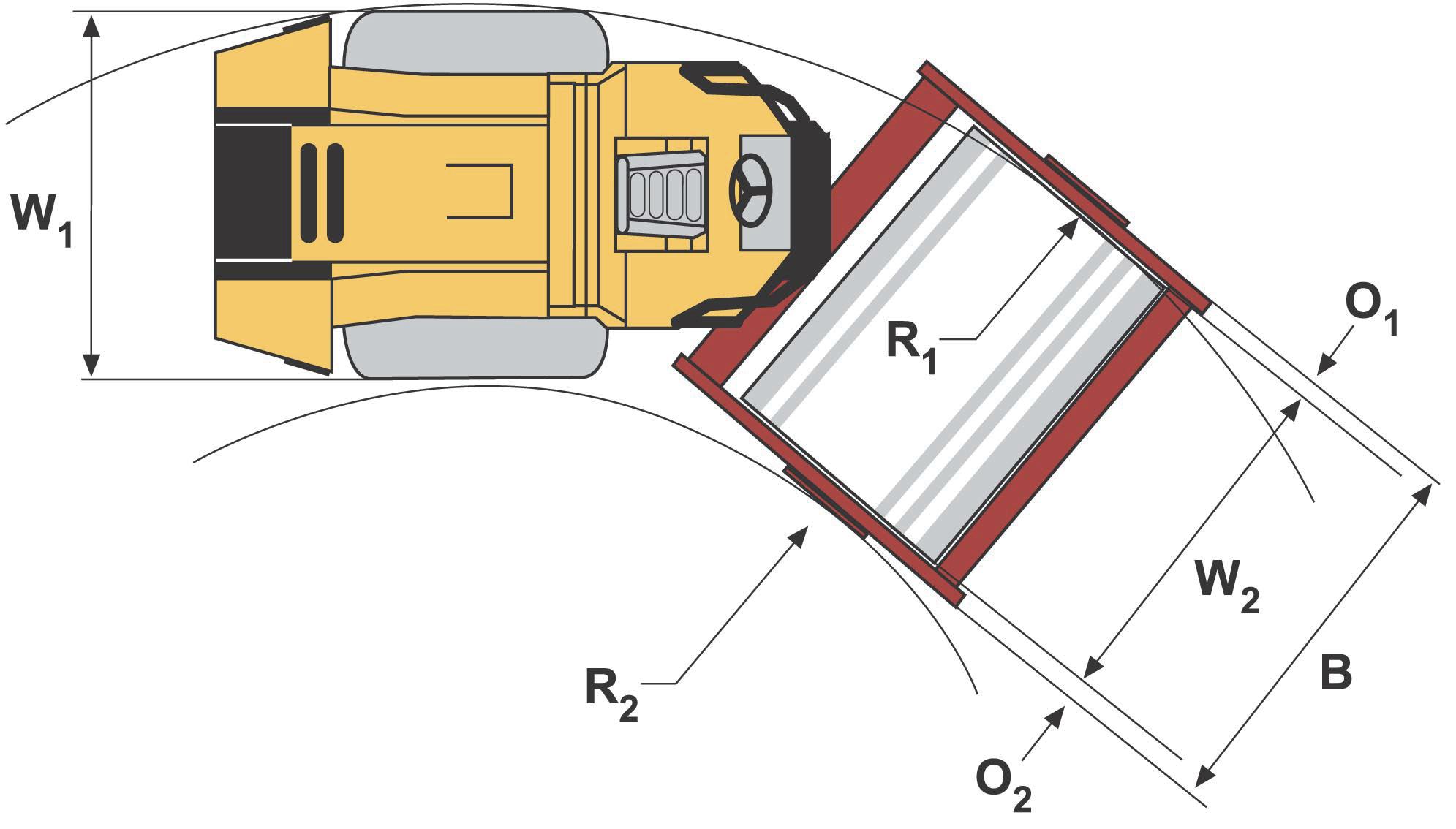
Engine plates
The engine plate (1) is affixed to the right side of the engine.
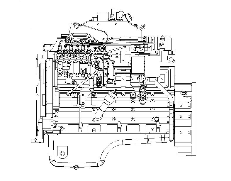
The plate specifies the type of engine, its serial number and the engine specification.
Please specify the engine serial number when ordering spares. Refer also to the engine manual.
4812273251-EN.pdf
2016-1-15
Machine description- Decals


Machine description- Decals
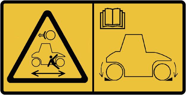
Safety decals
4700903422
Warning - Crush zone, articulation/drum.
Maintain a safe distance from the crush zone. (Two crush zones on machines fitted with pivotal steering)
4700903423
Warning - Rotating engine components. Keep your hands at a safe distance from the danger zone.
4700903424
Warning - Hot surfaces in the engine compartment. Keep your hands at a safe distance from the danger zone.
4700903459
Warning - Instruction manual
The operator must read the safety, operation and maintenance instructions before operating the machine.
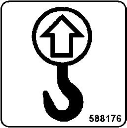
4700908229
Warning - Locking
The articulation must be locked when lifting. Read the instruction manual.
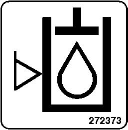
4700904165
Warning - Toxic gas (option, ACC)
Read the instruction manual.
4812273251-EN.pdf
2016-1-15
2016-1-15
4700903590
-Emergency exit
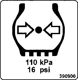
4700903985
Warning - Ballasted tire.
Read the instruction manual.
4700904895
Warning - Brake disengagement
Study the towing chapter before disengaging the brakes.
Danger of being crushed.
4812273251-EN.pdf
Machine description- Decals
Coolant
Info decals
Diesel fuel Lifting point fuel
Hoisting plate
Handbook compartmentMaster switch
Hydraulic fluid
Biological hydraulic fluidSecuring point
Hydraulic fluid level
Tire pressure
4812273251-EN.pdf
2016-1-15
NoDesignation
1Horn, switch
2Starter switch