
36 minute read
Machine description - Instruments/Controls


Function descriptions
NoDesignation SymbolFunction
1Horn, switch
2Starter switch
Press to sound the horn.
The electric circuit is broken.
All instruments and electric controls are supplied with power.
Starter motor activation.
3Hazard beacon, switch (Optional) Turn to the right to switch on the hazard beacon.
4Working lights (Optional)
5Emergency stop
7Warning lamp, battery charging
8Brake warning lamp
9Warning lamp, engine oil pressure/temperature
10Warning lamp, hydraulic filter
11Warning air filter
12Temperature gauge, hydraulic fluid
13Amplitude / Frequency selector, switch
Turn to the right to switch on the working lights.
Push in to activate the emergency stop.
If the lamp comes on while the engine is running, the alternator is not charging. Stop the engine and locate the fault.
The lamp come on when the parking or emergency brake knob is depressed and the brakes are applied.
This lamp lights if the engine is too hot or the oil pressure is too low. Stop the engine immediately and locate the fault. Refer also to the engine manual.
If the lamp comes on while the diesel engine is running at full speed, the hydraulic fluid filter must be changed. Change when the oil is at normal operating temperature.
If the lamp comes on while the engine is running at full speed, the air filter must be cleaned or replaced.
Indicates the temperature of the hydraulic fluid. Normal temperature range 65°-80°C (149°-176°F). Stop the diesel engine if the lamp comes on. Locate the fault.
The left position gives low amplitude / high frequency.
In the central position, amplitude / frequency is switched off.
The right position gives high amplitude / low frequency.
14Speed selector, drum
Transport speed (High)
Working speed (Low)
4812313017-EN.pdf
2018-8-24
NoDesignation
15Speed selector, rear axle
SymbolFunction
Transport speed (High)
Working speed (Low)
16Engins speed control, engine
17Water temperature gauge
18Fuse box
19Vibration On/Off, switch
20Forward/Reverse lever
In the right position, the engine idles. In the left position, the engine runs at maximum speed.
Show engine coolant temperature.
Unscrew the cover to access the fuses.
Push in and release the switch to engage vibration. Press the switch again to disengage vibration. The above applies only when the amplitude selector (13) is in position High or Low.
The lever must be in neutral to start the engine. The engine cannot be started if the forward/reverse lever is in any other position.
The forward/reverse lever controls both the roller's driving direction and speed. When the lever is moved forward, the roller moves forward.
The roller's speed is proportional to the distance the lever is from the neutral position. The further the lever is from the neutral position, the higher the speed.
23Control panel Warning lamps
24Master switch
25Hourmeter
26Parking brake
27Fuel gauge
In the shut off position, the key can be removed. Turn the key a quarter of a turn clockwise to supply the roller with power.
Registers the number of hours that the engine is operated.
Parking brake is applied if it’s rotated to the right position When switch is rotated to the left, parking brake release.
Shows level in the fuel tank.
28 Engine warning lamp (yellow); Engine stop (red).
Warning lamp
29 Engine speed switch Low speed for idle. HI speed for propulsion and working mode.
2018-8-24
4812313017-EN.pdf

NoDesignation
1Control, fan
2Ourside air circling
3 AC, switch
4Control, temperature
Machine description - Instruments/Controls
Function description of instruments and controls in the cab
SymbolFunction
In the left position, the fan is OFF. In the right position, maximum fan.
5Hammer for emergency exit
In the left position, the heating is OFF.In the right position, maximum heating.
6Cab lighting, switch (Optional)
Windscreen wiper fluid container (Optional)
Handbook compartment
9Front wiper, switch
Front window screen washers, switch
To escape from the cab in an emergency, release the hammer and break the REAR window.
Push in to turn on cab lighting
Fill with screenwash as required.
Stowage space for safety manual and instruction books.
Press to operate the front screen wiper.
Press at the top to spray the windshield.
2018-8-24
4812313017-EN.pdf
2018-8-24
Machine description - Electrical system
Fuses and relays
The electrical regulating and control system is protected against overload by fuses and relays. The number of fuses and relays is dependent on how much extra equipment the machine in question has.
The fuse boxes and relays are located behind the column cover on the lower part of the instrument column, as illustrated. The cover for the fuses is removed with 2 screws (1). To access the relays, open the entire cover by unscrewing the screws ( 2) according to fig.
The machine is equipped with a 12V electrical system and an AC alternator.
Connect the correct polarities (earth) to the battery. The cable between battery and alternator must not be disconnected when the engine is running.
Location, fuses and relays
The figure shows the position of the different relays in the machine.
Machine description - Electrical system
Fuses
The figure shows the position of the fuses. The table below gives fuse amperage and function. All fuses are flat pin fuses.
Main fuses
The main fuse (1) is placed by the battery disconnector (4). The fuse is of the flat pin type. The starter relay (3) are also fitted here.
4812313017-EN.pdf
2018-8-24
Machine description - Electrical system
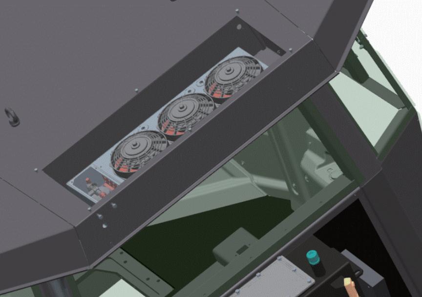
Fuses in cab heater box
To access the fuses box (1) at the top of the cab. 4812313017-EN.pdf
2018-8-24
Operation - Starting
Operation - Starting
Before starting
Master switch - Switching on
Remember to carry out daily maintenance. Refer to the maintenance instructions.
The master switch is located in the engine compartment. Turn the key (1) to the on position. The entire roller is now supplied with power.
The engine hood must be unlocked when operating, so that the battery can be quickly disconnected if necessary.
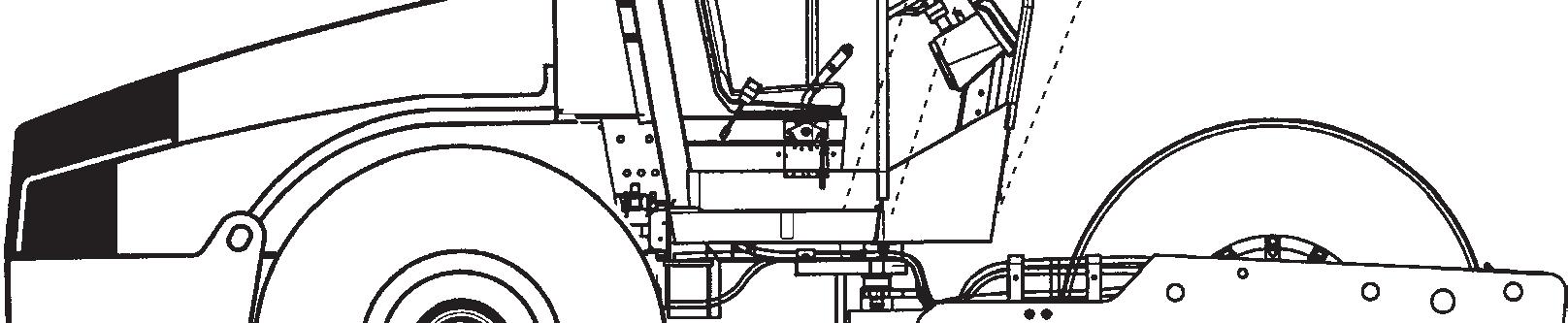
Driver seat (Std.) - Adjustment
Adjust the operator’s seat so that the position is comfortable and so that the controls are within easy reach.
The seat can be adjusted lengthways (1).
4812313017-EN.pdf
Driver seat - Adjustment
Adjust the operator’s seat so that the position is comfortable and so that the controls are within easy reach.
The seat can be adjusted as follows.
- Length adjustment (1)
- Weight adjustment (2)
- Backrest swing (3)
- Seat swing (5)
Always make sure that the seat is secure before beginning operation.
Do not forget to use the seat belt (4).
Instruments and lamps - Checking
Turn the starter switch (2) to position ON.
Check that the fuel gauge (27) gives a reading.
Check that the warning lamps for charging (7), oil pressure (9) and the parking brake (8) come on.
4812313017-EN.pdf
2018-8-24
Parking brake - Check
Make sure that the Parking brake (26) is at rotated to the right position. Warning lamp for the brake brake system (8) is on. The roller can start to roll when the engine is started on the sloping ground, if the parking brake is not applied.
Operator position
If a ROPS (2) (Roll Over Protective Structure) or a cab is fitted to the roller, always wear the seat belt (1) provided and wear a protective helmet.
Replace the seat belt (1) if it shows signs of wear or has been subjected to high levels of force.
Check that rubber elements (3) on the platform are intact. Worn elements will impair comfort.
Ensure that the anti-slip (4) on the platform is in good condition. Replace where anti-slip friction is poor.
If the machine is fitted with a cab, make sure that the door is closed when in motion.
Operation - Starting
View
Before starting, make sure that the view forwards and backwards is unobstructed.
All cab windows should be clean and the rear view mirrors should be correctly adjusted.
Interlock (Optional)
The roller can be equipped with Interlock.
The engine switches off 7 seconds after the operator rises from the seat.
The engine can’t be started when the forward/reverse lever is not in the neutral or it is at the driving position.
The engine does not stop if the parking brake is activated.
Set the forward/reverse lever (20) in neutral. The engine can only be started when the lever is in neutral.
Set the amplitude selector (13) for Low/High vibration to position O.
Set Engine RPM control (29) to low (idle mode) to start.
Turn the starter switch (2) to the right to position ON. Then turn the switch to “Start” to start engine.
Do not run the starter motor for more than 30 sec. 2 minuntes to start the engine. If the engine does not start immediately, wait for
Let the engine idle for 2-5 minutes to warm, longer if the ambient temperature is below +10°C (50°F).
While the engine is warming up, check that the warning lamps for oil pressure (9) and charging (7) are turned off. The warning lamp (8) for the reserve/parking brake should still be lit.
Ensue that there is good ventilation (air extraction) if the engine is run indoors. Risk of carbon monoxide poisoning.
When starting up and driving a cold machine, which implies cold hydraulic fluid, the braking distance will be longer than normal until the machine reaches working temperature.
2018-8-24
Operation - Driving
Operating the roller
Under no circumstances is the machine to be operated from the ground. The operator must be seated inside the machine during all operation.
Turn the engine RPM control (29) and lock it in its limit position; the engine speed should now be approximately 2300 rpm. The speed when idling should be approximately 900 rpm.
Engine run in idle speed must not exceed 10 minutes.
Check that the steering is working correctly by turning the steering wheel once to the right and once to the left while the roller is stationary. Make sure that the work area in front and behind the roller is clear.
Turn the parking brake (26) to the left , the indicator lights off, be prepared that roller may begin to roll.
Set the High/Low speed selectors (14) and (15) to the desired mode, see decal on the instrument panel. Max. speed/hour 4h/mkh/mk 4
Low drum/Low rear axle
The High/High mode may only be used for transport runs on an even surface.
When starting and driving a machine that is cold, remember that the hydraulic fluid is also cold and that braking distances can be longer than normal until the machine reaches the working temperature.
Carefully move the forward/reverse lever (20) forwards or backwards, depending on which direction of travel is required. Speed increases as the lever is moved away from the neutral position.
The speed should always be controlled using the forward/reverse lever and never by changing the engine speed.
4812313017-EN.pdf
Operation - Driving
Test the reserve brake by pressing the reserve/parking brake knob (26) while the roller is running slowly forward.
Check while driving that the gauges show normal readings. If the oil pressure lamp comes on or if the buzzer sounds, immediately stop the roller and turn off the diesel engine. Check and remedy any fault; see also the chapter on maintenance and the engine manual.
If the warning lamp for the air filter (11) comes on during operation (when the diesel engine is running at full speed), the main filter must be cleaned or replaced. See the Maintenance Manual.
2018-8-24
Operation - Vibration
Amplitude/frequency - Changeover
There are two settings for the drum vibration, use the switch (13) to select.
Turn the knob to the left for low amplitude/high frequency and to the right for high amplitude/low frequency.
The amplitude setting must not be changed when vibration is in operation. Switch the vibration off (19) and wait until vibration stops before adjusting the amplitude.
Engagement and disengagement of the vibration is made with the switch (19) on the top of the forward/reverse lever.
Always switch off the vibration before the roller comes to a standstill.
Vibration should not be active when the roller is stationary. This can damage both the surface and the machine.
Driving on difficult surfaces
If the machine becomes stuck and is equipped with two-speed drum drive, set the drive knobs as described below
- If the drum spins, turn the drum drive to high and the rear axle to low.
- If the tires spin, turn the drum drive to low and the rear axle to high.
When the machine has regained grip, set the knobs to their original position.
2018-8-24
Operating - Stopping
Braking Emergency brake
Braking is normally activated using the forward/reverse lever. The hydrostatic transmission retards and slows the roller when the lever is moved towards the neutral position.
There are also disc brakes in the drum motor and the rear axle that act as an emergency brake when in motion and as a parking brake when stationary.
To perform emergency braking, turn the parking brake (26) to the right, hold the steering wheel firmly and be prepared for a sudden stop.
After braking, return the forward/reverse lever to the neutral position and pull up the emergency/parking brake knob.
Normal braking
Press the switch (19) to switch off the vibration. Move the forward/reverse lever (20) to the neutral position to stop the roller.
Always turn the parking brake (26) to the right even for brief stops when on sloping ground.
Turn the engine speed control back to idling. Allow the engine to idle for a few minutes to cool down.
When starting and driving a machine that is cold, remember that the hydraulic fluid is also cold and that braking distances can be longer than normal until the machine reaches the working temperature.
Operating - Stopping
Switching off
Check instruments and warning lamps to see if any faults are indicated. Switch off all lights and other electrical functions.
Turn the starter switch (2) to the left to the off position O. Lower the instrument cover (on rollers without cab) and lock it.
Parking
Chocking the drums
Never disembark from the machine when the is engine running, unless the emergency/parking brake knob is depressed.

Make sure that the roller is parked in a safe place with respect to other road users. Chock the drums if the roller is parked on sloping ground.
Remember the risk of freezing during the winter. Fill the engine cooling system and the screenwash bottle in the cab with suitable anti-freeze mixtures. See also the maintenance instructions.
Master switch
Before leaving the roller for the day, switch the master switch (1) to the disconnected position and remove the key.
This will prevent battery discharging and will also make it difficult for unauthorized persons to start and operate the machine. Also lock the engine hood.
2018-8-24
Long-term parking
The following instructions should be followed when long term parking (more than one month).
These measures apply when parking for a period of up to 6 months.
Before re-commissioning the roller, the points marked with an asterisk * must be returned to the pre-storage state.
Wash the machine and touch up the paint finish to avoid rusting.
Treat exposed parts with anti-rust agent, lubricate the machine thoroughly and apply grease to unpainted surfaces.
Engine
* Refer to the manufacturer’s instructions in the engine manual that is supplied with the roller.
Battery
* Remove the battery from the machine, clean the outside, check that the electrolyte level is correct (see under the heading "Every 250 hours of operation") and trickle charge the battery once a month.
Air cleaner, exhaust pipe
* Cover the air cleaner (see under the heading 'Every 50 hours of operation' or 'Every 1000 hours of operation') or its opening with plastic or tape. Also cover the exhaust pipe opening. This is to avoid moisture entering the engine.
Fuel tank
Fill the fuel tank completely full to prevent condensation.
Hydraulic reservoir
Fill the hydraulic reservoir to the uppermost level mark (see under the heading ‘Every 10 hours of operation.’)
Steering cylinder, hinges, etc.
Lubricate the steering joint bearings and both bearings on the steering cylinder with grease (see under the heading 'Every 50 hours of operation').
Grease the steering cylinder piston with conservation grease.
Grease the hinges on the doors to the engine compartment and the cab. Grease both ends of the forward/reverse control (bright parts) (see under the heading 'Every 500 hours of operation').
Tires (All-weather)
Check that tire pressure is 110 kPa (1.1 kp/cm 2 ), (16 psi).
Hoods, tarpaulin
* Lower the instrument cover over the instrument panel.
* Cover the entire roller with a tarpaulin. A gap must be left between the tarpaulin and the ground.
* If possible, store the roller indoors and ideally in a building where the temperature is constant.
2018-8-24
Miscellaneous
Lifting
Locking the articulation
Articulation must be locked to prevent inadvertent turning before lifting the roller.
Turn the steering wheel to the straight ahead position. Push in the emergency/parking brake knob.
Pull out the lowermost locking pin (2), which has a a wire attached. Pull up the locking dowel (3) which also has a wire attached.
Fold out the locking arm (1) and secure it.
Fit the locking stub (3) in the holes through the locking arm (1) and locking lug (4) and secure the stud in position with the locking pin (2).
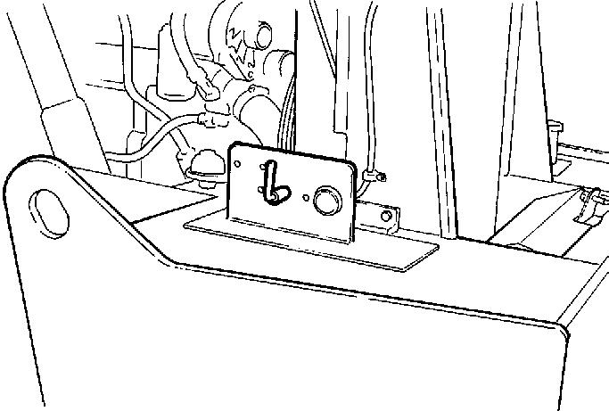
Lifting the roller
The machine’s gross weight is specified on the hoisting plate (1). Refer also to the Technical specifications.
Lifting equipment such as chains, steel wires, straps and lifting hooks must be dimensioned in accordance with the relevant safety regulations for the lifting equipment.
Stand well clear of the hoisted machine! Make sure that the lifting hooks are properly secured.
Unlocking the articulation
Remember to unlock the articulation before operating.
Fold the locking arm (1) back and secure it in the locking lug (4) with the locking stud (3). Insert the lowermost locking pin (2) fitted with a wire, to secure the locking stud (3). The locking lug (4) is located on the tractor frame.
Towing
The roller can be moved up to 300 meters (1,000 ft) using the instructions below.
Short distance towing with the engine running
Depress the emergency/parking brake knob and temporarily shut off the engine. Chock the drums to prevent the roller from moving
Turn both towing valves (1) (middle hexagonal nut) three turns counter clockwise, while holding the multifunction valve (2) (lowermost hexagonal nut) in place. The valves are placed on the forward drive pump.
Start the engine and allow it to idle.
The roller can now be towed and can also be steered if the steering system is otherwise functioning.
Step 2
Towing short distances where the engine is inoperative
Chock the drums to prevent the roller from moving when the brakes are mechanically disengaged. First release both towing valves as per alternative 1. Push in the button (1), and horizontal hunting the pump arm (2) when feeling resistance, then keep hunting the pump arm (2) several times until brake release.
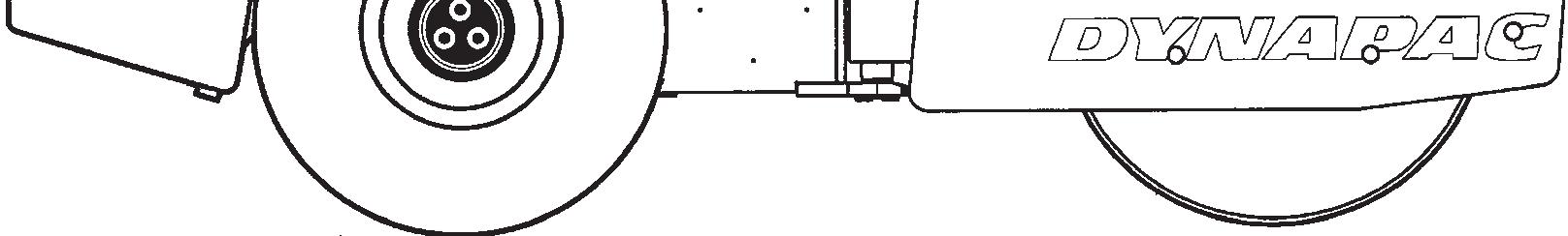
Towing the roller
When towing/recovering, the roller must be braked by the towing vehicle. A towing bar must be used as the roller has no brakes.
The roller must be towed slowly, max. 3 km/h (2 mph) and only towed short distances, max. 300 m (330 yards).
When towing/retrieving a machine, the towing device must be connected to both lifting holes. The pulling force must act longitudinally on the machine as shown in the figure. Maximum gross pulling force 308 kN (69241 lbf).
Restore (without towing): Step 1 and 2 on the preceding pages.
Roller prepared for transport
Lock the articulation before lifting and transporting. Follow the instructions under the relevant heading.
Chock the drums (1) and secure the chocks to the transport vehicle.
Block up under the drum frame (2), to avoid overload on the rubber suspension of the drum when lashing. Clamp down the roller with lashing strap at all four corners; decals (3) indicate the fixing points.
Remember to return the articulation to its unlocked position before starting the roller.
Operating instructions - Summary
Operating instructions - Summary

1.Follow the SAFETY INSTRUCTIONS specified in the Safety Manual.
2. Make sure that all instructions in the MAINTENANCE section are followed.
3. Turn the master switch to the ON position.
4. Move the forward/reverse lever to the NEUTRAL position.
5. Set the switch for Manual/Automatic vibration to the 0 position.
6. Set the engine speed control to idle.
7. Start the engine and allow it to warm up.
8. Set the engine speed control to the operating position.
9. Set the emergency/parking brake knob in the pulled-out position.
10.Drive the roller. Operate the forward/reverse lever with care.
11.Test the brakes. Remember that the braking distance will be longer if the roller is cold.
12. Use vibration only when the roller is in motion.
13.IN AN EMERGENCY:
- Push in the EMERGENCY/PARKING BRAKE KNOB
- Hold the steering wheel firmly.
- Brace yourself for a sudden stop.
14. When parking:
- Push in the reserve/parking brake knob.
- Stop the engine and chock the drum and wheels.
15. When lifting: - Refer to the relevant section in the Instruction Manual.
16. When towing: - Refer to the relevant section in the Instruction Manual.
17. When transporting: - Refer to the relevant section in the Instruction Manual.
18. When recovering - Refer to the relevant section in the Instruction Manual.
2018-8-24
4812313017-EN.pdf
ENGINE OIL
HYDRAULIC FLUID
Maintenance - Lubricants and symbols
Maintenance - Lubricants and symbols
Always use high-quality lubricants and the amounts recommended. Too much grease or oil can cause overheating, resulting in rapid wear.
Air temperature -15°C - +50°C (5°F-122°F)
P/N: 4812313753 (4 liters); 4812313754 (18 liters)
Air temperature -15°C-+40°C (5°F-104°F)
BIOLOGICAL HYDRAULIC FLUID
TRANSMISSION OIL
DRUM OIL
GREASE
P/N: 4812313760 (18 liters)
P/N: 4812313760 (18 liters)
Air temperature above +40°C (104°F)
BP Biohyd SE-S46
When it leaves the factory, the machine may be filled with biodegradable fluid. The same type of fluid must be used when changing or topping up.
Air temperature -15°C - +40°C (5°F-104°F)
P/N: 4812161879 (5 liters), 4812161880 (20 liters)
Air temperature 0°C (32°F) - above +40°C (104°F)
P/N: 4812161887
SKF LGHB2 (NLGI-Klass 2) or equivalent for the articulated joint. Dynapac Roller Grease; P/N: 4812030096 or equivalent for other grease points.
FUEL See engine manual.
COOLANT
Other fuel and lubricants are required when operating in areas with extremely high or extremely low ambient temperatures. See the ‘Special instructions’ chapter, or consult Dynapac.
2018-8-24
4812313017-EN.pdf
Maintenance - Lubricants and symbols
Maintenance symbols
Engine, oil level
Engine, oil filter
Hydraulic reservoir, level
Hydraulic fluid, filter
Transmission, oil level
Drum, oil level
Oil for lubrication
4812313017-EN.pdf
Tyre pressure
Air filter
Battery
Recycling
Fuel filter
Coolant, level
2018-8-24
Maintenance - Maintenance schedule
General

Periodic maintenance should be carried out after the number of hours specified. Use the daily, weekly etc. periods where number of hours cannot be used.
Remove all dirt before filling, when checking oils and fuel and when lubricating using oil or grease.
The manufacturer’s instructions found in the engine manual also apply.
Where both operational hours and time intervals are specified, maintenance should be carried out at the point in time that occurs first.
Every 10 hours of operation (Daily)
Refer to the contents to find the page number of the sections referred to !
After the FIRST 50 hours of operation
Refer to the contents to find the page number of the sections referred to !
Every 50 hours of operation (Weekly)
Refer to the contents to find the page number of the sections referred to!
Check that hoses and couplings are not leaking
4Inspect/clean the filter element in the air cleaner
8 Change the hydraulic fluid filter
17Lubricate the articulation 18
Lubricate the steering cylinder mounts
Check the wheel-nuts are tightened
Check the tire pressure
36Check the air conditioning
32Clean the coolers
36Check the air conditioner compressor belt
Every 250 hours of operation (Every three months)
Refer to the contents to find the page number of the sections referred to !
23Check the oil level in rear axle/planetary gearing
13Check oil level in drum gearbox
15Check oil level in drum cartridge
32Clean the coolers
20Check the bolted joints
24Check the bolted joints
16Check rubber elements and bolts joints
30Check battery
36Check the air c onditioning
The above applies to new or rec onditioned components only
The above applies to new or rec onditioned components only
3Change the fuel filter Refer to the engine manual
25Change the engine oil and oil filter Refer to the engine manual
Check the engine belt drive system Refer to the engine manual wheel nuts
2018-8-24
Every 500 hours of operation (Every six months)
Refer to the contents to find the page number of the sections referred to !
3Replace fuel pre-filter Refer t o t he engine manual
7Check bleeder filter on hydraulic reservoir
17Check st eering hitch
4Change main air filter element
Every 1000 hours of operation (Yearly)
Refer to the contents to find the page number of the sections referred to !
8Change t he hydraulic fluid filter
26Clean t he fuel t ank
22Change oil in rear axle cent ra l gea r redu cer
23Change oil in t he rear axle planetary gearing
33Check belt t ension for drive system Refer t o t he engine manual
35Replace t he fresh air filter in t he cab
12Change t he oil in t he drum cartridge
13Change t he oil in t he drum gearbox
37Lubricate t he Forward/Reverse lever
Every 2000 hours of operation (Every two years)
Refer to the contents to find the page number of the sections referred to !
9,10Change t he hydraulic fluid
36Overhaul air conditioning
Replace t he engine c oolant
4812313017-EN.pdf t o t he engine manual
2018-8-24
2018-8-24
Maintenance - 10h
Park the roller on a level surface. When checking and making adjustments, the engine should be switched off and the emergency/parking brake should be applied, if not otherwise specified.
Scrapers - Check, adjustment
It is important to consider movement of the drum when the machine turns, i.e., the scrapers can be damaged or wear of the drum may increase if adjustment is made closer than the values stated.
If necessary, adjust distance to the drum as follows:
Loosen the screws (2) on the scraper attachment. Then adjust the scraper blade (1) to 20 mm from the drum.
Tighten the screws (2).
Repeat the procedure for the other scraper blades (x4).
Scrapers, Pad-drum
Loosen the screws (1), then adjust each scraper tooth (2) to 20 mm between scraper tooth and drum.
Center each scraper tooth (2) between the pads.
Tighten the screws (1).
4812313017-EN.pdf
Soften scrapers (Optional)
Loosen the screws (2).
Then, adjust the scraper blade (1) so that it lightly touches the drum.
Tighten the screws (2).
Air circulation - Check
Ensure that the engine has free circulation of cooling air through the protective grille in the hood.
To open the engine hood, turn the locking arm (1) upward. Raise the hood to its fully open position, checking that the red safety catch on the left gas spring is latched.
If the engine's gas-springs are out of action and the hood is put at its upper position - block the hood so that it cannot fall.
4812313017-EN.pdf
2018-8-24
Coolant level - Check
Check that level of the coolant is between the max. and min. marks.
Take great caution if the radiator cap must be opened while the engine is hot. Wear protective gloves and goggles.
Fill with a mixture of 50% water and 50% anti freeze. See the lubrication specification in these instructions and in the engine manual.
Flush the system every other year and change the coolant. Make sure also that the air flow through the cooler is unobstructed.
Take care not to touch any hot parts of the engine or the radiator when removing the dipstick. Risk for burns.
The dipstick is located on the engine's right side. Pull up the dipstick (1) and check that the oil level is between the upper and lower marks. For further details, refer to the engine's instruction manual.
Refuel daily with diesel fuel up to the lower edge of the filler pipe (1). Follow the engine manufacturer's specification with regard to the quality of diesel fuel. Stop the engine. Short-circuit (press) the filler gun against a non-insulated part of the roller before refuelling, and against the filler pipe (1) while refuelling.
Never refuel while the engine is running. Do not smoke and avoid spilling fuel.
The tank holds 320 liters (84.5 gal) of fuel.
Hydraulic reservoir - Check fluid level
The sight glass is located on the right-hand side of the roller behind the operator's seat.
Place the roller on a flat surface and check the fluid level in the sight glass (1). If the level is too low, top up with the type of hydraulic fluid specified in the lubricant specification.
2018-8-24
Brakes - Check
Check the brakes by carrying out the following :
Drive the roller slowly forwards.
Turn the parking brake (1) to the right. The warning lamp (3) on the instrument panel should come on and the roller should stop.
After testing the brakes, set the forward/reverse lever (2) in neutral.
Pull up the emergency/parking brake knob.
The roller is now ready for operation.

Maintenance - 50h
Park the roller on a level surface. When checking and making adjustments, the engine should be switched off and the emergency/parking brake should be applied, if not otherwise specified.
Air cleaner
Checking - Change the main air filter
Change the air cleaner main filter when the warning lamp on the control panel comes on when the engine is running at maximum speed.
Release the clips (1), pull off the cover (2), and pull out the main filter (3).
Do not remove the backup filter (4).
Clean the air cleaner if necessary, see section Air cleaner - Cleaning.
When replacing the main filter (3), insert a new filter and refit the air cleaner in the reverse order.
Check the condition of the dust valve (6); replace if necessary.
When refitting the cover, make sure that the dust valve is positioned downwards.
1
Backup filter - Change
Change the backup filter with a new filter after every third replacement of the main filter.
To change the backup filter (1), pull the old filter out of its holder, insert a new filter and reassemble the air cleaner in the reverse order.
Clean the air cleaner if necessary, see section Air cleaner - Cleaning.
Air cleaner - Cleaning
Wipe clean the inside of the cover (2) and the filter housing (5). See the previous illustration.
Wipe also both surfaces for the outlet pipe; see adjacent figure.
Check that the hose clamps between the filter housing and the suction hose are tight and that the hoses are intact. Inspect the entire hose system, all the way to the engine.
2018-8-24
Do not allow anyone to remain in the vicinity of the steering joint when the engine is running. Risk of being crushed when the steering is operated. Press the emergency/parking brake knob before lubricating.
Turn the steering wheel fully to the left to gain access to all the steering system's lubricating nipples (7) on the right-hand side of the machine. Use grease as per the lubricant specification
Wipe off any dirt and grease from the nipples. Lubricate each nipple (1 and 2) with five strokes of a manual grease gun. Make sure that grease penetrates into the bearings.
If grease does not penetrate the bearings, it may be necessary to relieve the articulation joint with a jack while repeating the greasing process.
4812313017-EN.pdf
Steering cylinder - Lubrication
Wipe off any dirt and grease from the nipples.
Lubricate the nipples (3 and 4) with two strokes of a manual grease gun.
Turn the steering wheel fully to the right to gain access to the front lubricating nipple on the left steering cylinder and the lubricating nipple on the bearing cap. Allow some grease to remain on the nipples after lubrication. This prevents dirt from penetrating into the nipples.
Tires - Air pressure - Wheel nuts - Tightening
Check the tire pressures using a pressure gauge. If the tires are filled with fluid, the air valve (1) must be in the "12 o'clock" position during pumping.
Recommended pressure: See Technical Specifications.
Check the tire pressure.
When changing the tires it is important that both of them have the same rolling radius. This is necessary to ensure proper functioning of the anti-slip in the rear axle.
Check the tightening torque of the wheel nuts (2) at 660Nm oiled / 740 Nm dried.
Check both wheels and all nuts. (This only applies to a new machine or newly fitted wheels).
Check the safety manual that accompanies the roller before filling the tires with air.
4812313017-EN.pdf
2018-8-24
Air Conditioner (Optional) - Inspection
The system described in this manual is type Air Conditioner.
Never work under the roller when the engine is running. Park the roller on a level surface, chock the wheels and depress the parking brake control.
The drying filter is installed in the fluid reservoir.
With the unit in operation, open the engine hood and check using the sight glass (1) that bubbles are not visible on the drying filter.
Change the filter every year.
Clean the condensor element (1) located on the rear edge of the cab.
Hydraulic fluid filter - Replacement
Undo the cover/bleeder filter (2) on top of the reservoir so that over-pressure inside the reservoir can be eliminated.
Check that the bleeder filter (2) is not clogged, air must flow through the cap in both directions.
If passage in either direction is blocked, clean the filter with a little diesel oil and blow through with compressed air until the block is removed, or replace the cap with a new one.
Wear
2018-8-24
The filter element must be replaced when the maintenance indicator (1) turns red. The vehicle’s hydraulic system contains one high-pressure filter.
Unscrew the filter housing (2), remove the filter catridge and hand in to an environment-friendly waste disposal station.
Clean the filter housing. Insert the new filter cartridge. Replace the seal ring of the filter housing. Turn on the filter housing by hand, and tighten it using a belt wrench. Start the trial operation and check the tightness of the filter.
Replace the seal ring whenever the filter cartrdge is replaced.
After replacing the filter element, the red mark in the maintenance indicator (1) automatically reverts to green.
Apply a thin coat of fresh hydraulic fluid to the seal on the new filter. Screw tight the filter by hand. First tighten the filter until its seal is in contact with the filter attachment. Then turn an additional half revolution. Do not tighten the filter too hard as this could damage the seal.
Start the engine and check that there is no leakage of hydraulic fluid from the filter. Check level of fluid in the sight glass (3) and top up as required.
2018-8-24
Radiator - Check/Cleaning
The water and hydraulic fluid coolers can be accessed when the engine compartment cover is opened.
Make sure that the air flow through the coolers is unobstructed (1), (2) and (3).
Clean a dirty radiator using compressed air or a high-pressure water jet.
Blow air or direct water through the cooler in the opposite direction to that of the cooling air.
Be careful when using a high-pressure washerdo not place the nozzle too close to the radiator.
Wear protective goggles when working with compressed air or high-pressure water jets.
Air conditioning - Compressor belt (Optional) - Inspection
Inspect the condition of the compressor belt.
Check
4812313017-EN.pdf
Maintenance - 250h
Maintenance - 250h
Park the roller on a level surface. When checking and making adjustments, the engine should be switched off and the emergency/parking brake should be applied, if not otherwise specified.
Rear axle differential - Check oil level
Never work under the roller when the engine is running. Park on a level surface. Block the wheels securely.
Wipe clean and remove the level plug (1) and check that the oil level reaches the lower edge of the plug hole. Top off with oil to the right level if the level is low. Use transmission oil according to the lubricant specification.
Clean and refit the plug.
Position the roller so that the fill plug (1) in the planetary gear is at "12 o'clock", level plug (2) at "4 o'clock".
Wipe clean and remove the level plug (2) and check that the oil level reaches the lower edge of the plug hole. Top off with oil to the right level if the level is low. Use transmission oil. See lubrication specification.
Clean and refit the plug.
Check the fluid level in the same way on the rear axle's other planetary gear.
4812313017-EN.pdf
2018-8-24
Drum
- Checking the oil level
Position the drum so that the filler plug (2) is straight up.
Wipe clean the area around the level plug (1) and then undo the plug.
Ensure that the oil level reaches up to the lower edge of the plug hole.
Top off with oil to the right level if the level is low. Use transmission oil according to the lubricant specification. Clean and refit the plugs.
Wipe clean the filler plug (1) and level plug (3). Unscrew the filler plug (1).
Then loosen the level plug (3) on the underside of the cartridge and unscrew it until the hole in the middle of the plug becomes visible.
Top off with oil through the filler plug (1), until oil begins to run out from the level plug's (3) hole. The level is correct when it stops running.
Ensure that only MOBIL SHC 629 is used in the cartridges..
Do not overfill with oil - risk for overheating.
Clean and refit the plugs. Now repeat the procedure on the opposite side.
Drum cartridge - Cleaning the ventilation screw
Clean the drum's ventilation hole and ventilation screw (1), which’s right under the drum data plate. The hole is required to eliminate excess pressure inside the drum.
Radiator - Check/Cleaning
The water and hydraulic fluid coolers can be accessed when the engine compartment cover is opened. Make sure that the air flow through the coolers is unobstructed (1), (2) and (3).
Clean a dirty radiator using compressed air or a high-pressure water jet.
Blow air or direct water through the cooler in the opposite direction to that of the cooling air.
Be careful when using a high-pressure washerdo not place the nozzle too close to the radiator.
Wear protective goggles when working with compressed air or high-pressure water jets.
2018-8-24
Bolted joints - Checking tightening torque
Steering pump against engine (1) 38 Nm (28 lbf.ft).
Rear axle suspension (2) 330 Nm (243 lbf.ft), oiled.
Engine mounting (3). Check that all M12 bolts (x20) are tightened, 78 Nm (57 lbf.ft).
Wheel nuts (4). Check that all nuts are tightened, 630 Nm oiled.
(The above applies to new or replaced components only).
Rubber elements and fastening screws - Check
Check all rubber elements (1), replace all of the elements if more than 25% of them on one side of the drum are cracked deeper than 10-15 mm (0.4-0.6 in).
Check using a knife blade or pointed object.
Check also that the screw fasteners (2) are tightened.
Battery - Check electrolyte level
Never use a naked flame when checking the battery as the electrolyte emits explosive gas while the alternator is charging.
Open the engine cover and undo the quick-release screws (1).
Raise the battery cover (2).
Wipe the top of the battery. Wear safety goggles. The battery contains corrosive acid. Rinse with water if electrolyte comes into contact with the body.
4812313017-EN.pdf
Battery cell
If the ambient temperature is below freezing, run the engine for a while before topping off with distilled water. Otherwise the electrolyte might freeze. Make sure that ventilation holes in the cell cover are not clogged, then put the cover back on.
The cable shoes should be clean and well tightened. Clean corroded cable shoes and grease them with acid-free Vaseline.
Always disconnect the negative cable first when disconnecting the battery. When connecting the battery, always connect the positive cable first.
Discard used batteries wisely. Batteries contain lead, which is harmful to the environment.
Before doing any electric welding on the machine, disconnect the battery ground cable and then all electrical connections to the alternator.
Air conditioning - Inspection
Inspect refrigerant hoses and connections and make sure that there are no signs of an oil film that can indicate a refrigerant leakage.
2018-8-24
Fuel filter - Changing the fuel filter
The fuel filter is placed on the right side of the engine compartment.
Unscrew the fuel filter (1), then replace.
Diesel engine - Oil and Filter change
Take great care when draining warm fluid and oil. Wear protective gloves and goggles.
The oil plug (1) is most easily accessible from the underside of the engine, and is fitted with a hose on the tractor frame. Drain the oil when the engine is warm. Place a receptacle that holds 15 liters (4 gal) under the drain plug.
Change the engine oil filter at the same time. Refer to the engine manual.
Deliver the drained oil and filter to environmentally correct handling.
4812313017-EN.pdf
Maintenance
- Inspection
Inspect the condition of the engine drive belt.
See instruction manual for the engine.
Ensure good ventilation (air extraction) if the diesel engine is run indoors. Risk of carbon monoxide poisoning.
Tires the engine is running.
Stop the engine. Never inpect engine belt while the engine is running.
Check the tire pressures using a pressure gauge.
If the tires are filled with fluid, the air valve (1) must be in the "12 o'clock" position during pumping.
Recommended pressure: See Technical Specifications.
Check the tire pressure. When changing the tires it is important that both of them have the same rolling radius. This is necessary to ensure proper functioning of the anti-slip in the rear axle.
Check the tightening torque of the wheel nuts (2) at 660 Nm (Oiled) / 740 Nm (Dried).
Check both wheels and all nuts. (This only applies to a new machine or newly fitted wheels).
Check the safety manual that accompanies the roller before filling the tires with air.
4812313017-EN.pdf
2018-8-24
2018-8-24
Maintenance - 500h
Park the roller on a level surface. When checking and making adjustments, the engine should be switched off and the emergency/parking brake should be applied, if not otherwise specified.
Ensure that there is good ventilation (air extraction) if the engine is run indoors. Risk of carbon monoxide poisoning.
Bleeder filter - Inspection/Cleaning
If passage in either direction is blocked, clean the filter with a little diesel oil and blow through with compressed air until the block is removed, or replace the cap with a new one.
Always wear protective goggles when working with compressed air.
Check that the bleeder filter (2) is not clogged. Air should be able to pass through the cap unobstructed in both directions.
Start the engine and check that there is no leakage of hydraulic fluid from the filter. Check level of fluid in the sight glass (3) and top up as required.
1
Fuel pre-filter - Replace
Ensure good ventilation (air extraction) if the diesel engine is run indoors. Risk of carbon monoxide poisoning.
See instruction manual for the engine when replacing the filter, the chapter on the fuel system.
Steering hitch - Check
Inspect the steering hitch to detect any damage or cracks.
Check and tighten any loose bolts. Check also for any stiffness and play.
Air cleaner
- Change the main air filter
Change the air cleaner main filter when the warning lamp on the control panel comes on when the engine is running at maximum speed.
Release the clips (1), pull off the cover (2), and pull out the main filter (3).
Do not remove the backup filter (4).
Clean the air cleaner if necessary, see section Air cleaner - Cleaning.
When replacing the main filter (3), insert a new filter and refit the air cleaner in the reverse order.
Check the condition of the dust valve (6); replace if necessary.
When refitting the cover, make sure that the dust valve is positioned downwards.
4812313017-EN.pdf
2018-8-24
2018-8-24
Maintenance - 1000h
Park the roller on a level surface. When checking and making adjustments, the engine should be switched off and the emergency/parking brake should be applied, if not otherwise specified.
Ensure that there is good ventilation (air extraction) if the engine is run indoors. Risk of carbon monoxide poisoning.
Hydraulic fluid filter - Replacement
Undo the cover/bleeder filter (2) on top of the reservoir so that over-pressure inside the reservoir can be eliminated.
Check that the bleeder filter (2) is not clogged, air must flow through the cap in both directions.
If passage in either direction is blocked, clean the filter with a little diesel oil and blow through with compressed air until the block is removed, or replace the cap with a new one.
The filter element must be replaced when the maintenance indicator (1) turns red.
The vehicle’s hydraulic system contains one high-pressure filter.
Unscrew the filter housing (2), remove the filter catridge and hand in to an environment-friendly waste disposal station.
Clean the filter housing. Insert the new filter cartridge. Replace the seal ring of the filter housing. Turn on the filter housing by hand, and tighten it using a belt wrench. Start the trial operation and check the tightness of the filter.
Replace the seal ring whenever the filter cartrdge is replaced.
After replacing the filter element, the red mark in the maintenance indicator (1) automatically reverts to green.
Apply a thin coat of fresh hydraulic fluid to the seal on the new filter. Screw tight the filter by hand. First tighten the filter until its seal is in contact with the filter attachment. Then turn an additional half revolution. Do not tighten the filter too hard as this could damage the seal.
Start the engine and check that there is no leakage of hydraulic fluid from the filter. Check level of fluid in the sight glass (3) and top up as required.
Fuel tank - Drainage
Water and sediment in the fuel tank are removed via the drainage plug (1) in the bottom of the fuel tank. Be very careful during draining. Do not drop the plug or else all the fuel will flow out.
Drainage must be performed when the roller has been stationary for an extended period, e.g. after being stationary overnight. The fuel level should be as low as possible.
The roller should preferably have been standing with this side slightly lower, so that water and sediment have gathered near the drainage plug (1).
Save the condensate and sediment and hand it in to an environment-friendly waste disposal station.
Drain as follows:
- Place a container under the plug (1).
- Remove the plug (1).
- Drain out the condensate and sediment until only pure fuel emerges at the plug.
- Screw in the plug again.
2018-8-24
Air conditioning (Optional)
Fresh air filter - Change
Use a step ladder to reach the filter (1). The filter can also be accessed via the right cab window.
Loosen the screws on the cab's right side. Take down the whole holder and remove the filter insert.
Replace with a new filter.
It may be necessary to change the filter more often if the machine is working in a dusty environment.
Rear axle central gear reducer - Oil change
Never work under the roller when the engine is running. Park on a level surface. Block the wheels securely.
Wipe clean and remove the level/filler plug (1) and all three drain plugs (2) and drain the oil into a suitable receptacle. The volume is approximately 14 liters (14.8 qts).
Save the oil and dispose of it in an approved manner.
Refit the drainage plugs and top up with fresh oil until the correct level is reached. Refit the level/filler plug. Use transmission oil, see Lubricant Specification.
Maintenance - 1000h
Oil can be filled through plug (2) at 12 o’clock (filling position) with suitable volume for each side. And oil level can be checked through oil level hole (3). Wipe clean, unscrew the plug (2) (when the plug is at 6 o’clock) and drain the oil into a suitable receptacle.
Plug (1) which for central oil filling, oil level can be shown from oil level hole (4), unscrew drainage plug (5) to drain the oil.
The plug (6) on the central reducer at 6 o’clock is for oil drainage.
After filling three filling portals. Oil arrives at all gear meshing position by oil transmission.
Fill with oil to lower edge of level hole. Use transmission oil. See the lubrication specification. Clean and refit the plug.
Check the fluid level in the same way on the rear axle's other planetary gear.
Oil should be taken to your local waste disposal station.
Check the brake cylinder through checking hole (7).
To release brake by using option port (8).
4812313017-EN.pdf
2018-8-24
Drum cartridge - Oil change
Position the machine level so that the indicator pin (1) on the inside of the drum is aligned with the top of the drum frame.
Place a receptacle for about 5 liters (1.32 gal) underneath the drain plug (2).
Save the oil and hand in to an environment-friendly waste disposal station.
Clean and unscrew the filler plug (1) and the drain plug (2).
Allow all the oil to run out. Fit the drain plug and fill with new synthetic oil in accordance with the instructions under "Drum cartridge - checking the oil level".
Repeat the procedure on the opposite side.
Ensure that only MOBIL SHC 629 is used in the cartridges..
Drum gearbox - Oil change
Place the roller on a level surface with the plugs (2) and (3) as illustrated.
Wipe clean, unscrew the plugs (1, 2 and 3) and drain the oil into a suitable receptacle, capacity about 3.5 liters (1 gal.).
Refit the plug (3) and fill with oil up to the level plug (1), according to "Drum gearbox - Checking the oil level".
Use transmission oil according to the lubricant specification.
Clean and refit the level plug (1) and filler plug (2).
Controls - Lubrication
Lubricate the forward/reverse lever's mechanical mechanism. Remove the protective cover (1) by undoing the screws (2). Lubricate the mechanism with oil.
Check and tighten any loose bolts. Refit the protective cover.
Maintenance - 2000h
Park the roller on a level surface. When checking and making adjustments, the engine should be switched off and the emergency/parking brake should be applied, if not otherwise specified.
Ensue that there is good ventilation (air extraction) if the engine is run indoors. Risk of carbon monoxide poisoning.
Take great care when draining fluids and oils. Wear protective gloves and goggles.
Place a receptacle that holds at least 60 liters (15.9 gal)) beside the roller.
Unscrew the drainage plug (1).
Open the stock cock and allow the oil to run through a hose to the drainage receptacle.
Refit the plug.
Deliver the drained fluid to environmentally correct handling.
Fill with fresh hydraulic fluid. Refer to the lubricants specification for grade information.
Change the hydraulic fluid filter as described under the heading 'Every 1000 hours of operation'.
Start the engine and operate the hydraulic functions. Check the level in the reservoir and top off as required.
Automatic Climate Control - Overhaul
Regular inspection and maintenance are necessary to ensure satisfactory long-term operation.
Clean all dust from the condenser element (1) using compressed air. Blow from above downwards. The air jet can damage the element flanges if it is too powerful.
2018-8-24
Coolant - Replace
Clean all dust from the cooling unit and the cooling element (1) using compressed air.
Check the system hoses for chafing. Make sure that drainage from the cooling unit is unobstructed so that no condensation accumulates inside the unit.
Drain by pinching the valves (2), re-fill new coolant.
Refer Engine Manual for replacement.
Drying filter - Check
With the unit in operation, open the engine hood and check using the sight glass (1) that bubbles are not visible on the drying filter. If bubbles are visible through the sight glass, it is a sign that the refrigerant level is too low. If so, stop the unit. The unit may be damaged if it is run with insufficient refrigerant. We recommend to change the dryer filter once a year. with too little refrigerant.
Do not disconnect or undo the hose couplings.
The cooling system is pressurized. Incorrect handling can result in serious personal injury.
The system contains pressurized refrigerant. It is forbidden to release refrigerants into the atmosphere. Work on the refrigerant circuit is only to be carriedd out by authorized companies.
Compressor - Check (Optional)
The unit should, if possible, be run at least five minutes every week to ensure the lubrication of the gaskets and compressor in the system.
Check the V-belt (2) for any physical damage or cracks.
The air conditioning unit should not be run when the outdoor temperature is below 0 C, other than for the above.
