5 minute read
Maintenance – Annually


8.8.2 Checking, adjusting the valve clearance
Perform this maintenance work at the latest after 250 operating hours
NOTICE!
Danger of engine damage!
We recommend to have this work carried out by trained personnel or our after sales service.
–Before checking the valve clearance let the engine cool down.
Preparations
Protective equipment: n Working clothes n Protective gloves
1. Park the machine in secured condition ÄChapter 6.5 ‘Parking the machine in secured condition’ on page 61
2. Let the engine cool down to 20 °C (68 °F).
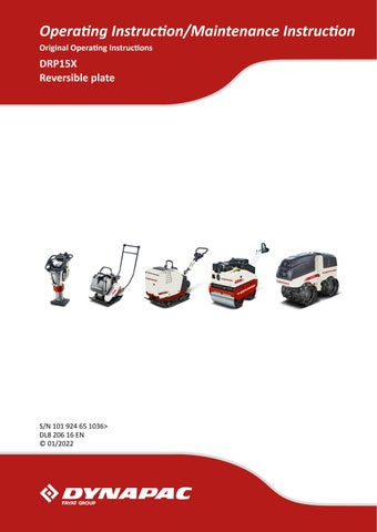
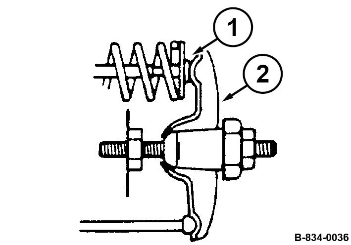
3. Unscrew the fastening screws (1).
4. Remove valve cover (2) with seal (3).
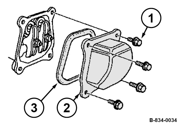
5. Set the piston to the top dead centre position of the compression stroke.
For this purpose align the alignment mark (2) on the starter disc to the top bore (1).
Checking the valve clearance
1. Check the valve clearance with a feeler gauge between rocker arm (2) and valve shaft (1) on both valves, adjust if necessary.
Adjusting the valve clearance
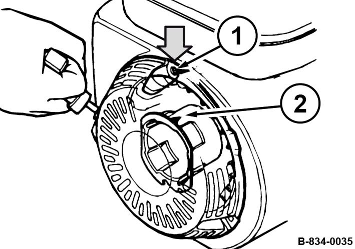
1. Hold the hexagon nut (1) on the rocker arm and loosen counter nut (2).
2. Adjust the hexagon nut, until the feeler gauge can be inserted and pulled out with little resistance after retightening the counter nut.
Final work
1. Install the valve cover (2) with a new seal (3).
2. Tighten the fastening screws (1) evenly.
3. After a short test run, check the engine for leaks.
8.8.3 Cleaning the slurry filter and fuel strainer
DANGER!
Danger to life caused by explosive gas-air mixes!
–Do not allow gasoline to come into contact with hot components.
–Smoking and open fire is prohibited.
–Keep away from heat sources, sparks and other sources of ignition.
–Do not spill any gasoline.
Protective equipment: n Working clothes n Safety shoes n Protective gloves
1. Park the machine safely ÄChapter 6.5 ‘Parking the machine in secured condition’ on page 61
2. Allow the engine to cool down.
3. Close the fuel valve.
B-HON-0036
4. Disassemble filter bowl (3), O-ring (2) and filter (1).
5. Clean filter bowl and filter in a non-inflammable solvent, dry them thoroughly afterwards.
B-HON-0040
6. Open the fuel valve and collect running out fuel.
7. Close the fuel valve.
8. Check the O-ring (2) for damage, replace if necessary.
9. Install the filter (1).
Observe the alignment (A) of the filter on the housing.
10. Assemble the filter bowl (3) with the O-ring.
8.8.4 Replacing the air filter
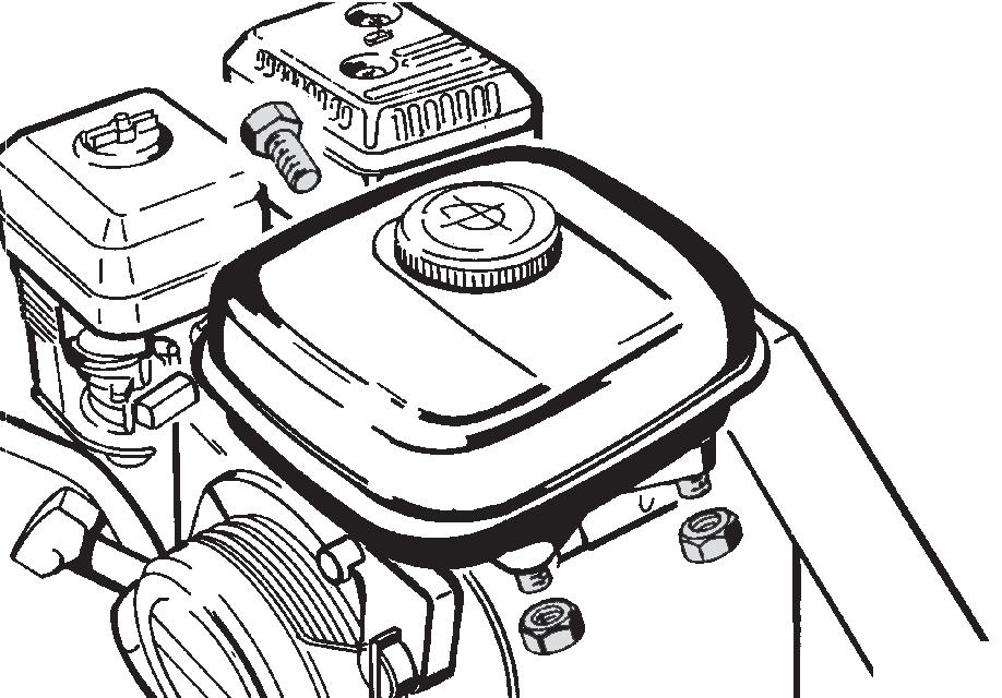
12. Loosen the hose clamp (1) and pull off the fuel hose.
13. Unscrew the fuel strainer (3) with the seal (2).
14. Clean the fuel strainer, check the condition of the screen, replace if necessary.
15. Turn the fuel strainer tightly in with the new seal.
16. Assemble the fuel hose with the hose clamp.
17. Assemble the fuel tank with hexagon nuts (2) and hexagon screw (1).
18. Check the fuel system for leaks.
19. Dispose of fuel and replaced components in an environmentally friendly way.
NOTICE!
Danger of engine damage! –Do not start the engine after having removed the air filter.
Protective equipment: n Working clothes n Safety shoes n Protective gloves
1. Park the machine safely ÄChapter 6.5 ‘Parking the machine in secured condition’ on page 61
2. Allow the engine to cool down.
3. Unscrew wing nut (1) and remove cover (2).
4. Clean the cover.
5. Unscrew wing nut (3) and remove filter element (4).
6. Check the rubber seal (5), replace if necessary.
The rubber seal frequently sticks to the filter element.
7. Replace paper element and foam element.
NOTICE!
Danger of engine damage!
–Prevent dirt from getting into the air intake opening.
–Do not clean the air filter housing with compressed air.
8. Clean the filter housing with a clean, lint-free cloth.
9. Pull the foam rubber element over the paper element.
NOTICE!
Danger of engine damage! –Insert the filter element correctly.
10. Install the rubber seal (5).
11. Insert the filter element (4) correctly and fasten it with the wing nut (3).
12. Fasten the cover (2) with the wing nut (1).
13. Dispose of the old filter element in an environmentally friendly way.
Maintenance – Annually
8.8.5 Replacing the V-belt
Protective equipment: n Working clothes n Safety shoes n Protective gloves
Tool: n Locking lever for V-belt pulley ð Nominal value: 317 ± 1 mm (12.5 ± 0.04 in)
We recommend using the locking lever to unscrew and screw on the V-belt pulley. The locking lever prevents the V-belt pulley from turning during work. The screws and nuts are not included in the scope of delivery.
1. Park the machine safely ÄChapter 6.5 ‘Parking the machine in secured condition’ on page 61.
2. Allow the engine to cool down.
3. Unscrew the V-belt guard (1).
4. Remove the guard plate.
5. Insert two M8 screws according to the required hole spacing and tighten them with two M8 nuts.
6. Insert the locking lever into the V-belt pulley.
7. Unscrew the V-belt pulley (1).
8. Replace the V-belt (3).
9. If necessary, reassemble the spacers (2) that may have been removed.
10. Position the V-belt pulley and screw in the screws.
11. Insert the locking lever into the V-belt pulley and tighten the V-belt pulley, tightening torque: 35 Nm (26 ft lbf).
12. Check the centre distance (x) between the centrifugal clutch (1) and the V-belt pulley (2).
If the centre distance is incorrect, contact our customer service.
13.
8.8.5.1 Checking the frequency of the base plate
Keep feet and hands clear of the vibrating base plate.
CAUTION!
Danger of injury caused by uncontrolled machine movement!
–Always hold on to a running machine.
–Always keep an eye on a running machine.
Protective equipment: n Working clothes n Hearing protection n Safety shoes
Tool: n Sirometer ð Nominal value: ÄChapter 2 ‘Technical data’ on page 11
1. Park the machine on a rubber mat.
2. Start the engine ÄChapter 6.2 ‘Starting the engine’ on page 55.
3. Run the machine at maximum speed for one minute.
4. Check the base plate’s frequency with a suitable measuring instrument (e.g. Sirometer).
5. Park the machine safely ÄChapter 6.5 ‘Parking the machine in secured condition’ on page 61
8.8.6 Replacing the starter rope
6. If frequency incorrect: n Check the engine speed. n Check the V-belt. n If necessary, contact our customer service.
Protective equipment: n Working clothes n Safety shoes n Protective gloves
1. Park the machine safely ÄChapter 6.5 ‘Parking the machine in secured condition’ on page 61
2. Allow the engine to cool down.
3. Disassemble the recoil starter.
4. Сompletely pull out the starter rope with the starter handle.

5. If the starter rope is broken or the coil is swivelled back: n Before installing the rope, turn the coil (3) 5 turns anticlockwise and align the rope openings (2) with the coil and housing (1).
6. Secure the coil against unwinding. To do this, secure the coil (3) and housing (1) with a suitable means ( e.g. cable tie) (2).
7. Loosen the knots of the starter rope at both ends and remove the old starter rope.
8. Thread in the new starter rope (4) and fasten it at both ends with appropriate knots.
9. CAUTION!
Danger of injury caused by the starter handle hitting against your body! –Do not let the starter handle hit back.
Remove the fastening of the coil and slowly return the starter handle to the starting position.
10. Test the function and ease of movement of the recoil starter by pulling the starter handle.
11. Assemble the recoil starter.
B-834-0040
8.8.7 Changing the oil in the exciter housing
NOTICE!
Components may get damaged!
–Use only oil of the permitted specification ÄChapter 8.3 ‘List of fuels and lubricants’ on page 74.
Protective equipment: n Working clothes n Safety shoes n Protective gloves
1. Drive the machine onto horizontal, level, firm ground.
2. Park the machine safely ÄChapter 6.5 ‘Parking the machine in secured condition’ on page 61.
3. Clean the area around the bleeding screw (1) and filling/drain plug (2).
4. Tilt the machine slightly towards the oil drain side and secure it properly.
5. Unscrew the bleeding screw.
6. Unscrew the filling/drain plug and collect any oil running out.