6 minute read
Operation - Vibration
Operation - Vibration
Activation/deactivation of the vibration is selected with the switch (20).
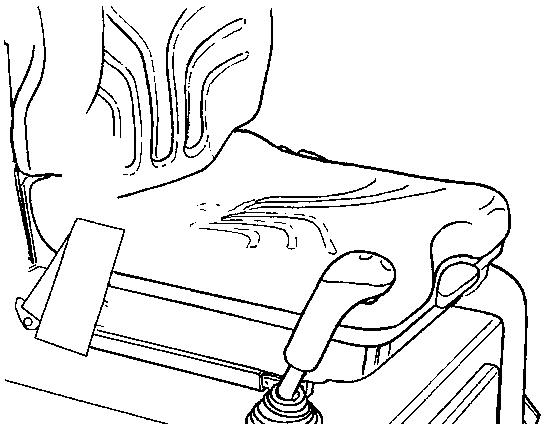
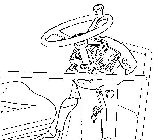
The operator must activate the vibration via the switch (4) on the underside of the forward/reverse handle. See illustration below.
Vibration - Activation
Never activate vibration when the roller is stationary. This can damage both the surface and the machine.
Engage and disengage vibration using the switch (4) on the underside of the forward/reverse lever.
Always switch off vibration before the roller comes to a standstill.
ICA134-3EN2.pdf
2012-04-13
Operating - Stopping
Braking
Emergency braking
Braking is normally activated using the forward/reverse lever. The hydrostatic transmission brakes the roller when the lever is moved towards the neutral position.
There is also a brake in the drum motor and rear axle that acts as an emergency brake during operation. For emergency braking, press the emergency stop (3), hold the steering wheel firmly and be prepared for a sudden stop. The brakes are applied and the engine stops.
After emergency braking, return the forward/reverse lever to neutral position and pull out the emergency stop (3). When the roller is fitted with an Interlock it is necessary to sit down in the driver seat to restart the engine.
Normal braking
Press the switch (4) to switch off the vibration. Move the forward/reverse lever (6) to the neutral position to stop the roller.
Set the speed control (2) to idling position: Low. Set the parkering brake switch (31) in the On position.

Always use the parking brake (31) when the machine is stationary on a sloping surface.

When starting and driving a machine that is cold, remember that the hydraulic fluid is also cold and that braking distances can be longer than normal until the machine reaches the working temperature.
ICA134-3EN2.pdf
Switching off
Check instruments and warning lamps to see if any faults are indicated. Switch off all lights and other electrical functions.
Turn the starter switch (1) to the left to switched off position 1. At the end of the shift, lower the instrument cover (22) and lock it.


Parking
Chocking the drums
Never disembark from the roller when the engine is running without pressing the parking brake.
Make sure that the roller is parked in a safe place with respect to other road users. Chock the drums if the roller is parked on sloping ground.
2012-04-13
Master switch
Before leaving the roller for the day, switch the master switch (1) to the disconnected position and remove the handle.
This will prevent the battery discharging and will also make it difficult for unauthorized persons to start and operate the machine. Also lock the hood to the engine compartment.
2012-04-13
Long-term parking
The following instructions should be followed when long term parking (more than one month).
These measures apply when parking for a period of up to 6 months.
Before re-commissioning the roller, the points marked with an asterisk * must be returned to the pre-storage state.
Wash the machine and touch up the paint finish to avoid rusting.
Treat exposed parts with anti-rust agent, lubricate the machine thoroughly and apply grease to unpainted surfaces.
Engine
* Refer to the manufacturer’s instructions in the engine manual that is supplied with the roller.
Battery
* Remove the battery from the machine, clean, grease the cable connectors (terminals) and trickle charge the battery once a month. The battery is otherwise maintenance free.
Air cleaner, exhaust pipe
* Cover the air cleaner (see under the heading 'Every 50 hours of operation' or 'Every 1000 hours of operation') or its opening with plastic or tape. Also cover the exhaust pipe opening. This is to avoid moisture entering the engine.
Fuel tank
Fill the fuel tank completely full to prevent condensation.
Hydraulic reservoir
Fill the hydraulic reservoir to the uppermost level mark (see under the heading ‘Every 10 hours of operation.’)
Tires
Check that the tire pressure is 200 kPa (2,0 kp/cm2).
ICA134-3EN2.pdf
Hoods, tarpaulin
* Lower the instrument cover over the instrument panel.
* Cover the entire roller with a tarpaulin. A gap must be left between the tarpaulin and the ground.
* If possible, store the roller indoors and ideally in a building where the temperature is constant.
Steering cylinder, hinges, etc.
Grease the steering cylinder piston with conservation grease.
Grease the hinges on the doors to the engine compartment. Grease both ends of the forward/reverse control (bright parts) (see under the heading ‘Every 500 hours of operation’).
2012-04-13
Miscellaneous Lifting
Locking
Articulation must be locked to prevent inadvertent turning before lifting the roller.
Turn the steering wheel to the straight ahead position. Push in the emergency/parking brake knob.
Pull out the locking pin (2) fitted with a wire, and pull up the stud (3).
Fold out the locking arm (1) and place it over the locking lug (4) on the drum frame.
Fit the locking stub (3) in the holes through the locking arm (1) and locking lug (4) and secure the stud in position with the locking pin (2).
Lifting the roller
The machine's gross weight is specified on the hoisting plate (1). Refer also to the Technical specifications.
Lifting equipment such as chains, steel wires, straps and lifting hooks must be dimensioned in accordance with the relevant safety regulations for the lifting equipment.
Stand well clear of the hoisted machine! Make sure that the lifting hooks are properly secured.
Unlocking the articulation
Remember to unlock the articulation before operating. Fold the locking arm (3) back and secure it in the locking lug (4) with the stud (3). Insert the locking pin (2) fitted with a wire, to secure the stud (3). The locking lug (4) is located on the tractor frame.

Towing
The roller can be moved up to 300 meters (1,000 ft) using the instructions below.
Alternative 1
Short distance towing with the engine running Depress the emergency/parking brake knob and temporarily shut off the engine. Chock the drum and tires to prevent the roller from moving
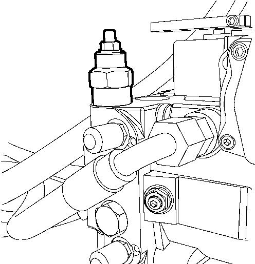
Unscrew both lock nuts (2) and carefully screw in the adjusting bolts (1) until they stop. Now turn the adjusting bolts (1) an additional half turn to open the valves. The valves are located on the propulsion pump. Start the engine and allow it to idle.
The roller can now be towed and can also be steered if the steering system is otherwise functioning.
2012-04-13
Alternative 2
Towing short distances where the engine is inoperative
Chock the drum and tires to prevent the roller from moving when the brakes are mechanically disengaged.
Rear axle brake
The two brake release screws (1) are located on the front and back of the rear axle.
Brake disengagement
Unscrew the brake release screws (1) and remove the stop washers (3). The screws must not be completely removed, only unscrewed enough to remove the washers.
Now tighten the brake release screws (1) alternately until they are fully screwed in.
The brake is now disengaged.
Releasing the drum brake
Drum motor brake
Remove the drum brake's center plug (2) which can be accessed through the center hole (1) in the left frame side.
Screw in the bolt (3) all the way as shown in the figure. Now screw in the nut (4) so that it is flush with the washer, and then an additional 0.5 - 0.75 turns, holding the screw in place (3).
The brake is now disengaged and the machine can be towed.
Reset the drum motor brake after towing.
2012-04-13
2012-04-13
Towing the roller
When towing/recovering, the roller must be braked by the towing vehicle. A towing bar must be used as the roller has no brakes.
The roller must be towed slowly, max. 3 kp/h (2 mph) and only towed short distances, max. 300 m (330 yards).
When towing/retrieving a machine, the towing device must be connected to both lifting holes. The pulling force must act longitudinally on the machine as illustrated. Maximum gross pulling force 75 kN (16860 lbf).
Restore the items for towing according to alternative 1 or 2 on the preceding pages.
Roller prepared for transport
Lock the articulation before lifting and transporting. Follow the instructions under the relevant heading.
Do not use fastening devices over the articulation.
Chock the drums (1) and secure the chocks to the transport vehicle.
Block up under the drum frame (2), to avoid overload on the rubber suspension of the drum when lashing.
Clamp down the roller with lashing strap at all four corners; decals (3) indicate the fixing points. Remember to return the articulation to its unlocked position before starting the roller.
ICA134-3EN2.pdf
Operating instructions - Summary
1.Follow the SAFETY INSTRUCTIONS specified in the Safety Manual.
2. Make sure that all instructions in the MAINTENANCE section are followed.
3. Turn the master switch to the ON position.
4. Move the forward/reverse lever to the NEUTRAL position.
5. Set the vibration switch in position 0.
6. Set the engine speed control to idle (900 rpm).
7. Set the emergency stop in the pulled out position.
8. Start the engine and allow it to warm up.
9. Set the engine speed control to the operating position (2870 rpm).
10.Drive the roller. Operate the forward/reverse lever with care.
11.Test the brakes. Remember that the braking distance will be longer if the roller is cold.
12. Use vibration only when the roller is in motion.
13.IN AN EMERGENCY:
- Press the emergency stop
- Hold the steering wheel firmly.
- Brace yourself for a sudden stop.
14. When parking:
- Press the emergency stop.
- Chock the drum and wheels.
15. When lifting: - Refer to the relevant section in the Instruction Manual.
16. When towing: - Refer to the relevant section in the Instruction Manual.
17. When transporting: - Refer to the relevant section in the Instruction Manual.
18. When recovering - Refer to the relevant section in the Instruction Manual.
2012-04-13
ICA134-3EN2.pdf
2012-04-13


