5 minute read
Machine description - Instruments/Controls
NoDesignation Symbol Function
17.Hazard beacon, switch (Optional)
18.Direction indicators, switch (Optional)
19.Horn, switch
20.Vibration, switch
21.Strike-off blade, On/Off, switch (Optional)
22.Control panel
23.Warning lamp, low fuel level
24.Warning lamp, oil pressure
25.Warning lamp, parking brake
Where depressed, the hazard beacon is on
When depressed to the left, the left direction indicators are on etc. In the middle position the function is shut off.
Press to sound the horn.
Activates the vibration together with the switch in the forward/reverse lever.
When pressed, the strike-off blade is activated.
The lamp comes on when the fuel level in the tank is low.
This lamp lights if the lubricating pressure in the engine is too low. Stop the engine immediately and locate the fault.
The lamp lights when the parking brake is activated.
26.Fuel level Shows the fuel level in the diesel tank.
27.Warning lamp, water temperature
28.Warning lamp, battery charging
29.Warning lamp, glow plug
30.Hourmeter
31.Parking brake On/Off, switch
32.Motor diagnostics
33.Motor diagnostics
The light comes on if the water temperature is too high.
If the lamp lights while the engine is running the alternator is not charging. Stop the engine and locate the fault.
The lamp must go out before the starter switch is moved to position 3c for activation of the starter motor.
Shows the number of hours the engine has run.
Push in to activate the parking brake, the machine stops with the engine running. Always use the parking brake when the machine is stationary on a sloping surface.
Control lamp red. Serious fault: Turn the motor off at once! Attend to before restarting.
Control lamp yellow. Less serious fault: Attend to as soon as possible.
ICA134-3EN2.pdf
2012-04-13
Fuses in the
Machine description - Electrical system
Machine description - Electrical system
Fuses
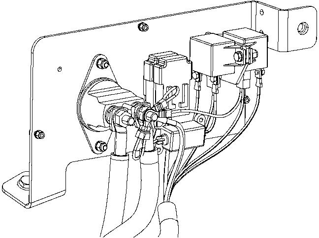
The figure shows the position of the fuses.
The table below gives fuse amperage and function. All fuses are flat pin fuses.
The machine is equipped with a 12V electrical system and an AC alternator.
Main fuses
There is one main fuse (2). It is located behind the battery master switch. The three screws need to be unscrewed to remove the plastic cover.
The fuse if of the flat pin type.
The starter relay (1), preheating relay (3) and fuse for the preheating relay (4) are also fitted here.
Supply standard
Supply lighting *
40A(Orange)
20A(Yellow)
Power supply, preheater100A(Blue)
* Optional equipment
2012-04-13
ICA134-3EN2.pdf
Machine description - Electrical system
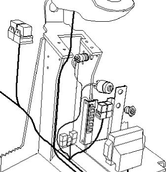
The control unit (ECU) (1) is located behind the cover (2) under the operator seat.
This control unit looks after the electrical drive control, including vibration, start-stop.
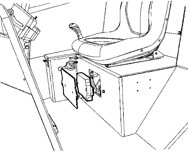
Operation - Starting
Before starting
Master switch - Switching on
Remember to carry out daily maintenance. Refer to the maintenance instructions.
The master switch is located in the engine compartment. Turn the key (1) to the on position. The entire roller is now supplied with power.
The engine hood must be closed by unlocked when operating, so that the battery voltage can be quickly disconnected if necessary.
Operator’s seat - Adjusting
Adjust the operator’s seat so that the position is comfortable and so that the controls are within easy reach.
The seat can be adjusted lengthways (1).
Instruments and lamps - Checking
Make sure that the emergency stop (2) is pulled out. When the roller is in neutral or there is no load on the operator seat, the automatic brake function is engaged.
Pull out the emergency stop (2).
Turn the switch (1) to position 3a.
Check that the warning lamps in the warning panel (22) come on.
If a ROPS (2) (Roll Over Protective Structure) is fitted on the roller, always wear the seat belt (1) provided and wear a protective helmet.
Replace the seat belt (1) if it shows signs of wear or has been subjected to high levels of force.
Check that the rubber elements (3) on the platform are intact. Worn elements will impair comfort.
Ensure that the anti-slip (4) on the platform is in good condition. Replace where anti-slip friction is poor.
2012-04-13
Interlock
The roller is equipped with Interlock.
If you stand up from the operator's seat when the forward/reverse lever is in the drive position, the machine stops and the diesel engine is switched off after 3 seconds. Brace yourself for a sudden stop.
Interlock is not activated if the forward/reverse lever is in neutral.
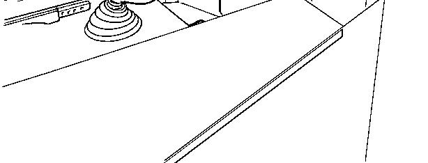
If the emergency stop is activated the diesel engine will stop.
Make sure that the emergency stop (3) is pulled out. Set the forward/reverse lever (6) in neutral. The engine can only be started when the lever is in neutral.
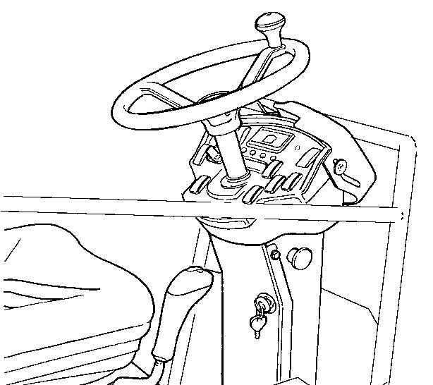
Turn the vibration switch (20) to the Off position (position O).
In the event of high external temperature, set the speed control (2) in idling position: Low.
Preheating: Turn the key to position II. When the glow lamp (29) goes off, after about 10 seconds, turn the starter switch (1) to position 3c. Release the starter as soon as the engine has started.
Do not run the starter motor for too long. If the engine does not start, wait a minute or so before trying again.
Idle the engine for a few minutes until it is warm, longer if the ambient temperature is below +10 °C (50 °F)
At temperatures below 0°C (32°F) the diesel engine and hydraulic system should be warmed up for at least 15 minutes.
ICA134-3EN2.pdf
Check while warming the engine that the warning lamps for the oil pressure (24) and charging (28) go out.
The warning lamp (25) should remain on.
When starting and driving a machine that is cold, remember that the hydraulic fluid is also cold and that braking distances can be longer than normal until the machine reaches the working temperature.
Ensure that there is good ventilation (air extraction) if the engine is run indoors. Risk of carbon monoxide poisoning.
Strike-off blade (Optional)
Ensure always that the strike-off blade is secured by the locking pins (1) when driving with the blade in its raised position. Always lower the blade to the ground before leaving or parking the roller.
2012-04-13
Operation - Driving
Operating the roller
Under no circumstances is the machine to be operated from the ground. The operator must be seated inside the machine during all operation.
Set the speed control (2) in working position: High. Check that the steering is working correctly by turning the steering wheel once to the right and once to the left while the roller is stationary.
Make sure that the area in front of and behind the roller is clear.
Carefully move the forward/reverse lever (6) forwards or backwards, depending on which direction of travel is required.
The speed increases as the lever is moved away from the neutral position.
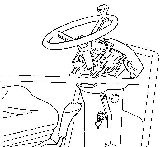
The speed should always be controlled by using the forward/reverse lever, and never by changing the engine speed.
Test the emergency stop by pressing the emergency stop button (3) while the roller is moving slowly forward. Brace yourself for a sudden stop. The engine will be switched off and the brakes activated.
Check while driving that the warning lamps have not gone on.
ICA134-3EN2.pdf
Operating
Before driving, make certain that the blade is in its uppermost position (raised). Inspect the condition of the ground before using the blade.
The Joystick (1) has five positions. Middle - Neutral position. Reverse - Lifting the blade. Forward - Lowering the blade. Tilting - Right/Left (Option)
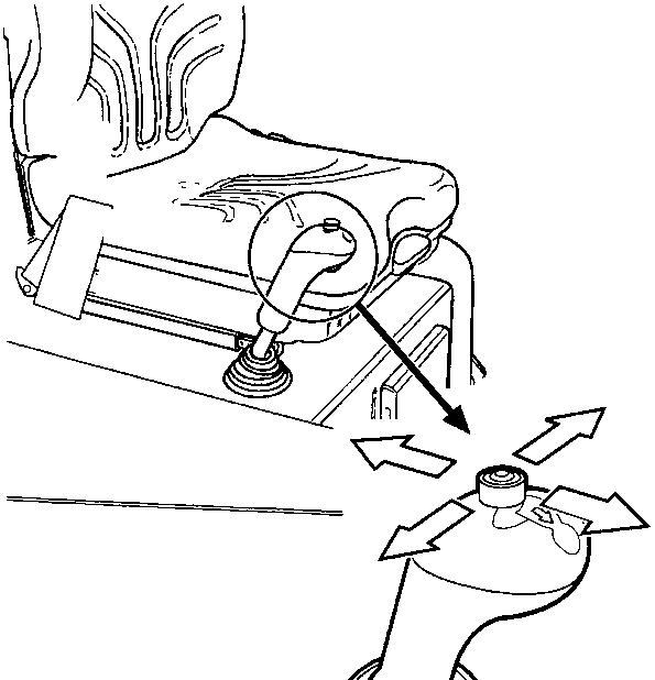
Lower the blade to the ground before leaving or parking the roller. Use the blade only when driving FORWARD.
2012-04-13


