4 minute read
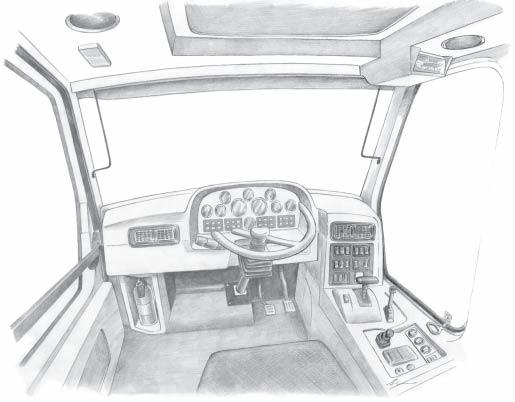
Controls


Standard extra equipment and optional accessories are also shown and described.
54 55 56 57 58 59 60
61 62 63 65 64
PosDescription Page
54Column switch 60 55Steering wheel 56Steering column 62 57Brake pedal 63 58Throttle pedal (accelerator) 63 59Gear selector 64 60Tip control lever 65 61Parking brake lever 65 62Starter switch 65 63Cigarette lighter 66 64Emergency exit 66 65Cab ventilation 67
A B
C
54.Column switch 16*
The column switch is a multi-function switch for main lights, horn, direction indicators and windscreen wiper/washer.
Main lights (A, B, C): A.Low beam (when switch 35 is in position 2) B.High beam (when switch 35 is in position 2), indicator 29 will light. C.High beam flash. Automatic return.
D.Horn, centre button automatic return.
E
F
E.Right turn, all right direction indicators flash.
Indicator light 32 flashes correspondingly. F.Left turn. All left direction indicators flash.
Indicator light 32 flashes correspondingly.
G
H
G.Windscreen wiper. Turn handle. Positions: 0OFF
Jinterval
I low speed IIhigh speed
H.Windscreen washer, push outer ring to activate the washer motor. At the same time, the wiper wipes some times after releasing the ring.
56.Steering column
The steering wheel is fitted on an adjustable column for comfortable reach and easy operation.
•Height adjustment - lift lever up to unlock.
•Tilt adjustment - push lever down to unlock.
•Confirm that the steering column is fixed before operating the truck.
WARNING
Do not adjust position while driving!
57.Brake pedal
The pedal controls the main brake (service brake). When depressing the pedal, the rear stop light will light. Braking effect depends on pedal position. Depress pedal gradually, and learn to associate braking requirements for loaded and unladen dump truck. Do not use the pedal for long period retardations, i.e. loaded downhill. This will overheat and damage the disc brake.
CAUTION
If warning for brake fluid circuit failure lights up (warning light 14), stop the dump truck immediately!
58.Throttle pedal (accelerator)
The pedal controls the engine speed electronically.
59.Gear selector 46*
The dump truck is equipped with a fully automatic transmission with 6 forward and 2 reverse speeds. Gear shift pattern is speed and engine load dependent. The gear display (6) on the dashboard will always show the engaged gear position.
Pos N:Neutral gear position
Depress the lock button on left hand side of the gear selector when shifting from neutral to reverse position.
Pos D:Forward drive position.
Used for normal travel. Automatic gear shift between 1st6th gear according to dump truck speed and engine load. When shifting from D-position to 5-position it is necessary to depress the lock button.
Pos 5 - L:
These positions are used in places where it is difficult to travel at high speed, when travelling on soft ground, downhill etc.
The speed ranges are as follows:
Pos 5:
Automatic gear shift between 1st and 5th gear, according to dump truck speed and engine load.
Pos 4:
Automatic gear shift between 1st and 4th gear, according to dump truck speed and engine load.
Pos 3
Automatic gear shift between 1st and 3rd gear, according to dump truck speed and engine load.
Pos L:
Automatic gear shift between 1st and 2nd gear, according to dump truck speed and engine load.
Pos R:Reverse drive position:
Automatic gear shift between 1st-2nd gear according to dump truck speed and engine load. The transmission will always select the 1st reverse when the gear selector is set to "R". The lock-up will only engage in 2nd gear (R2).
See also chapter 5, Operating Instructions
NOTE
The lock button on left hand side of the gear selector must be depressed: • when shifting from neutral position to reverse position • when shifting from D - position to 5 - position.
Hold
Lock device
Lower Lift
OFF
ON
60.Tip control lever
The lever controls the body lifting and lowering. The lever has 3 positions: 1.Lower (body down/power down and floating position). 2.Hold (hold and floating position). 3.Lift (body up).
The lever are mechanically locked in the hold and lower positions. Lift the lock device to release the lever in these positions. Always keep the lever in hold position during loading and driving. Check that the body is resting on the frame rubber pad during loading and driving. Spring return from lift to hold.
61.Parking brake lever
The parking brake is on (locked) when the lever is in the backward position. An indicator light (16) will light when the parking brake is on. Lift the lock device to release the parking brake. In the forward position the parking brake is off (released). The parking brake must not be applied when the dump truck is in motion unless in an emergency situation. Warning light (16) and a buzzer will sound if a gear is selected while the parking brake is on (locked).
CAUTION
Do not drive the dump truck if the air pressure is below normal pressure (warning light 13 and buzzer). The parking brake will not be fully released, and the service brakes may not have max. braking effect.
62. Starter switch 50*
The starter switch is key operated, and has 4 positions. P=Park (key removable) 0=Power off (key removable) I=Power on (drive position). II=Starting position (key returns back to pos. I when released).
WARNING
Do not turn the key to off position if you do not intend to stop the engine. The engine has a key stop and requires neutral position on the gear selector to start again.
63.Cigarette lighter 51*
Push in to activate the heating function. Automatic return when hot. Can also be utilised as a 24 Volt / 10 amp power source.
64.Emergency exit
•This dump truck is fitted with two emergency exits. •Left door and front sidewindow on right hand side. •If the door is blocked by any means you can get out through the front sidewindow.
•Pull the handle under the window backwards. The rubber seal must be pulled completely off before pushing the front sidewindow out.