1 minute read
Remove the existing hose from the main loader valve “P2” port.

from CNH Uni-aux valve kit 580ST 590ST 695ST Loader Backhoe Installation Instructions Manual - DOWNLOAD

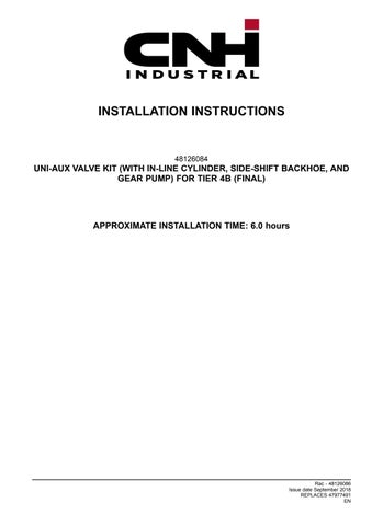
20. Connect hose (18) the rigid return - - tank tube (14) .
21. Connect the hose (10) the hammer valve “T” port straight fitting (6) .
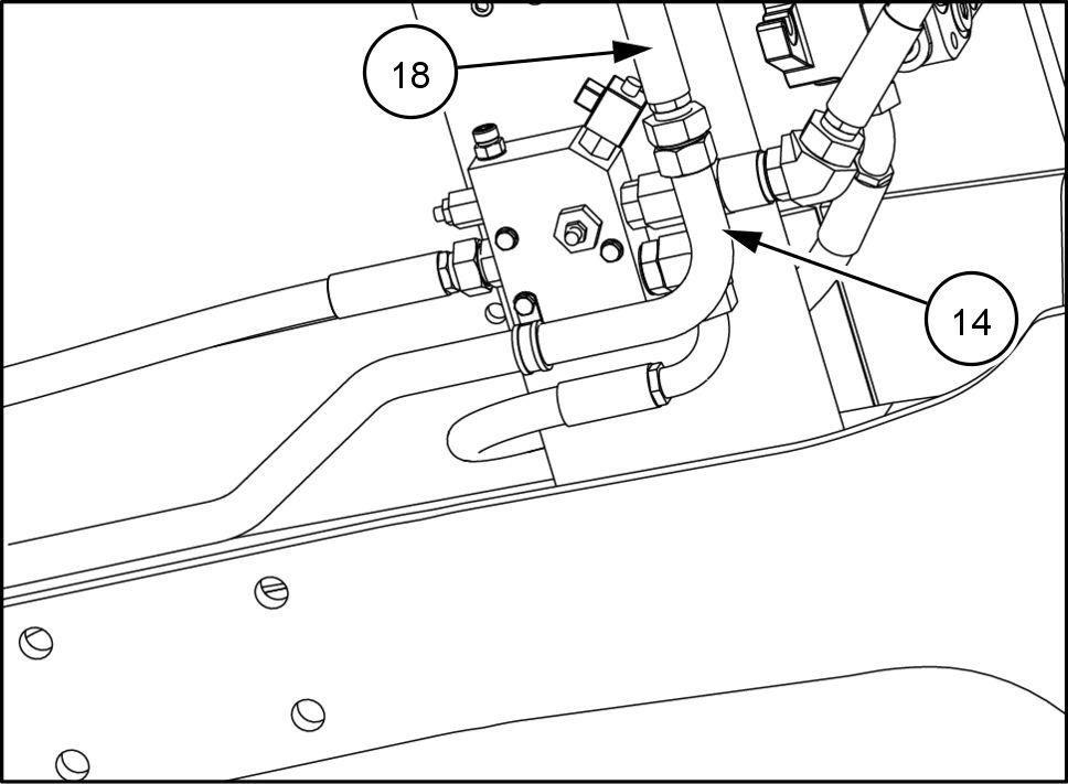
22. Connect the X- 810 connector the harness (20) the solenoid (S) the hammer control valve (1) .
RAIL17TLB0579BA 13

RAIL17TLB0580BA 14
RAIL17TLB0570BA 15
23. Route the return hose (18) and supply hose (17) the inside the backhoe swing support (F) . 24. Connect the supply hose (17) the “R” hole the right inner side the backhoe swing support (F) . 25. Connect the return hose (18) the “L” hole the right inner side the backhoe swing support (F) .
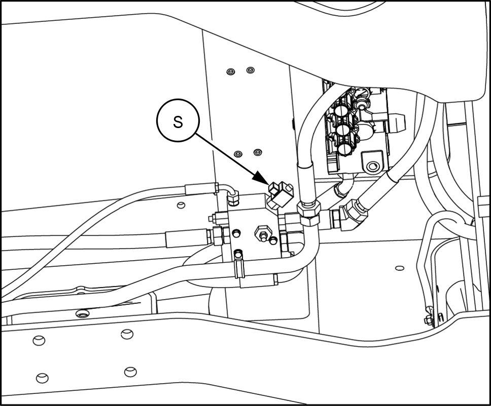
26. Install the 240 bar anti - shock pressure relief valve (17) into port “A” the bucket valve section the backhoe control valve. 27. Enter the cab. Remove the plug (J) then lift and remove the cab floor mat (Y) . needed, you may also remove the side panel (L) .
28. Insert the electric cable (20) in the lower part the side panel (L) and let it come out [side connector (20b) ] from the hole (M) . Fasten the plate (21) the connector (21b) . Then install the plate (21) the side panel (L) means the screws (2) . Connect the connector (20a) the electric cable (20) the harness the cab letting it pass through the lead the floor .

RAIL16TLB0426BA 16
RAIL16TLB0401BA 17

RAIL16TLB0398AA 18