1 minute read
Dia-3 Tester


The signals from the switches consist of either an open or closed circuit. The signal from the engine speed sensor consists of pulses ranging from 0 to 9.9 kHz (cycles per second), increasing as engine speed increases. The signals from the other sensors consists of 0 to 5-volt levels that vary according to the position of the associated control. The outputs consists of electrical power to the engine actuator and to the EDC. Zero to 12 volts are supplied to the engine actuator and 0 to 100 mA are supplied to the EDC. As the truck operates, the computer monitors the positions of the various manual controls in order to sense the desired performance; while at the same time, the computer monitors engine speed and engine actuator position in order to sense the actual performance. To make the actual performance match the desired performance, the computer varies the engine throttle position via the engine actuator and the drive pump output via the EDC.
The system can be diagnosed and adjusted with a diagnostic conti·ol, usually the SUSMIC-DIA 3 tester, that connects to the SUSMIC DIA 12 computer. Hydrostatic Drive Microprocessor
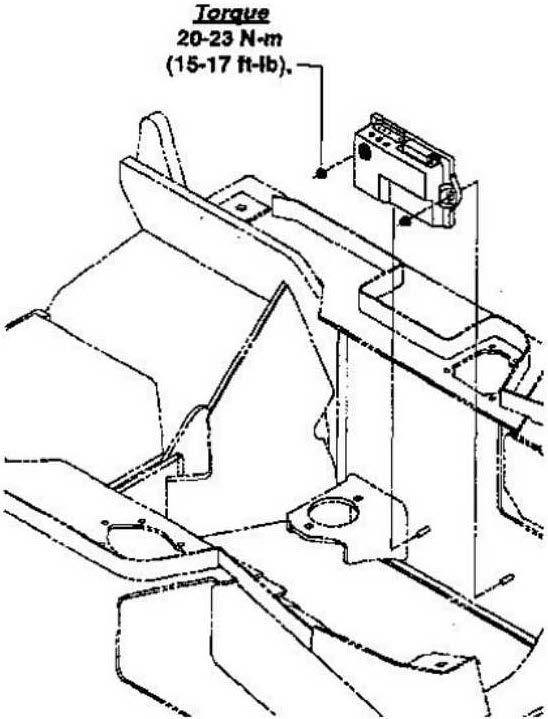
The hydrostatic drive system in the Clark CGC 20/25/30H, the CGP 20/25/30H, and the CDP 20/25/30H is controlled by a microprocessor. The microprocessor is mounted on the left side frame rail in the engine compartment. The microprocessor has a program loaded in it which analyzes the data inputted from the sensors and switches located on the truck. From this data, the engine speed and the displacement of the pump are controlled to provide drive capabilities and higher engine speeds for the mast functions. Computer