1 minute read
Sensors, Switches, and Actuators


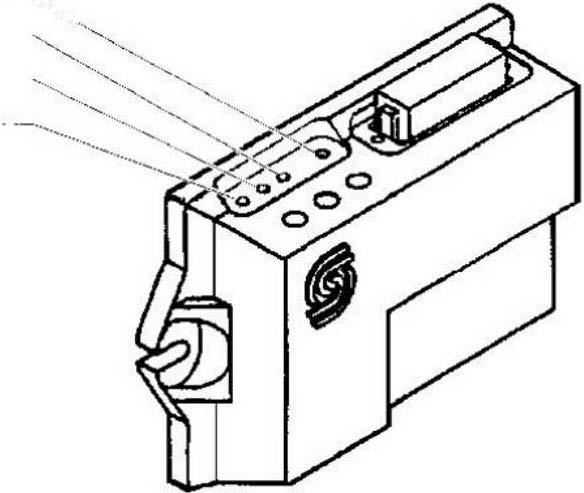
The memory of the microprocessor cannot be damaged by using the DIA-3 service tester or by disconnection of the battery. The internal components can be damaged or the memory can be affected by electric arcs so disconnection of the microprocessor from the wire harness prior to welding is required. LED Indicators Located on top of the microprocessor are four light emitting diodes (LED's), two green, one yellow, and one red. Looking down on the microprocessor in the truck, the rear most LED is green and indicates the 12 volt power from the trucks electrical system. If this LED is dim or not illuminated when the ignition switch is on, then a connection or low voltage problem exists. The next LED is also green and it indicates the microprocessor's internal 5 volt power supply. If this LED is dim or not illuminated when the ignition switch is on and the first LED is illuminated, than an internal problem with the microprocessor exists. This condition is not serviceable at the dealership. The LED third from the rear is yellow and indicates when the program is running. It flashes slow, (approximately once per second), when the program is running and fast if the program is not running. The forward most LED is red and indicates when an error condition exists. When the truck is in an en-or mode, the truck is programmed to not allow driving until the error is corrected.
The DIA-3 diagnostic instrument must be used to diagnose and con-ect the en-or.
Red Error Indication Yellow-Application Status· , , __
Green-5 Volt Power Supply Green-12 Volt Power Supply