1 minute read
Assembling cutter bars.....................................................4


20

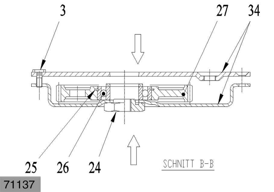
21 Assembling cutter bars Place a continuous silicone cord underneath the bolt heads (3). Press in rotor mounting bolts(3) in the cutter bar cover(34) (except for bolts near edge). Wipe off excess silicone. Place a continuous silicone strip in the slot of the nuts(24). Place nuts(24) at one level and place the cutter bar trough (34) on the nuts; align the nuts so they are centred on the matching drilled holes. Position intermediate gear wheels(27) in the trough while ensuring that the identification slot are up and the intermediate gear wheels are centred to the matching drilled holes. (Fig.20)
Position spacers (30) on the intermediate gear wheels. Apply a continuous, unbroken silicone strip to the outside edge of the trough.
Important!
Apply the silicone strip carefully, because this gasket must be absolutely leak-free!
Position cutter bar cover on the trough and fix with the expansion pins(1). Apply a continuous silicone strip on the two conical parts of the pin(29) (seal on cover and trough). Install pins(29) in sequence; this centres the spacers(30) and the gears(27). Fix bolts(28) with LOCTITE270. Tighten bolts (28) with a torque of 618÷638Nm while holding the nuts stationary. Check that the intermediate gear wheels run without problems. Turn over cutter bar. (Fig.21)