4 minute read
Reinforcement kit knoter frame


Marking of warning and danger notes
In this instruction manual all notes on the safety of persons and machine are highlighted with the following symbols. Pass all safety information on to other users.
Danger!
The non-observance of these notes will cause danger to the health and life of the operator or any other persons present. ☞Compliance with the described measures helps to avoid such dangers.
Attention!
The non-compliance with these notes may cause damage to the machine. ☞Compliance with the described measures helps to avoid risks for the machine.
1.Besides the information in this manual you should also observe the general safety regulations and the instructions for the avoidance of accidents. 2.Always wear light fitting clothes when working with the baler. Avoid baggy clothes! 3.Prevent fire hazards by keeping the machine clean!
Leaving the machine
1.When leaving the machine secure it against rolling away (wheel chocks). 2.Shut down the tractor engine, remove the ignition key and lock the cabin. 3.Do not leave the machine unattended as long as the tractor engine is running!
Note!
These notes enable a more effective and economical use of the machine.
Note!
Notes to be observed during disassembly / assembly.
Environment!
Non-compliance with these notes will cause hazards for the environment. The improper handling and/or disposal of hazardous substances (e.g. old oil) causes damage to the environment.
The warning signs on the machine contain information of importance for safe use of the baler. Compliance serves your safety!
For further safety regulations refer to the operating instructions for the machine.
Introduction
These instructions describe the work steps required to retrofit your Quadrant 2200. CLAAS Service Department
Scope of parts (841 788.0)
Pos. No. Spare
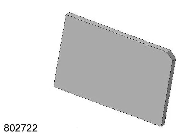
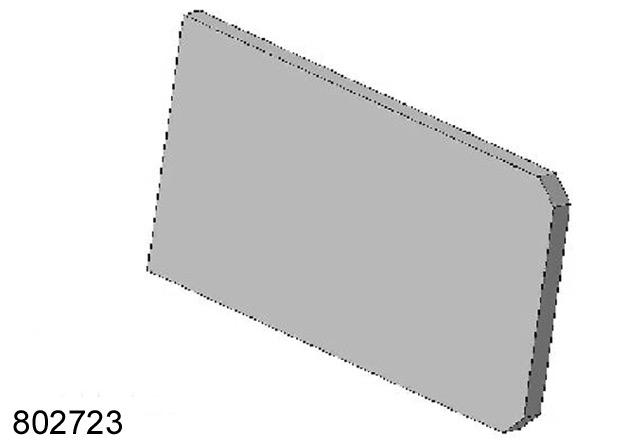
part Designation Qty. 1 841 783.0 Steel plate 6 2 841 785.0 Steel plate 1 3 841 786.0 Steel plate 1

1 2
1 3
2

L M N Before welding
Remove the paint from the welding areas (A to H). Clean the welding areas.
Before welding the steel plate
Fill the empty space between the machine sheet (L) and the steel plate (N) with welding (M). Flatten out the surface made of the steel plate (N) and the welding (M): the new steel plate will be weld on the flattened surface. Weld quality: EN 2883 EN 25817/B

2 Attention!
The weld must be operated by welding technicians.
(Fig.1,2)
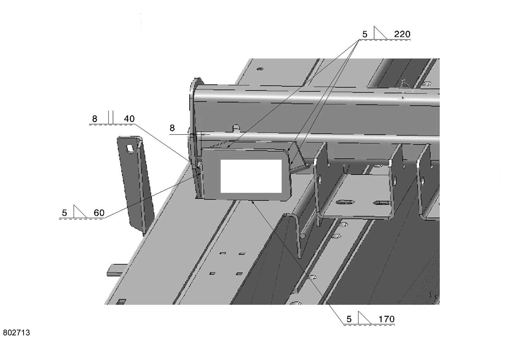
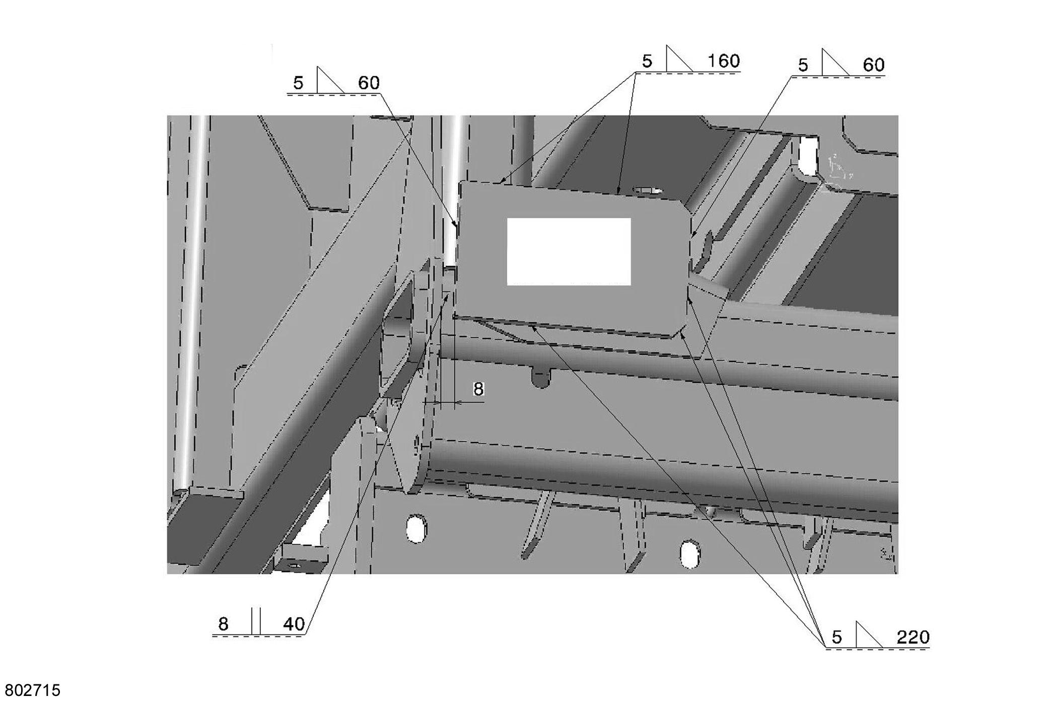
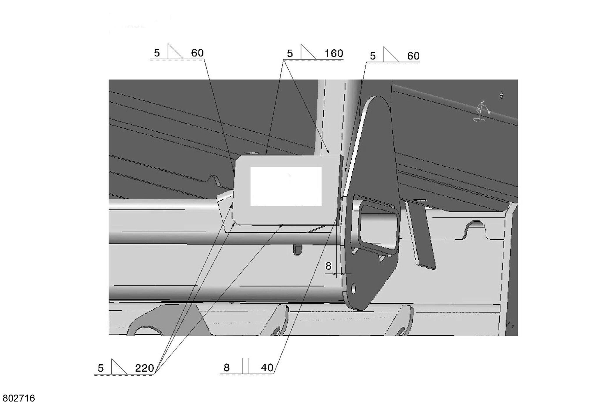
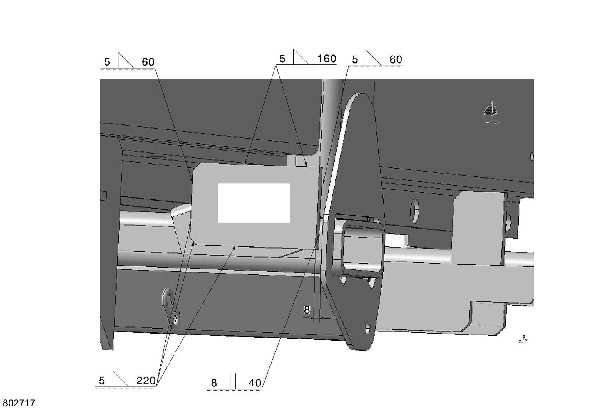
Steel plate welding
Weld the steel plate on the areas (A to H) as shown on the following plans. After welding, clean and paint the welded areas. (Fig.3-10)
1

1
4
1
1
6
1
1

8
2M 2


3
10
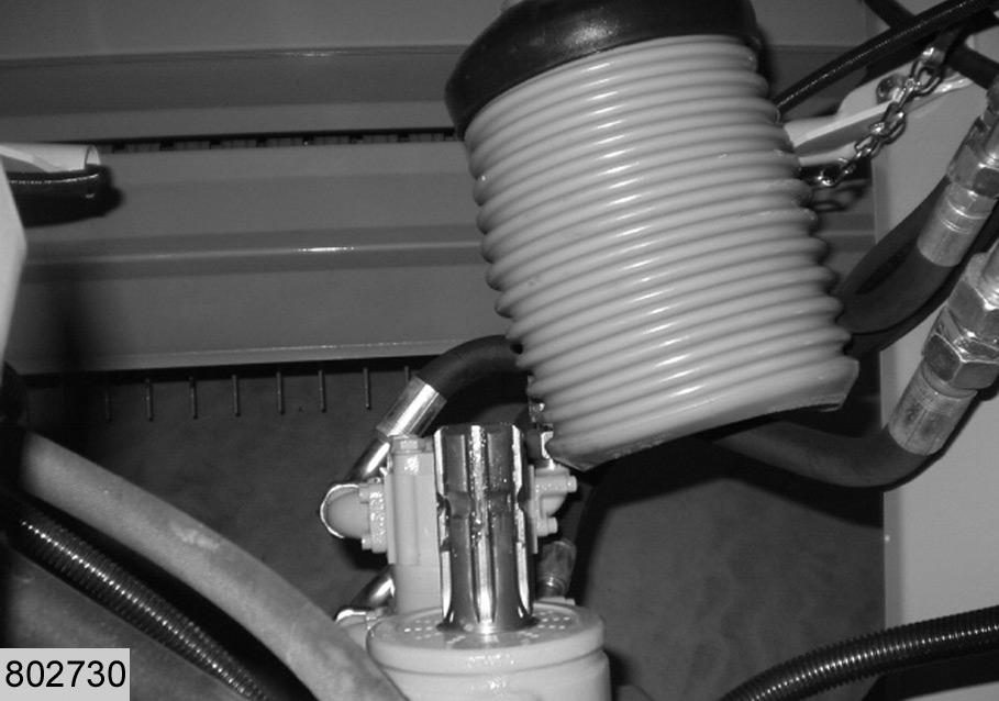
A B Adjusting the overload protection valve
Connect the machine to the tractor using the PTO shaft. Connect a manometer 600 bar to the measure port (A). (Fig.1)
C 1

Disengage the intermediate drive shaft (C). (Fig.2)
C 2

3
D
D I

E
4
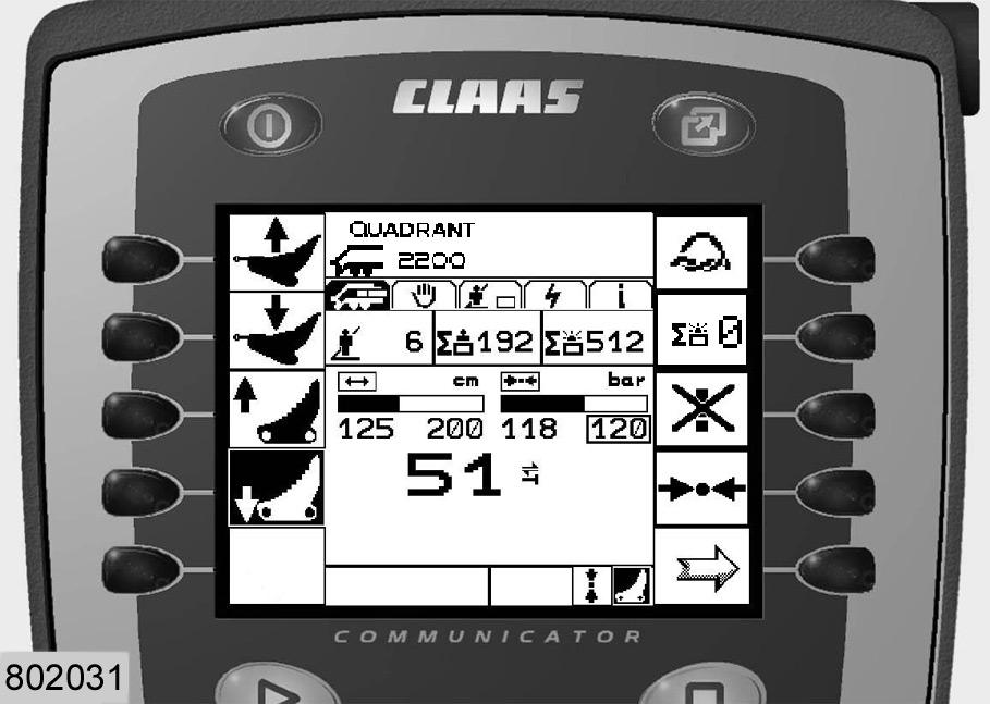
Switch on the Claas Communicator. Set the baling pressure (D) according to the operator’s manual.
Turn the incremental encoder (I) until the set point (D) appears surrounded by a frame.
Press the push button in the incremental encoder, the frame appears enlarged. Keep turning the incremental encoder, until the desired baling pressure (210 bar) is displayed. Press the push button to confirm the set baling pressure (it is thereby stored). Activate the PTO shaft (set to 1000 rpm), up to a baling pressure (D) of 210 bar.
210
210
Note!
The oil temperature must not exceed 60°.
5
J
H E
F F

G
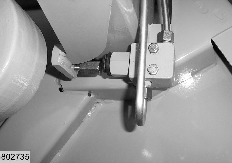
Fit a 3.2 mm wedge (J) between bolt (E) and valve (F). (Fig.6)
Tighten lock nut (H) (in direction of valve (F)) until pressure (G) is reduced to 30 ±5 bar. Tighten lock nut (H) only. (Abb.6,7)
Fit the machine to its original stand (without unsetting the pressure): connect the intermediate drive shaft , disconnect the manometer. Check the functions of the machine.