37 minute read
Return flow filter Sieve filter

from CLAAS Combines JAGUAR 900 - 830 900 - 830 PROFISTAR 900 - 830 Hydraulic Technical Systems Manual

5.1.3 Function of ground drive
Linde HPV - HMV ground drive, variable, with maximum propulsive force control
Motor started, ground speed control lever in neutral position - The ground drive feed pump (209) takes in cooled oil and pumps it to the pressure filter (102). - In case of cold oil, the ground drive feed circuit cold weather starting valve (718) prevents pressure build-up > 28 bar. - Oil flows through pressure filter (102). When the filter resistance exceeds a ∆p = 2 bar, the ground drive filter bypass valve (710) is opened and lets the oil continue to flow without filtering. - The ground drive feed pressure relief valve (716) controls the cooled and filtered oil to a pressure of 22.5 bar which is available as feed pressure at the following points: • Via orifice plate (401) ÿ 1.8 mm to the low-pressure hydraulics • to feed the ground drive multi-function valves (713) (714). • on both sides of the ground drive pump servo control (313) • at the ground drive control pressure speed control valve (616).
The oil pressure controlled to 21 bar by the low-pressure hydraulics pressure relief valve (729) is applied as control pressure to the ground drive motor servo control cylinder (355) via the ground drive servo control motor speed valve (737). The motor swivels to maximum input volume (= low speed and high propulsive force). The ground drive servo control direction pump valve (738) is springcentred and in its neutral position. Both cylinder spaces are connected with the tank via the ground drive control pressure direction valve (615).
Motor started, ground speed control lever moved to forward travel Pump: When moving the ground speed control lever, the ground drive control pressure direction valve (615) and the ground drive control pressure speed control valve (616) are actuated. This pre-selects the forward direction of travel and a control pressure proportional to the lever movement is built up for the servo control. At a control pressure of 4 bar and higher, the spring force at the ground drive servo control direction pump valve (738) is overcome. The ground drive servo control direction pump valve (738) now actuates the ground drive pump servo control cylinder (313). The HPV pump swivels proportionally to the position of the ground speed control lever. At a control pressure of 9 bar, the pump has reached its maximum position = max. volumetric displacement.
Motor: The control pressure generated by actuating the ground speed control lever is also applied at the servo control motor speed valve (737). When the ground speed control lever is moved so far that a control pressure of > 9 bar is built up, the spring force of this valve is overcome and the ground drive motor servo control cylinder (355) is adjusted proportionally to the position of the ground speed control lever towards low input volume = max. ground speed. Maximum ground speed is reached: • with motor HMV 105 at 10.5 bar and • with motor HMV 135 at 12 bar control pressure. The Bowden cable on the pump is mounted in the inner bore of the adjusting lever on ground drives with HMV 135 and in the outer bore with the HMV 105. The pivot position of the Bowden cable must not be modified.
Forward travel. Feed of cooled and filtered oil into the closed highpressure circuit. When driving, a pressure is generated in the high-pressure forward line which corresponds to the resistance to vehicular motion. A lower pressure (feed pressure) is available in the high-pressure backward line. This pressure difference actuates the ground drive oil tapping shuttle valve (721). Oil is tapped from the high-pressure backward line via the ground drive tap pressure control valve (719). Since the feed pressure is applied to the ground drive multi-function valves (713) and (714), fresh oil is introduced via the ground drive backward multi-function valve (713). The forward multi-function valve is closed by the oil pressure (due to the resistance to vehicular motion).
Backward travel. Feed of cooled and filtered oil into the closed highpressure circuit. When driving, a pressure is generated in the high-pressure backward line which corresponds to the resistance to vehicular motion. A lower pressure (feed pressure) is available in the high-pressure forward line. This pressure difference actuates the ground drive oil tapping shuttle valve (721). Oil is tapped from the high-pressure forward line via the ground drive tap pressure control valve. Since the feed pressure is applied to the ground drive multi-function valves (713) and (714), fresh oil is introduced via the ground drive forward multi-function valve (714). The backward multi-function valve is closed by the oil pressure (due to the resistance to vehicular motion).
Motor started, ground speed control lever moved to backward travel. Basically, the "Driving backward" control is the same as for "Driving forward". The difference is that the control pressure direction valve (615) is actuated in the backward position. The motor servo control is actuated via the ground drive control pressure shuttle valve (739) only on machines up to serial no. Ö.. Machines from serial no. Ö. actuate only the pump when in backward motion. The motor therefore remains in the large input volume range = large propulsive power. The shuttle valve has been dropped, see circuit diagram.
Maximum propulsive force control. The forward oil pressure of the high-pressure circuit is applied to the ground drive pressure cut-off valves (708). When increased resistance to vehicular motion occurs, high pressure of up to 400 bar may build up. This increased oil pressure opens the ground drive pressure cut-off valve (708). This open valve lets the control pressure of the motor and pump servo control relieve to the tank via the non-return valve (732) set to 4.6 bar. The ground drive motor servo control valve (355) is set back to its initial position due to the decrease of the control pressure to below 9 bar. The motor now swivels to its maximum input volume = increased propulsive force. By swivelling to the maximum input volume the forward oil pressure of the high-pressure circuit drops again. The forward ground drive pressure cut-off valve (708) closes again. The machine now moves at slow speed and maximum propulsive force.
Maximum pressure control: The forward or backward oil pressure of the high-pressure circuit is applied to the ground drive pressure cut-off valves 708 and the ground drive multi-function valves 713 or 714. When increased resistance to vehicular motion occurs, high pressure of up to 420 bar may build up. This increased oil pressure opens the corresponding ground drive pressure cut-off valve 708. This open valve lets the control pressure of the motor and pump servo control relieve to the tank via the non-return valve 732 set to 4.6 bar. The motor swivels to maximum input volume. However, when the pressure in the high-pressure circuit remains at more than 420 bar, the pump swivels back to minimum volumetric displacement (minimum speed) at 4.6 bar control pressure. As the pump does not swivel fully to the neutral position, a small oil flow is displaced via the ground drive forward or backward multi-function valves 713, 714. This reduces the thermal load when driving in the maximum pressure range.
Oil cooling The oil tapped into the motor body via the ground drive tap pressure control valve 719 is fed to the oil tank and the Venturi meter 442 via a connecting line. Along with the circulation oil flow of the steering system, a part of this heated oil is fed into oil cooler 109.
5.1.4 Testing and measurements
Measuring points
Measuring point (902): Ground drive high-pressure backward Measuring point (903): Ground drive high-pressure forward
Measuring point (908): Control pressure backward

Measuring port Tee union, Claas spare part no. 239039.0 Elbow union, Claas spare part no. 238693.0 Minimess port, Claas spare part no. 683656.0
Measuring adapter Minimess port M 14 x 1.5 = 238 711.0 with 683 656.1
Measuring preconditions Pressure measurements are carried out at minimum motor speed and at an oil temperature of 45 ñ 50 C.
Pressure fed into the high-pressure circuit
High pressure measurement • Ground speed control lever and transmission in neutral position. Set value: 20 + 4 bar at the measuring points (903) and (902).
• Move ground speed control lever fully and transmission in neutral position. Set value difference: 0 ... 1 bar at the measuring points (902) and (903).
• Engage transmission gear, • engage parking and service brake. • Move ground speed control lever slowly forward or backward to half the end position for a maximum of 5 seconds.
Set value: 420 ... 460 bar max. at the measuring points (902) and (903).
During this measurement, the value on the corresponding low-pressure side measuring point (903) or (902) must not fall below 14 bar.
Forward control pressure measurement • Install measuring port (908). • Switch transmission in neutral position. • Block the machine by actuating the service braking system and the parking brake. • Move the ground speed control lever fully to the front.
Set value: 11.5 bar for ground drive with HMV 105. Set value: 12.5 bar for ground drive with HMV 135.
5.1.5 Venting the HPV pump / HMV motor control pressure circuit.

Venting valve (104)
• Switch off engine, remove ignition key. • Switch transmission in neutral position. • Open venting valve 104 for approx. 2 turns. • Start motor and let it run at minimum rpm. • Block the machine by actuating the service braking system and the parking brake. • Move ground speed control lever fully to the front for approx. 30 seconds. • Switch off engine, remove ignition key. • Close venting valve 104 and lock it with the sealing flange nut.
Further filling and venting instructions For further filling and venting instructions please refer to the Repair Manual JAGUAR 492.
5.2
JAGUAR 20/25 km/h
5.2.1
Ground drive hydraulics circuit diagram
5.2 JAGUAR 20/25 km/h from serial no. 492 00133 up to serial no. 492 01613 5.2.1 Ground drive hydraulics circuit diagram

Item Designation Remark Z19 Hydraulic oil level switch (min.) Oil level OK, switch open Z20 Hydraulic oil temperature switch Normally open contact 102 Pressure filter 10 µm 104 Control pressure vent plug 107 Oil drain 109 Hydraulic system oil cooler 110 Oil tank 205 Working hydraulics pump 19 cm /rev. at n = 2890 rpm 209 Ground drive feed pump 22.5 cm /rev. at n = 2890 rpm 210 Ground drive variable displacement motor 105 / 85 cm /rev. for 830, 850 135 / 85 cm /rev. for 870, 890, 900 211 Ground drive variable displacement pump 105 cm /rev. 218 Steering hydraulics pump 8 cm /rev. at n = 2890 rpm 233 Silage additive pump 313 Ground drive pump servo control hydraulic cylinder 355 Ground drive motor servo control hydraulic cylinder 411 Orifice plate ∅ 1.8 mm 442 Venturi meter 609 Orbitrol steering unit rotary disc valve OSPC 250, mechanically actuated 615 Ground drive control pressure direction valve mechanically actuated 616 Ground drive control pressure speed valve mechanically actuated 708 Ground drive pressure cut-off valve hydraulically actuated 710 Ground drive filter bypass valve ∆p = 2 bar, hydraulically actuated 713 Ground drive multifunction valve backward valve 420 bar, hydraulically actuated 714 Ground drive multifunction valve forward valve 420 bar, hydraulically actuated 716 Ground drive feed pressure relief valve hydraulically actuated 718 Ground drive feed circuit cold weather starting valve hydraulically actuated 719 Ground drive tap pressure control valve hydraulically actuated 721 Ground drive oil tapping shuttle valve hydraulically actuated 725 Steering double shock valve hydraulically actuated 726 Steering pressure relief valve hydraulically actuated 728 Anti-cavitation valve (non-return valve) hydraulically actuated 729 Low-pressure hydraulics pressure relief valve 21+1 bar 732 Non-return valve hydraulically actuated 737 Ground drive servo control motor speed valve hydraulically actuated 738 Ground drive servo control forward/backward valve hydraulically actuated 742 Steering safety valve hydraulically actuated 902 Ground drive hydraulics high pressure backward measuring point 903 Ground drive hydraulics high pressure forward measuring point 908 Ground drive hydraulics control pressure forward measuring point 909 Steering hydraulics measuring point 910 Low-pressure hydraulics measuring point Minimess port
5.3
JAGUAR 20/25 km/h
5.3.1
Ground drive hydraulics circuit diagram
5.3 JAGUAR 20/25 km/h from serial no. 4920 0011 up to serial no. 4920 0132 5.3.1 Ground drive hydraulics circuit diagram

Item Designation Remark Z19 Hydraulic oil level switch (min.) Oil level OK, switch open Z20 Hydraulic oil temperature switch Normally open contact 102 Pressure filter 10 µm 104 Control pressure vent plug 107 Oil drain 109 Hydraulic system oil cooler 110 Oil tank 205 Working hydraulics pump 19 cm /rev. at n = 2890 rpm 209 Ground drive feed pump 22.5 cm /rev. at n = 2890 rpm 210 Ground drive variable displacement motor 211 Ground drive variable displacement pump See ESIS 218 Steering hydraulics pump 8 cm /rev. at n = 2890 rpm 233 Silage additive pump 313 Ground drive pump servo control hydraulic cylinder 355 Ground drive motor servo control hydraulic cylinder 411 Orifice plate ∅ 1.8 mm 442 Venturi meter 609 Orbitrol steering unit rotary disc valve OSPC 250, mechanically actuated 615 Ground drive control pressure direction valve mechanically actuated 616 Ground drive control pressure speed valve mechanically actuated 708 Ground drive pressure cut-off valve hydraulically actuated 710 Ground drive filter bypass valve ∆p = 2 bar, hydraulically actuated 713 Ground drive multifunction valve backward valve 420 bar, hydraulically actuated 714 Ground drive multifunction valve forward valve 420 bar, hydraulically actuated 716 Ground drive feed pressure relief valve hydraulically actuated 718 Ground drive feed circuit cold weather starting valve hydraulically actuated 719 Ground drive tap pressure control valve hydraulically actuated 721 Ground drive oil tapping shuttle valve hydraulically actuated 725 Steering double shock valve hydraulically actuated 726 Steering pressure relief valve hydraulically actuated 728 Anti-cavitation valve (non-return valve) hydraulically actuated 729 Low-pressure hydraulics pressure relief valve 21+1 bar 732 Non-return valve hydraulically actuated 737 Ground drive servo control motor speed valve hydraulically actuated 738 Ground drive servo control forward/backward valve hydraulically actuated 739 Ground drive control pressure shuttle valve 742 Steering safety valve hydraulically actuated 902 Ground drive hydraulics high pressure backward measuring point 903 Ground drive hydraulics high pressure forward measuring point 908 Ground drive hydraulics control pressure forward measuring point 909 Steering hydraulics measuring point 910 Low-pressure hydraulics measuring point Minimess port
5.4
JAGUAR SPEEDSTAR/PROFISTAR
- with electro-hydraulic actuation (EFA)
5.4.1
Ground drive hydraulics circuit diagram
5.4 JAGUAR SPEEDSTAR/PROFISTAR with electro-hydraulic actuation (EFA) 5.4.1 Ground drive hydraulics circuit diagram

Item Designation Y141 Ground drive forward solenoid coil
Y142 Ground drive backward solenoid coil
Y143 Ground drive/cut off valve solenoid coil Remark The solenoid coil is actuated by the ground drive module (A49) in a modulated way. Solenoid coil actuated = modulated control pressure = forward. The magnetic force is opposed to the control pressure. The solenoid coil is actuated by the ground drive module (A49) in a modulated way. Solenoid coil actuated = pressure at port (S) = backward The solenoid coil is actuated by the ground drive module (A49). It is permanently energized when the ignition (+15) is ON = the non-return valve is closed. In case of a panic braking (brake force > 55 kg) Y143 is not energized = the control pressure for servo control is connected to the tank via the open non-return valve = the ground drive variable displacement pump (211) moves to zero displacement.
Y144 Ground drive variable displacement motor solenoid coil
The solenoid coil is actuated by the ground drive module (A49) in a modulated way and changes the swivel angle of the ground drive variable displacement motor (110). Z19 Hydraulic oil level switch (min.) Oil level OK = switch open Z20 Hydraulic oil temperature switchNormally open contact Z46 Low-pressure hydraulics switch / ground drive oil pressure Monitors the pressure in the low-pressure hydraulics. Switch open = oil pressure OK Switch closed = oil pressure < 12 bar. B97 Drive hydraulics forward highpressure sensor Permanently transmits the ground drive forward pressure to the ground drive module (A49). This signal controls the motor rpm and the swivel angle of the ground drive variable displacement motor (210).
B98 Drive hydraulics backward highpressure sensor
Permanently transmits the ground drive backward pressure to the ground drive module (A49). This signal controls the motor rpm and the swivel angle of the ground drive variable displacement motor (210). 102 Pressure filter 10 µm 107 Oil drain 109 Hydraulic system oil cooler 110 Oil tank 112 Return flow filter 205 Working hydraulics pump 19 cm /rev. = 2890 rpm 209 Ground drive feed pump 22.5 cm /rev. at n = 2890 rpm 210 Ground drive variable displacement motor 211 Ground drive variable displacement pump See ESIS 218 Steering hydraulics pump Volumetric displacement: 11 cm /rev. Supplies volume flow for the steering system. 233 Silage additive pump (option) Is driven by the transfer gearbox. The circuit diagram shows the installation situation when the silage additive pump function is not needed. For information on the use of the silage additive pump, please refer to the corresponding fitting instructions.
313 Ground drive pump servo control hydraulic cylinder Controls the swivel angle of the ground drive variable displacement pump (211).
355 Ground drive motor servo control hydraulic cylinder
Controls the swivel angle of the ground drive variable displacement motor (210). 413 Orifice plate ∅ 2.2 mm, the low-pressure hydraulics and the suction drive motor are supplied via this orifice plate. 442 Venturi meter Feeds a partial volume flow from the steering hydraulics circuit into the cooling circuit.
609 Orbitrol steering unit rotary disc valve
Is mechanically actuated by the steering wheel
Item Designation
Remark 710 Ground drive filter bypass valve Opens at a filter resistance of ∆p = 2 bar 713 Ground drive multi-function valve backward - Pressure limitation: 420 bar - Feed for reloading into the closed circuit (replacing the leakage losses)
714 Ground drive multi-function valve forward
716 Ground drive feed pressure relief valve - Pressure limitation: 420 bar - Feed for reloading into the closed circuit (replacing the leakage losses) Opening pressure 24 bar. Determines the feed pressure.
718 Ground drive feed circuit cold weather starting valve 719 Ground drive tap pressure control valve Opens at a pressure of > 30 bar (when oil is cold).
Starts opening at p = 10 bar
721 Ground drive oil tapping shuttle valve
Is actuated by the respective high-pressure circuit.
738 Ground drive servo control restrictor valve In basic position, 2 compressed springs hold it exactly in centre position. Is controlled by the control pressure generated by the solenoid coils (Y141 or Y142). Actuates the 4/3 way valve mechanically.
757 Ground drive additional feed valve
Feeds additional volume flow into the feed and the low-pressure circuit when the pressure in port (Z) falls below 19 bar. 758 Ground drive restrictor valve Restricts the pressure drop in the ground drive pump servo control hydraulic cylinder (313) in case of a panic braking. 807 Line header P1 Volume flow input from pressure filter (102) P2 Output to the ground drive variable displacement motor (210), input (E). P3 Output to suction arm drive motor (228) P4 Output to low-pressure hydraulics
Mechanical zero position As long as the ground drive variable displacement pump (211) is not driven, it is in neutral position due to the mechanical zero position. The ground drive pump servo control hydraulic cylinder (313) is mechanically positioned in zero position by two pre-stressed compression springs, preventing the ground drive variable displacement pump (211) from providing volumetric displacement during the starting process. Pre-condition: the ground drive forward (Y141) and backward (Y142) solenoid coils are not energized. The setting of the mechanical zero position is carried out when installing the ground drive variable displacement pump (211) and cannot be modified from the outside.
Hydraulic zero position When the ground drive variable displacement pump (211) is driven, it is kept in neutral position by means of hydraulic zero position. Pre-condition: the ground drive forward (Y141) and backward (Y142) solenoid coils are not energized. The feed pressure (p7) acts on both sides in the ground drive pump servo control hydraulic cylinder (313) via the centre position of the ground drive forward/backward servo control valve (738) and the ground drive restrictor valve (758) and centres it in neutral position. At the same time, the ground drive restrictor valve (758) is switched from the restricted into the unrestricted position. The setting of the hydraulic zero position is carried out on the Linde test bench.
Control motion In the initial position, the solenoid coils (Y141, Y142) are not energized. Solenoid coil (Y143) is energized. The feed pressure (p7) is directed to the 2/2 way valves upstream of the restrictor. The servo control supply pressure (p8) downstream of the restrictor actuates the 2/2 way valves to through position. Due to this, feed pressure (p7) is applied to the non-actuated 4/2 way valves. At the same time, the ground drive restrictor valve (758) is switched from the restricted into the unrestricted position by the servo control supply pressure (p8). The ground drive variable displacement pump (211) is now in its hydraulic zero position.
Example E.g. when a current set by the electronic unit flows through the ground drive forward solenoid coil (Y141), a corresponding magnetic force is generated which actuates the 4/2 way solenoid valve proportionally. A pressure is directed to the ground drive forward servo control valve (738) as a function of this actuation. The valve moves by a corresponding path. The volume displaced from the opposite side flows into the tank via the 4/2 way solenoid valve (Y142). Due to the mechanical coupling, the actuation of the ground drive forward/backward servo control valve (738) results in a corresponding actuation of the 4/3 way valve. This actuates the ground drive pump servo control hydraulic cylinder (313) which swivels the ground drive variable displacement pump (211) to the corresponding angle. When the electronic signal at the ground drive forward solenoid coil (Y141) is decreased, the proportional 4/2 way valve reduces the pressure to the ground drive forward/backward servo control valve (738) and the swivel angle of the ground drive variable displacement pump (211) becomes smaller.
Ground drive/cut off valve solenoid coil (Y143) The Ground drive/cut off valve solenoid coil (Y143) is de-energized in case of a panic braking (pedal force > 600 N) (see also Technical Systems ñ Electric System). When the ground drive/cut off valve solenoid coil (Y143) is deenergized, the magnetic needle is retracted. The ball lifts off from its seat and relieves the servo control supply pressure (p8) towards the tank. This has the following result: The 2/2 way valves of the solenoid coils (Y141 and 142) are switched back to blocked position and therefore take away the supply pressure to the proportional 4/2 way valves. This makes the latter return to their initial position. Since the servo control supply pressure (p8) applied at the ground drive forward/backward servo control valve (738) collapses, the compressed springs move this valve to its neutral position. The 4/3 way valve is moved to its centre position due to the mechanical link. Switching off the ground drive/cut off valve solenoid coil (Y143) creates a pressure drop downstream of (p8) and switches the ground drive restrictor valve (738) from the unrestricted to the restricted position. The ensures smooth deceleration since the return time of the ground drive pump servo control hydraulic cylinder (313) is longer.
5.4.3 Components Ground drive variable displacement pump (211)

211 Ground drive variable displacement pump
5.4.3.2 Solenoid coil: Y141, Y142, Y143
The solenoid coil is actuated by the ground drive module (A49) in a modulated way. Solenoid coil actuated = modulated control pressure = forward. The magnetic force is opposed to the control pressure. Y141 Ground drive forward solenoid coil Solenoid coil actuated = modulated control pressure build-up = forward.
Y142 Ground drive backward solenoid coil Solenoid coil actuated = pressure at port (S) = backward
Y143 The solenoid coil is actuated by the ground drive module (A49). It is permanently energized when the ignition (+15) is ON = the non-return valve is closed. In case of a panic braking (brake force > 55 kg), Y143 is not energized (see also "Electric System chapter") = the control pressure for servo control is connected to the tank via the open non-return valve = the ground drive variable displacement pump (211) moves to zero displacement.
211 Ground drive variable displacement pump P, S Outputs to ground drive variable displacement motor (210)


5.4.3.3 Ground drive variable displacement motor (210)
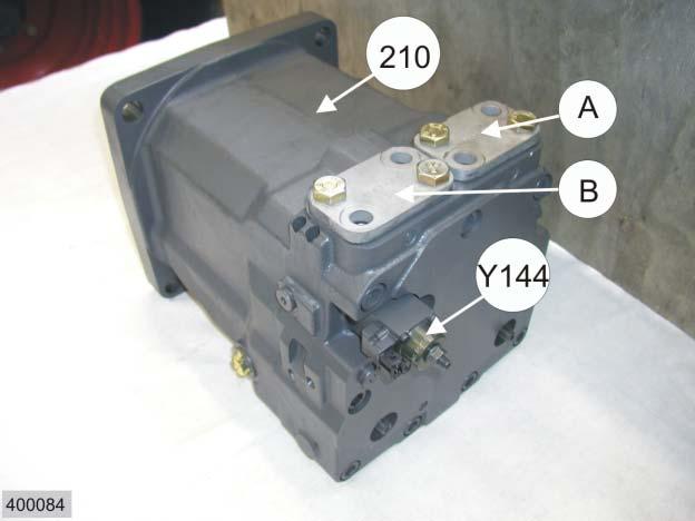
210 Ground drive variable displacement motor
Y144 The ground drive variable displacement motor solenoid coil is actuated by the ground drive module (A49) and changes the swivel angle of the ground drive variable displacement motor (210). A Port. Volume flow generates counterclockwise rotation. B Port. Volume flow generates clockwise rotation.
In its initial position, the ground drive variable displacement motor (210) is always set to maximum input volume and is adjusted continuously towards the minimum input volume. This control motion is electrohydraulical and proportional to the actuation current of Y144.

When the ground drive variable displacement motor solenoid coil (Y144) is not energized, the control pressure, via port (E), acts in the rod space of hydraulic cylinder (355) which positions the ground drive variable displacement motor (210) to maximum input volume. When the ground drive variable displacement motor solenoid coil (Y144) is energized, this current creates a proportional magnetic force which moves the spool and counteracts the spool spring. A control pressure is accordingly directed into the piston top space of hydraulic cylinder (355) which controls the swivel angle of the ground drive variable displacement motor (210) towards minimum input volume.
5.4.3.4 Ground drive additional feed valve (757)

205 Working hydraulics pump: 19 cm , nmax = 2890 rpm 218 Steering hydraulics pump: 11 cm /rev. 757 Ground drive additional feed valve 916 Working hydraulics pump measuring point
P5 Working hydraulics port T Tank port Z Additional feed port into feed pressure circuit and low-pressure hydraulics.
Function

When the pressure at port (Z) falls below 19 bar, the ground drive additional feed valve (757) feeds an additional volume flow into the feed and the low-pressure circuits.
In the initial position (see circuit diagram), the following circuits are supplied:
• The high-pressure circuit (port P5) and • The feed pressure circuit and/or the low-pressure circuit (port Z).
When the pressure in port (Z) rises above 19 bar, the valve switches and supplies the working hydraulics exclusively via port (P5).
When the pressure in port (Z) falls below 19 bar, the valve switches to its initial position. Now a partial volume flow flows via port (Z) into the feed pressure circuit and into the low-pressure hydraulics. This condition is maintained until the pressure in port (Z) rises above 19 bar.
5.4.3.5 Ground drive filter bypass valve (710)

710 Ground drive filter bypass valve

Task B98 Drive hydraulics backward high-pressure sensor. The drive hydraulics forward high-pressure sensor (B97) is installed on the opposite side. 102 Pressure filter
The ground drive hydraulics forward (B97) and backward (B98) highpressure sensors are installed in the pressure outlets of the ground drive variable displacement pump (211).
The ground drive hydraulics forward high-pressure sensor B97 permanently transmits the ground drive pressure to the ground drive module (A49). This signal controls the motor rpm and the swivel angle of the ground drive variable displacement motor (210).
The ground drive hydraulics backward high-pressure sensor B98 permanently transmits the ground drive pressure to the ground drive module (A49). This signal controls the motor rpm and the swivel angle of the ground drive variable displacement motor (210).
5.4.3.7 Line header (807)

Item Designation Remark 102 Pressure filter 413 Orifice plate ∅ 2.2mm 807 Line header Z46 Pressure switch 12 bar NC contact. Monitors the pressure in the low-pressure hydraulics. P1 Volume flow input from pressure filter (102) P2 Output to the ground drive variable displacement motor (210), input (E). P3 Output to suction arm drive motor (228) P4 Output to low-pressure hydraulics


Oil cooling The oil tapped into the motor body via the ground drive tap pressure control valve (719) is fed to the oil tank and the Venturi meter 442 via a connecting line. Along with the circulation oil flow of the steering system, a part of the heated oil is fed into oil cooler 109.
a Input from Orbitrol steering unit rotary disc valve (609) port (T) b Output to oil cooler (109) c Output to the ground drive variable displacement motor (110), port (E).
5.4.4 Diagram: Propulsive power (F) / Ground speed (v)

Curve a The first forward gear is engaged, speed control lever is moved from its 0 position to the front.
Curve section 1: When starting, the ground drive variable displacement pump HPV swings from a volumetric displacement of 0 towards maximum displacement. The ground drive variable displacement motor HMV stands at its maximum input volume.
Now: - maximum propulsive power is reached; - the max. ground speed is approx. 7.5km/h.
Curve section 2: The ground drive variable displacement pump HPV stands at maximum displacement. The ground drive variable displacement motor HMV swivels from its maximum input volume to approx. 98cm /rev. of input volume.
Now: - the propulsive power decreases; - the ground speed increases up to approx. 16.5km/h.
Curve b The second forward gear is engaged, the ground speed control lever is moved from its 0 position to the front.
Curve section 3: When starting, the ground drive variable displacement pump HPV swings from a volumetric displacement of 0 towards maximum displacement. The ground drive variable displacement motor HMV stands at its maximum input volume.
Now: - the propulsive force is smaller than in the first gear - the max. ground speed is approx. 19 km/h.
Curve section 4: The ground drive variable displacement pump HPV stands at maximum displacement. The ground drive variable displacement motor HMV swivels from its maximum input volume to approx. 98cm /rev. of input volume.
Now: - the propulsive power decreases; - the ground speed increases up to approx. 40km/h.
5.4.5 Testing and measurements
Pressure testing with the high-pressure sensors B97 and B98, using the display of the CIS terminal
Note: Set cursor in CIS to the ground speed control lever symbol (see Operator's Manual).
Volt display: B97 Drive hydraulics forward high-pressure sensor
Volt display: B98 Drive hydraulics backward high-pressure sensor


Measuring values table of high-pressure sensors B97 and B98 Pressure Volt 0 bar 0.2 ñ 0.3 Volt 20 bar 0.4 Volt 30 bar 0.4 ñ 0.5 Volt 40 bar 0.5 ñ 0.6 Volt 100 bar 1.0 Volt 200 bar 1.7 ñ 1.8 Volt 300 bar 2.5 Volt 400 bar 3.2 ñ 3.3 Volt 420 bar 3.4 Volt 440 bar 3.5 Volt 450 bar 3.6 Volt 460 bar 3.7 Volt
Function testing of sensors:
Measuring preconditions for pressure tests:
Pressure fed into the high-pressure circuit
High pressure measurement
Note: With the motor shut off and vehicle brakes applied
• Switch on the ignition • Set cursor in CIS to the ground speed control lever symbol (see Operator's Manual).
The CIS displays 0.2 ñ 0.3 Volt on the measuring values displays (B97) and (B98) which corresponds to a sensor display of 0 bar. (see table).
Set cursor in CIS to the ground speed control lever symbol (see Operator's Manual). Pressure measurements are carried out at minimum motor speed and at an oil temperature of 45 ñ 50 C.
• Ground speed control lever and transmission in neutral position.
Set value: 20+4 bar on the measuring value displays B97 and B98 (see table).
• Engage second gear, • apply parking brake. • Move ground speed control lever slowly forward or backward to half the end position for a maximum of 5 seconds.
During this high-pressure measurement, the pump is in limiting mode (maximum pressure control). The Volt display in the CIS varies, the highest value being decisive for the measurement.
Set value: 420 ... 460 bar on the measuring value displays B97 and B98 (see table).
During this process, the value on the corresponding low-pressure side measuring value displays B97 or B98 must not fall below 20 bar (see table).
6 Float position
6.1 Working method...................................................................... 6-2
6.2 Operation ................................................................................ 6-3
6.3 Sensors................................................................................... 6-5
6.4 Function...................................................................................6-6
6.1 Working method

Pitching may occur during transport travel with heavy front attachments mounted. This applies particularly when travelling at high speeds on uneven roads.
This • considerably reduces the driving comfort, • reduces the driving safety and • causes high dynamic loads on mechanical components.
The pitching modifies the pressure in the front attachment hydraulic cylinders. These pressure changes are detected by a pressure sensor, transmitted into the CONTOUR module as a signal and evaluated there. The CONTOUR module actuates the solenoid valves for raising or lowering the front attachment as a function of these signals. Pitching is counteracted by slightly raising or lowering the front attachment.
• The float position offers the following benefits: • high driving comfort • safe vehicle handling • lower mechanical loads
6.2 Operation

6.2.1 Learning the centre pitching axis 1. Switch off the main drive switch (S25). 2. Set switch (S52) to road travel position. 3. Raise the front attachment to a height of approx. 400 mm. 4. Keep the CAC switch (S38) "Cutting height control/Automatic ground pressure control" pressed for approx. 5 seconds until a threefold warning tone is heard. The position of the centre pitching axis has now been learned. In this front attachment position, • Sensor (B2) "Ground pressure oil pressure" detects the pressure in the hydraulic cylinders "Raise/lower front attachment". • Sensor (B35) "Feed rake conveyor position" detects the front attachment position. Both signals are transmitted to the CONTOUR module (A11). The learned "centre pitching axis" is permanently saved in the CONTOUR module (A11). It will not be deleted by switching the ignition OFF and ON. The existing value can only be overwritten by another learning procedure.
6.2.2 Activating the float position

1. Switch off the main drive switch (S25). 2. Switch on road travel switch (S52). 3. Raise the front attachment to an arbitrary height. 4. Press CAC switch (S38) "Cutting height control/Automatic ground pressure control". The front attachment is now moved to the "centre pitching axis" position.

The activated float position is identified by the letters "A" (see arrows) in the display. The left-hand bar graph shows the ground pressure and the right-hand bar chart the position of the front attachment.
Pitching is deactivated by manually raising or lowering the front attachment.

B2 The "Ground pressure oil pressure" sensor is mounted at the front right-hand side on the feed rake conveyor. It detects the pressure in the "Raise/lower front attachment" hydraulic cylinders and transmits the signal to the CONTOUR module (A11).
B35 The "Feed rake conveyor position" sensor is mounted at the front right-hand side on the feed rake conveyor. It detects the front attachment position and transmits the signal to the CONTOUR module (A11).
Example: The following example explains the working method of the float position: After the centre pitching axis has been learned, the pressure in the "Raise/lower front attachment" hydraulic cylinders is 100 bar. This pressure is detected by sensor (B2) "Ground pressure oil pressure". A pressure tolerance range of +/- 20 bar is stored in the CONTOUR module (A11). The pressure peaks occurring during road travel (curve a) are outside of the pressure tolerance range.

The CONTOUR module actuates the solenoid valves for raising or lowering the front attachment correspondingly. Slightly raising or lowering the front attachment counteracts the pitching to such an extent that the pressure remains within the stored pressure tolerance range of +/- 20 bar (curve b).
When the pressure is within the stored pressure tolerance range of +/- 20 bar, but the front attachment moves away too much from the centre pitching axis during its compensating motions, it is returned by the position sensor.
7 Compressed-air system
7.1 Trailer brake system circuit diagram....................................... 7-2
7.2 Motor restrictor / compressed-air coupling............................. 7-6
7.1 Trailer brake system circuit diagram

Key to diagram: 1 Compressor ...................................................(350 ñ 380 cm3) 2 Pressure control valve ...................................(12.5 bar) 3a Air accumulator (20 litres) 3b Air accumulator (20 litres) 4 Frost protection pump 5 Dewatering valve (automatic) 6 Pressure gauge (10 bar) in the cab 7 Pressure relief valve (8 bar) 8 Trailer control valve (2-wire) 9 Accumulator service line hose coupler (red) 10 Brake service line hose coupler (yellow) 11 Safety valve (14 bar) 12 Relief valve (8.5 bar) 13 Relief valve (6 bar) 14 Compressed-air coupling 15 Solenoid valve (proportional) Y100-1 16 Pressure gauge (16 bar) 17 Solenoid valve (4/2-way) Y100-2 18 Shuttle valve
a Brake pressure input (service brake) b Engine brake port (depending on equipment fitted)
Description of function: 1/2
1 Compressor The compressor is permanently driven by the diesel engine and conveys compressed air into the system. Compressor start at p < 11.5 bar Compressor stop at p > 12.5 bar - for controlled compressors.
2 Pressure control valve -Controlled compressor:
The pressure control valve controls the compressor and consequently the operating pressure.
-Uncontrolled compressor:
The operating pressure is adjusted directly by the pressure control valve.
4 Frost protection pump Automatic injection of antifreezing agent into the brake system to protect it against freezing of tubes and downstream units.
5 Dewatering valve Automatic draining of condensate from the air accumulator.
6 Pressure gauge Displays the pressure in the accumulator circuit (target value = 8 bar).
7 Pressure relief valve Limits the pressure (output 2) in the accumulator circuit to 8 bar. This pressure is applied to the following components: - Pressure gauge 6 - Accumulator service line hose coupler (red) 9 - Trailer control valve 8, port 1 - Solenoid valve 15 (Y100-1), port 1 - Solenoid valve 17 (Y100-2), port 1
8 Trailer control valve The trailer control valve is actuated hydraulically by the liquid pressure in the service brake system (ports 41 and 42). Actuation starts at 8 bar of liquid pressure in the service brake system. Full actuation at 35 bar of liquid pressure in the service brake system.
Depending on the actuation, compressed air (output 2) is transported to solenoid valve (15), input 4, via the shuttle valve (18).
9 Accumulator service line hose coupler A pressure of 8 bar is constantly applied here.
10 Brake service line hose coupler Connection of brake line between tractor and trailer (8 bar max.)
11 Safety valve Safeguards the compressed air system at 14 bar.
Description of function: 1/2
12 Relief valve Safeguards the pressure in the air accumulator (3b) at 8.5 bar min.
13 Relief valve Safeguards the pressure in the air accumulator (3a) at 6 bar min.
14 Compressed-air coupling Port for external compressed-air consumers (cleaning, tyres, Ö)
15 Solenoid valve (Y100-1) Governs the building-up of pressure at the service line hose coupler (10) while braking. The following control modes apply: a) pneumatic = Control pressure from trailer brake valve (8) or from the solenoid valve (17=Y100-2) b) electrical = Signal upon pulling back (deceleration) of ground speed control lever.
16 Pressure gauge Displays the pressure in the air accumulator (target value = 12.5 bar).
17 Solenoid valve (Y100-2) For braking, this valve passes the applied pressure of 8 bar (port 1) on to solenoid valve (15, port 4).
No electrical triggering of solenoid valve (17): The passage from port 1 to port 2 is open when: - the ignition is OFF - and/or the parking brake is actuated.
Electrical triggering of solenoid valve (17): The passage from port 1 to port 2 is closed when: - the ignition is ON - and/or the parking brake is not actuated.
18 Shuttle valve Directs either the pressure from the trailer control valve (8, port 2) or the solenoid valve (17=Y100-2, port 2) to solenoid valve (15=Y100-1, port 4).
7.2 Motor restrictor / compressed-air coupling

Key to diagram: 1 Compressor (350 ñ 380 cm3) 2 Pressure control valve (12.5 bar) 3b Air accumulator (20 litres) 4 Frost protection pump 5 Dewatering valve (automatic) 11 Safety valve (14 bar) 12 Relief valve (8.5 bar) 14 Compressed-air coupling 16 Pressure gauge (16 bar)
b Engine brake port (depending on equipment fitted)
Description of function:
1 Compressor The compressor is permanently driven by the diesel engine and conveys compressed air into the system. Compressor start at p < 11.5 bar Compressor stop at p > 12.5 bar
2 Pressure control valve Controlled compressor:
The pressure control valve controls the compressor and consequently the operating pressure.
Uncontrolled compressor:
The operating pressure is adjusted directly by the pressure control valve.
4 Frost protection pump Automatic injection of antifreezing agent into the brake system to protect it against freezing of tubes and downstream units.
5 Dewatering valve The dewatering valve serves for automatically draining the condensate collected in the air accumulator.
11 Safety valve Safeguards the compressed-air brake system at 14 bar max.
12 Relief valve Safeguards the pressure in the air accumulator (3b) at 8.5 bar min.
14 Compressed-air coupling Port for external compressed-air consumers (cleaning, tyres, Ö)
16 Pressure gauge Displays the pressure in the air accumulator - target value 12.5 bar.
Index
Index: A Accumulator.....................................................3-12 Accumulator circuit...........................................3-31 Accumulator volume switching-over................3-30 Additional control unit ......................................3-16 Additional feed ................................................5-36 Autopilot...........................................................2-10
B Bypass valve....................................................5-37
C Circuit diagram.................................................5-4, 5-16, 5-20, 5-24
Compressed-air coupling.................................7-8
Compressed-air system .................................7-1
Corn Cracker ..................................................3-18
D Direct ñ Disc.....................................................3-30
E Emergency steering.........................................2-7
F Filling and venting instructions.........................5-14
Float position....................................................6-1
Flow control valve ...........................................3-11, 4-20
G Ground drive control........................................5-28
Ground drive hydraulics...................................5-1
Ground drive control........................................5-28
H High-pressure measurement...........................5-43
High-pressure sensors.....................................5-43
Hitch.................................................................3-14
HMV motor.......................................................5-7
HPV pump........................................................5-7
Hydraulic circuit diagram .................................1-4, 2-2, 3-4, 4-2
K Knife support.................................................... 4-26
L Line header...................................................... 4-24, 5-39 Load switch-over..............................................3-28
M Main valve........................................................3-8
Master valve .................................................... 3-8
Measured value table......................................5-43
Motor restrictor ...............................................7-8
P Pressure control...............................................5-10
Pressure limitation...........................................1-28, 3-17
Pressure relief valve ......................................3-9, 4-14
Propulsive power.............................................5-6, 5-41
Pulse width modulation ...................................3-10
R Raise/lower front attachment...........................3-8
Reverse front attachment ................................3-22
Reverser drive..................................................3-24
S Sharpening..............................................................3-16
Shifter rail locking....................................................4-18
Shut-off valve...........................................................5-29
Steering actuation....................................................2-6
Steering hydraulics..................................................2-1
Suction arm drive.....................................................4-22
T Trailer brake system................................................7-3
U Upper discharge chute ............................................3-26
V Valve combination...................................................3-10
Valve inserts ...........................................................1-22
Variable displacement motor...................................5-34
Venting..................................................................... 3-19, 4-19, 5-14
Venturi nozzle..........................................................5-40
W Working hydraulics..................................................3-1
Following the policy of the CLAAS KGaA mbH to improve their products as technical developments continue, CLAAS reserve the right to make alterations which must not necessarily correspond to text and illustrations contained in this publication, and without incurring obligation to alter any machines previously delivered.
Technical data, dimensions and weights are given as an indication only. Responsibility for errors or omissions not accepted.
Reproduction or translation of this publication, in whole or part, is not permitted without the written consent of the CLAAS KGaA mbH.
All rights under the provision of the Copyright Act reserved.
CLAAS KGaA mbH 33426 Harsewinkel Germany
Our contribution to the environment: CLAAS have printed this manual on 100 % chlorine free paper.
CLAAS KGaA mbH Postfach 1163 33426 Harsewinkel Tel. +49 (0)5247 12-0 www.claas.com
0298 712.3 SYS-H JAGUAR 900-830 EN - 03.05 - NF Printed in Germany