1 minute read
Tapered-roller bearing


Type : CL 19 Transfer case in CLAAS SFM Grassland machine Drawing no.: VGZ 75-521 Valid as of serial no. : 01 Preparation of data : 22.01.2007 Author: Rauh
4. Release the lock nut (size 24 or 30) and turn the adjusting screw with socket wrench size 8 or 10 manually clockwise until it lies flush with the inside of the piston. 5. Press back the thrust bolt using a suitable screwdriver until it has contact with the piston.
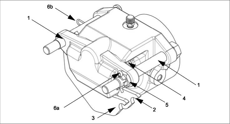
Drawing: Exchanging the lining pads
1 guide bolt 2 lining pad 3 lining pad 4 permanent magnet 5 castellated nut 6a safety splint 6b safety clip
6. Depending on the free space available, release one of the two guide bolts, removing the safety splint, unscrewing the castellated nut and pulling the guide bolt out of the brake anchor plate. Now, the brake lining pads can be removed tangentially to the brake disk.
Note:
In the event of minimal clearance, i.e. it is not possible for space reasons to exchange the brake lining plate in accordance with these instructions; the brake must be removed completely. To do this, pull both guide bolts out of the brake anchor plate.
Caution! Check the pressure hose. If the pressure hose is to short, it must be unscrewed to remove the brake. Before the pressure hose can be released the brake must be emergency released.
7. Exchange the brake pads and insert the guide bolts into the brake anchor plate. If you have removed the complete brake you have to amount the brake on both guide bolt again, now. 8. Check both permanent magnets if they still have sufficient magnetic force to hold the brake lining plates.