5 minute read
Chapter 1.3 Overall hydraulic system Quadrant 2100 N


1.3.2 Quadrant 2100 N overall hydraulic system circuit diagram - from serial no. 742 00 048 (for machines equipped with a turbofan)....................34
1.3.1 Overall hydraulic system circuit diagram
Quadrant 2100 N
up to serial no. 742 00 047
1.3.1 Quadrant 2100 N overall hydraulic system circuit diagram - up to serial no. 742 00 047
1.3.2 Overall hydraulic system circuit diagram
Quadrant 2100 N
from serial no. 742 00 048
(for machines equipped with a turbofan)
1.3.2 Quadrant 2100 N overall hydraulic system circuit diagram - from serial no. 742 00 048 (for machines equipped with a turbofan)
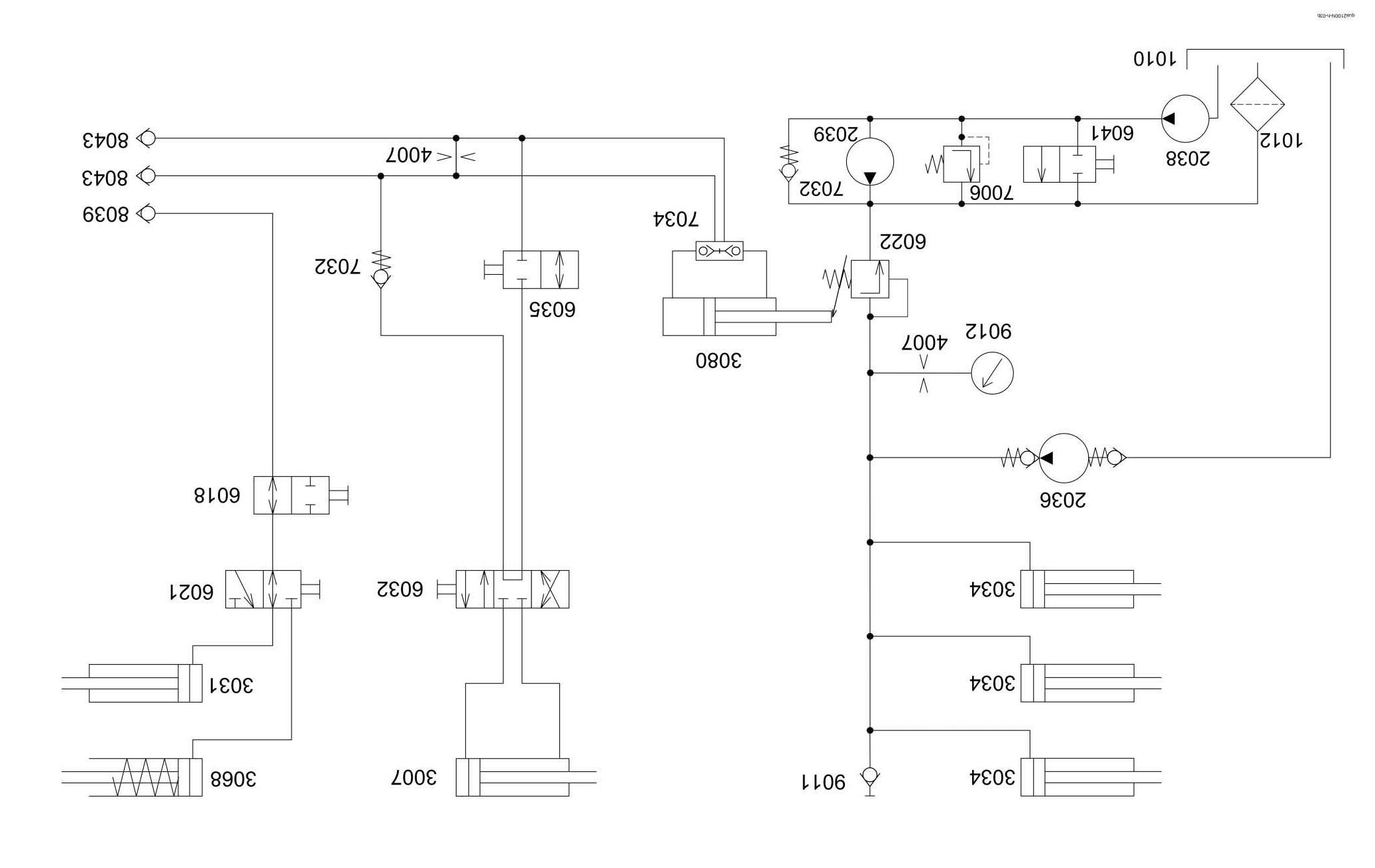
1.3.3 Key to diagram:
1010 Oil tank (baling pressure hydraulic system) 1012 Return filter 1021 Pressure filter (baling pressure hydraulics)
2036 Baling pressure hydraulic system pump (1.5 l/min) 2038 Knotter fan pump 2039 Knotter fan motor
3007 Bale ejector hydraulic cylinder 3031 Pick-up hydraulic cylinder 3034 Baling chamber hydraulic cylinder 3068 Stand hydraulic cylinder 3080 Baling pressure adjustment hydraulic cylinder
4007 Orifice plate (1.0 mm)
6018 Tractor shut-off valve 6021 Jack stand / pick-up reversing valve 6022 Baling pressure relief valve 6032 Bale ejector control valve 6035 Bale ejector shut-off valve 6041 Shut-off valve
7006 Pressure relief valve (80+ 5 bar) 7032 Non-return valve 7034 Lock-up valve unit 7117 Knotter fan pressure relief valve (100 bar)
8039 Quick release coupling (stand) 8043 Quick release coupling (baling pressure setting, ejecting bales)
9011 Baling pressure measuring point 9012 Baling pressure gauge
1.3.4 Description of function:
Connection to tractor hydraulic system
The attachment can be connected to any tractor available on the market.
Pre-conditions required on the tractor 1 single-acting control unit 1 double-acting control unit
Baling pressure hydraulic system The baling pressure hydraulics pump 2036 provides a constant oil flow when the machine is driven. The oil pressure in the baling chamber hydraulic cylinders 3034 is controlled by baling pressure relief valve 6022 and indicated by baling pressure gauge 9012. The baling pressure relief valve 6022 is controlled by the baling pressure adjustment hydraulic cylinder 3080. The baling pressure measuring point 9011 can be used for testing and for bleeding the baling pressure hydraulic system.
Ejecting the bale The bale ejector hydraulic cylinder 3007 is controlled by the bale ejector control valve 6032. The bale ejector shut-off valve 6035 must be actuated. The double-acting control unit on the tractor is actuated so that volume flow flows through quick-release coupling 8043. When the bale ejector control valve 6032 is actuated, the baling pressure hydraulic cylinder 3080 is also retracted. This sets the baling pressure relief valve 6022 to 0 bar.
Chapter 2 Valve block
2.3 Cross-section of pick-up raise/lower valve block..................................................42

Key to diagram:
6034 System screw 7063 Input pressure balance
Y048 Pick-up raise solenoid coil Y049 Pick-up lower solenoid coil Y150 Direction P ñ A reversing valve solenoid coil Y151 Direction P ñ B reversing valve solenoid valve
A0 Port A4 Pick-up hydraulic system port B0 Port LS LS signal port T Return line port T P Oil supply port P
2.2 Valve block, mounted

Key to diagram:
6034 System screw 7063 Input pressure balance
Y048 Pick-up raise solenoid coil Y049 Pick-up lower solenoid coil Y145 Steering axle lock ON solenoid coil Y146 Steering axle lock OFF solenoid coil Y150 Direction P ñ A reversing valve solenoid coil Y151 Direction P ñ B reversing valve solenoid valve
A0 Port A4 Pick-up hydraulic system port B0 Port LS LS signal port T Return line port T P Oil supply port P
2.3 Cross-section of pick-up raise/lower valve block

Key to diagram:
Y048 Pick-up raise solenoid coil Y049 Pick-up lower solenoid coil
A4 Pick-up hydraulic system port
2.4 Pressure relief valve with accumulator (Pick-up)

Key to diagram:
X Port from tractor control unit Y Port to pick-up cylinders
4021 ÿ 1.2 mm on PFS. Regulates the oil flow for raising the pick-up 5009 Pick-up load relief accumulator (filling pressure is set 5 bar below value of pressure relief valve) 7006 Pick-up load relief pressure relief valve (set to 80 bar on PFS) 7032 Non-return valve, spring-loaded, with restrictor
Description of function:
Raise pickup (Extend cylinder)
Lower pick-up (Retract cylinder) Oil from the tractor control unit flows to port (X) through the non-return valve (7032) with an upstream restrictor via port (Y) to the pick-up cylinders.
The pressure relief valve (7006) is without effect since oil pressure is applied on both sides. This fills the accumulator (5009) almost completely with oil, making it ineffective.
Oil from the pick-up cylinders flows to port (Y) through the pressure relief valve (7006) via port (X) to the tractor control unit into the sump.
The non-return valve (7032) blocks the direct oil flow from port (Y) to port (X).
The pressure relief valve (7006) maintains the pressure in the pick-up cylinders at the set value (approx. 80 bar for PFS).
Due to this, the accumulator is only partly filled with oil and thus acts as floatation spring for the pick-up.
Note: Proper function of the pick-up floatation requires that the tractor control unit is set to blocking position as soon as the pick-up sensing wheels touch the ground.
2.5 Raise/lower pick-up hydraulic cylinder

Key to diagram:
3031 Raise/lower pick-up hydraulic cylinder
Following the policy of CLAAS KGaA mbH to improve their products as technical developments continue, CLAAS reserve the right to make alterations which must not necessarily correspond to text and illustrations contained in this publication, and without Incurring obligation to alter any machines previously delivered.
Technical data, dimensions and weights are given as an indication only. Responsibility for errors or omissions not accepted.
Reproduction or translation of this publication, in whole or part, is not permitted without the written consent of the CLAAS KGaA mbH.
All rights under the provision of the Copyright Act are reserved.
CLAAS KGaA mbH 33426 Harsewinkel Germany
Our contribution to the environment: CLAAS has printed this manual on 100 % chlorine free paper.
CLAAS KGaA mbH Postfach 1163 33426 Harsewinkel Tel. +49 (0)5247 12-0 www.claas.com
0299 961.2
SYS-HY QUADRANT 2100 EN - 07.07 - NF Printed in Germany