7 minute read
Chapter 1.2 Overall hydraulic system Quadrant 2100 RF


1.2.2 Quadrant 2100 RF overall hydraulic system circuit diagram - from serial no. 741 00 326 (for machines equipped with a turbofan)....................24
1.2.1 Overall hydraulic system circuit diagram
Quadrant 2100 RF
up to serial no. 741 00 325
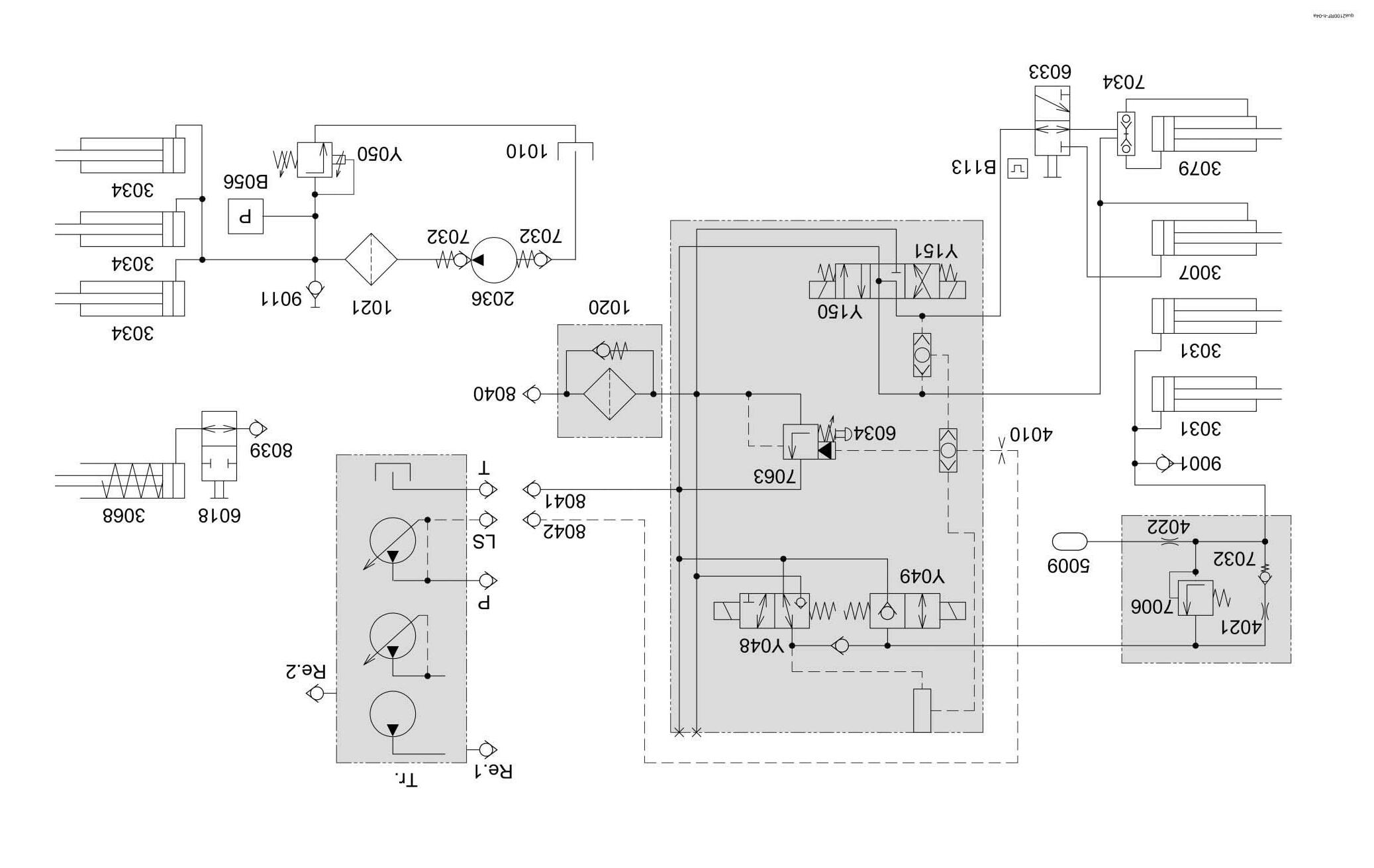
1.2.1 Quadrant 2100 RF overall hydraulic system circuit diagram - up to serial no. 741 00 325
1.2.2 Overall hydraulic system circuit diagram
Quadrant 2100 RF
from serial no. 741 00 326
(for machines equipped with a turbofan)
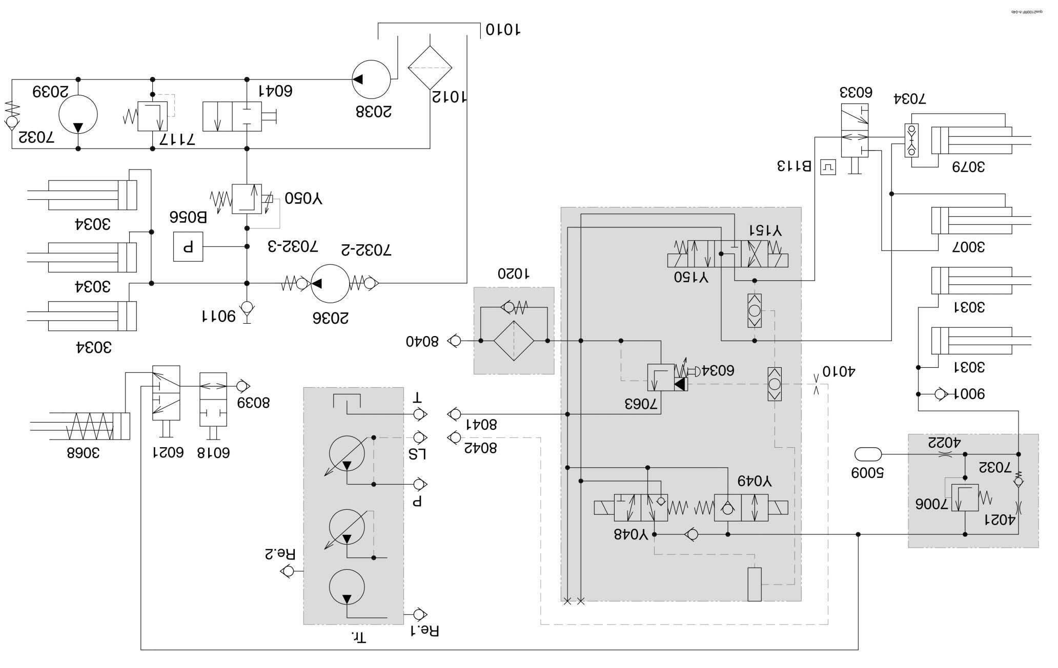
1.2.2 Quadrant 2100 RF overall hydraulic system circuit diagram - from serial no. 741 00 326 (for machines equipped with a turbofan)
1.2.3 Key to diagram:
1010 Oil tank (baling pressure hydraulic system) 1012 Return filter 1020 Pressure filter (working hydraulics) 1021 Pressure filter (baling pressure hydraulics)
2036 Baling pressure hydraulic system pump (1.5 l/min) 2038 Knotter fan pump 2039 Knotter fan motor
3007 Bale ejector hydraulic cylinder 3031 Pick-up hydraulic cylinder 3034 Baling chamber hydraulic cylinder 3068 Stand hydraulic cylinder
4010 Orifice plate (1.5 mm) 4021 Restrictor A 4022 Restrictor B
5009 Pick-up relief accumulator (45 bar)
6018 Tractor shut-off valve 6021 Jack stand / pick-up changeover valve 6033 Bale ejector / bale ramp reversing valve 6034 System screw 6041 Shut-off valve
7006 Pressure relief valve (80+ 5 bar) 7032 Non-return valve 7034 Lock-up valve unit 7063 Input pressure balance 7117 Knotter fan pressure relief valve (100 bar)
8039 Jack stand quick-release coupling 8040 Working hydraulics oil supply quick-release coupling 8041 Working hydraulics return line quick-release coupling 8042 LS connection, working hydraulics signal
9001 Working hydraulics measuring point (pick-up) 9011 Baling pressure measuring point
B056 Baling pressure sensor B113 Bale ejector / bale ramp function detection sensor
Y048 Pick-up raise solenoid coil Y049 Pick-up lower solenoid coil Y050 Baling pressure build-up solenoid coil 0 Volt = 150 bar (valve spring setting) Y150 Direction P ñ A reversing valve solenoid coil Y151 Direction P ñ B reversing valve solenoid valve
Tr. Tractor (all hydraulic systems are possible) Re.1 1st control valve / (oil supply, Qmax = approx. 50 l/min., Qmin = 42 l/min.) Re.2 2nd Control valve / (stand) P Port P / pump (in Power Beyond operation) T Port T / pressureless return line LS LS signal port (in Power Beyond operation)
1.2.4 Description of function: 1/3
Connection to tractor hydraulic system
The attachment can be connected to any tractor hydraulic system available on the market.
Connection to tractors with constant-flow hydraulic system or load-sensing system The quick release coupling 8040 is connected to a control unit port of the tractor with adjustable oil flow. This control unit provides oil supply for the attachment and is adjusted to a constant volume flow of Qmax = 50 l/min.
The system screw 6034 is turned out up to the stop so that the input pressure balance 7063 is operative.
The quick release coupling 8041 is in general connected to the pressureless return line T of the tractor. If a pressureless return line is not allowed in continuous operation (e.g. because lubrication of the tractor gearbox is not guaranteed), a double-acting control unit can be used for supplying oil to the attachment. In this case, the quick release coupling 8040 is connected to port A (feed) and quick release coupling 8041 to port B (return) of the corresponding tractor control valve.
Adjust the volume flow to Qmax = 50 l/min; please refer also to the tractor's Operating Manual, e.g. "Continuous operation of hydraulic motors".
The quick release coupling 8042 (LS, working hydraulics signal) is not used with this connection option.
If the tractor is not provided with a flow-adjustable control unit, the volume flow must not exceed 50 l/min.
Connection to tractors with constant-pressure hydraulic system The quick release coupling 8040 is connected to a control unit port of the tractor with adjustable oil flow. This control unit provides oil supply for the attachment and is adjusted to an oil flow of approx. Qmax = 50 l/min.
The system screw 6034 is turned in up to the stop so that the input pressure balance 7063 is blocked. The tractor's hydraulic pump is shut down when the system pressure has been reached.
The quick release coupling 8041 is connected to port T (pressureless return line) of the tractor.
The quick release coupling 8042 (LS, working hydraulics signal) is not used with this connection option.
Description of function: 2/3
Connection to tractors with load-sensing system and a Power Beyond port The quick release coupling 8040 is connected directly to the pump via the Power Beyond port P.
The quick release coupling 8041 is connected to port T (pressureless return line) of the tractor.
The quick release coupling 8042 (LS, working hydraulics signal) is connected to the tractor's "LS signal" port when using this connection option.
The system screw 6034 is turned in up to the stop so that the input pressure balance 7063 is blocked. The tractor's hydraulic pump regulates as a function of the attachment's load signal.
Test points / Characteristics When no function is active on the attachment, the attachment must not load the tractor hydraulically (The tractor engine speed must not be reduced). The allowed temperature of the tractor's hydraulic system must not be exceeded; see also the Operator's Manual of the tractor.
Connection to tractors with load-sensing system without a Power Beyond port The quick release coupling 8040 is connected to a control unit port of the tractor with adjustable oil flow. This control unit provides oil supply for the attachment and is adjusted to a constant volume flow of Qmax = 50 l/min.
The system screw 6034 is turned out up to the stop so that the input pressure balance 7063 is operative.
The quick release coupling 8041 is in general connected to the pressureless return line T of the tractor. If a pressureless return line is not allowed in continuous operation (e.g. because lubrication of the tractor gearbox is not guaranteed), a doubleacting control unit can be used for supplying oil to the attachment. In this case, the quick release coupling 8040 is connected to port A (feed) and quick release coupling 8041 to port B (return) of the corresponding tractor control valve.
Adjust the volume flow to Qmax = 50 l/min; please refer also to the tractor's Operating Manual, e.g. "Continuous operation of hydraulic motors".
The quick release coupling 8042 (LS, working hydraulics signal) is not used with this connection option.
If the tractor is not provided with a flow-adjustable control unit, the volume flow must not exceed 50 l/min.
Description of function: 3/3
Baling pressure hydraulic system As soon as the QUADRANT is mechanically driven, the baling pressure hydraulics pump 2036 pumps a constant oil flow into the baling chamber hydraulic cylinders 3034. The oil pressure in the baling chamber hydraulic cylinders 3034 is controlled by the baling pressure build-up solenoid coil Y050. To achieve this, the baling pressure build-up solenoid coil Y050 is actuated by the electronic unit using pulse-width modulation (PWM). When the baling pressure build-up solenoid coil Y050 is not energized, the maximum oil pressure is reached in the baling pressure hydraulic system. This pressure is set to 150 bar at the factory.
The baling pressure sensor B056 transmits a signal to the electronic unit which corresponds to the oil pressure. This pressure is displayed on the terminal.
The baling pressure measuring point 9011 can be used for measuring the pressure and for bleeding the baling pressure hydraulic system.
Working hydraulics When the solenoid coils Y048, Y145, Y150 and Y151 in the working hydraulics basic block are actuated, they transmit a load signal to the input pressure balance 7063 and to the tractor's LS signal port 8042. This is required for building up the oil pressure in the working hydraulics. (Exception: tractors with constant-pressure hydraulic systems); see also section "Connection to tractor hydraulic system".
When the solenoid coils Y142, Y147 and Y148 in the additional valve block are actuated, the solenoid coil Y150 or Y151 is actuated at the same time. The additional valve block is supplied with volume flow by the actuated solenoid coil Y150 or Y151.
Function of input pressure balance 7063 in constantflow operation The spring space of input pressure balance 7063 is relieved towards return line T when no working hydraulics function is activated. When volume flow is flowing, the pressure balance is opened against the spring. The volume flow flows from 8040 P to 8041 T with a low circulation pressure. When a function is activated which requires pressure build-up in the working hydraulics, a load signal is transmitted into the spring space of input pressure balance 7063. This load signal and the spring force control the pressure balance.
Pick-up hydraulic system When the pick-up is lowered, the volume flow flows out of the pick-up hydraulic cylinders 3031 across the pressure relief valve (80 bar) 7006. These 80 bar hold the pick-up in this working position, accumulator 5009 provides spring-type suspension.
The working hydraulics (pick-up) measuring point 9001 can be used for measuring the pressure and for venting of the pick-up hydraulic system.