18 minute read
Chapter 3 Valve components


3.1 Main valve block ñ without active hydraulic system........................36
3.2 Baling chamber service shut-off valve ñ without active hydraulic system.......................................................40
3.3 Lock-up valve unit (734)..................................................................44
3.4 Pressure relief valve (754), Baling pressure build-up solenoid valve (Y50) ñ without active hydraulic system..................46
3.5 Flow controllers (755, 756)..............................................................48
3.6 Rotor cut-out clutch..........................................................................50
3.7 ROTO CUT knife support IN/OUT solenoid valve (Y54/Y55)..........56 3.7.1 ROTO CUT knife support IN/OUT solenoid valve (Y54/Y55) from serial no.: 7300 2827...............................................................58
3.8 Main valve block ñ with active hydraulic system.............................60 3.8.1 Main valve block ñ with active hydraulic system (from serial no.: 7300 3039 V280, 7320 1875 V260)......................66
3.1 Main valve block ñ without active hydraulic system
Hydraulic circuit diagram
Key to diagram:
6 Valve block
102-2 Filter (series equipment)
626-C Shut-off tap for left-side tailgate cylinder Is combined with 626-D and 626-E.
626-D Shut-off tap for right-side tailgate cylinder. Is combined with 626-C and 626-E.
626-E Shut-off tap for belt tensioner cylinder. Is combined with 626-B and 626-C. - blocked when 626-C and 626-D are open. - open when 626-C and 626-D are blocked.
731-4 Non-return valve
734-1 734-2 Lock-up valve unit non-return valve shuts off the tailgate hydraulic cylinders (318), the rotor cut-out clutch (338) and the drive clutch (370).
754 Pressure relief valve maintains the pressure in the tensioning arm circuit at 10 bar.
755 Flow controller controls the volume flow for opening the tailgate to 50 l/min. The non-return valve does actually not exist ñ here it serves merely for better understanding of the circuit diagram.
756 Flow controller controls the volume flow for closing the tailgate to 18 l/min. The non-return valve does actually not exist ñ here it serves merely for better understanding of the circuit diagram.
Y50 Baling pressure build-up solenoid valve - limits the pressure in the tensioning arm circuit and thus controls the baling pressure. - is controlled by the electronic box (the desired baling pressure is set by a potentiometer). - when the power supply fails, the highest baling pressure is reached.
A - X Ports
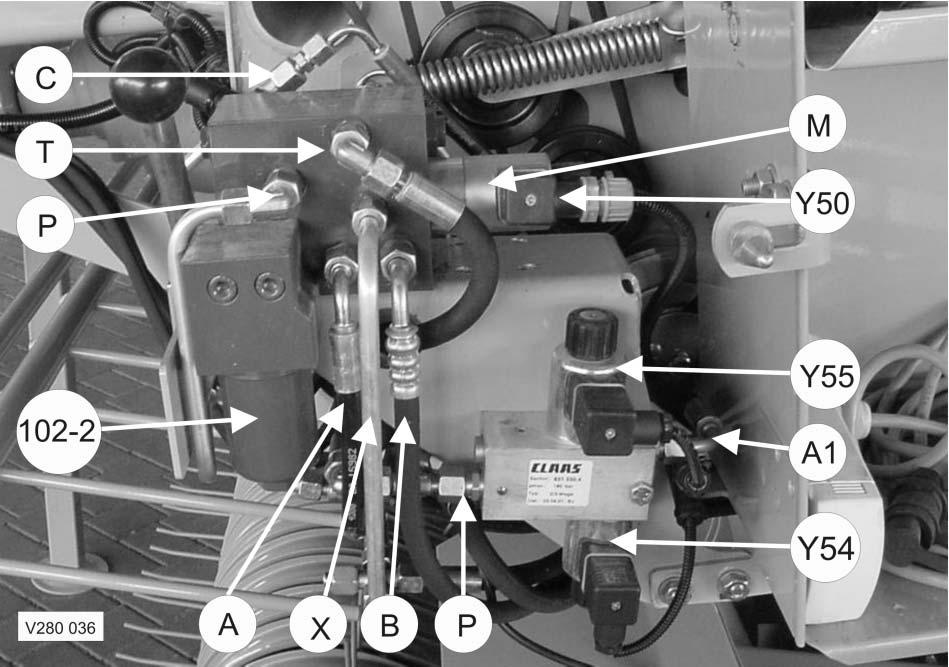
Key to diagram:
102-2 Filter (series equipment)
A Port To the piston top spaces of the tailgate cylinders
A1 Port To the knife support ON/OFF hydraulic cylinders
B Port To the piston top space of the tailgate cylinders
C Port To the rotor cut-out clutch (338) and drive clutch (370)
M Solenoid coil of Baling pressure build-up solenoid valve (Y50)
P Port Oil supply from tractor
T Port Tank (return to tractor)
X Port To the rod spaces of belt tensioner cylinders
Y50 Baling pressure build-up solenoid valve - limits the pressure in the tensioning arm circuit and thus controls the baling pressure. - is controlled by the electronic box (the desired baling pressure is set by a potentiometer). - when the power supply fails, the highest baling pressure is reached.
Y54 ROTOCUT knives OUT solenoid valve
Y55 ROTOCUT knives IN solenoid valve
3.2 Baling chamber service shut-off valve ñ without active hydraulic system
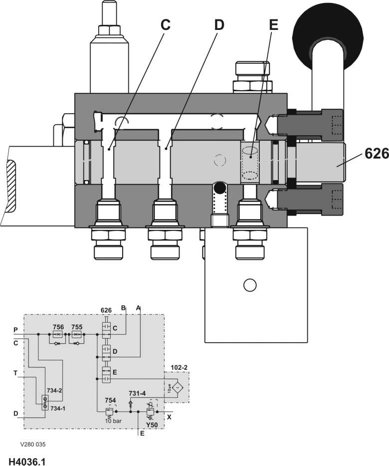
Key to diagram:
626 Baling chamber service shut-off valve
626-C Left tailgate cylinder shut-off valve 626-D Right tailgate cylinder shut-off valve 626-E Tensioning cylinder shut-off valve
Description of function:
The bale chamber service shut-off valve 626 is a rotary disc valve with the following valve functions: 626 C for the left tailgate cylinder 626 D for the right tailgate cylinder and 626 E for the belt tensioner cylinders
Hand lever position
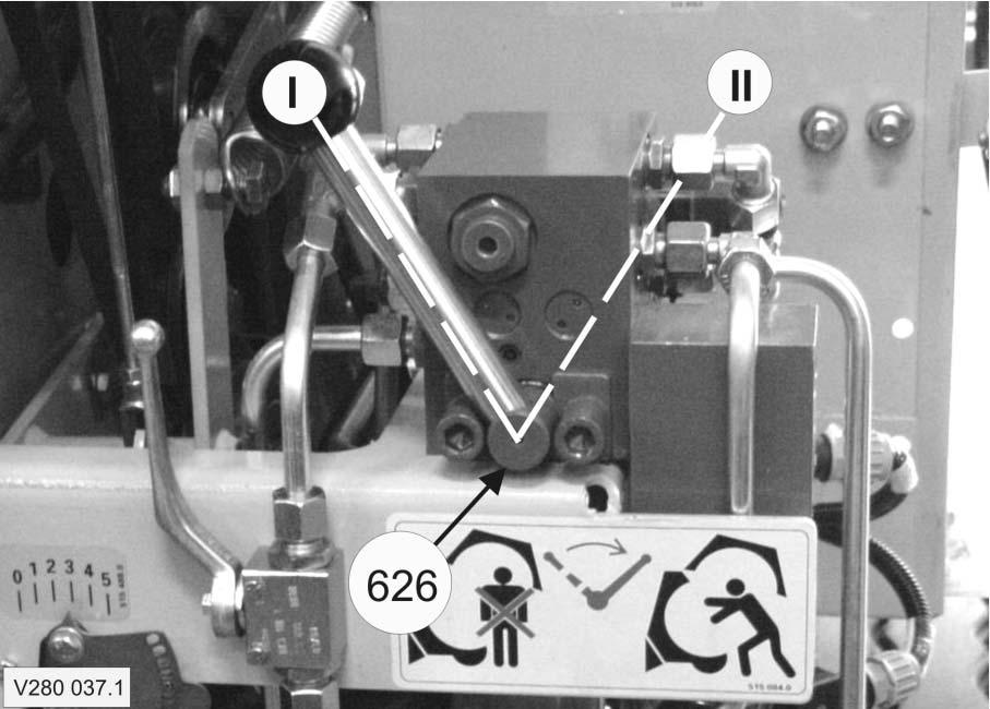
Key to diagram:
626 Baling chamber service shut-off valve
I, II Lever positions
Description of function:
Position I:
The shut-off valves (626 C and 626 D) provide a connection to the tailgate cylinders. The shut-off valve (626 E) has shut off the connection to the tensioning cylinders.
Position II: The shut-off valves (626 C and 626 D) have shut off the connection to the tailgate cylinders. The shut-off valve (626 E) has opened the connection to the tensioning cylinders.
3.3 Lock-up valve unit (734)
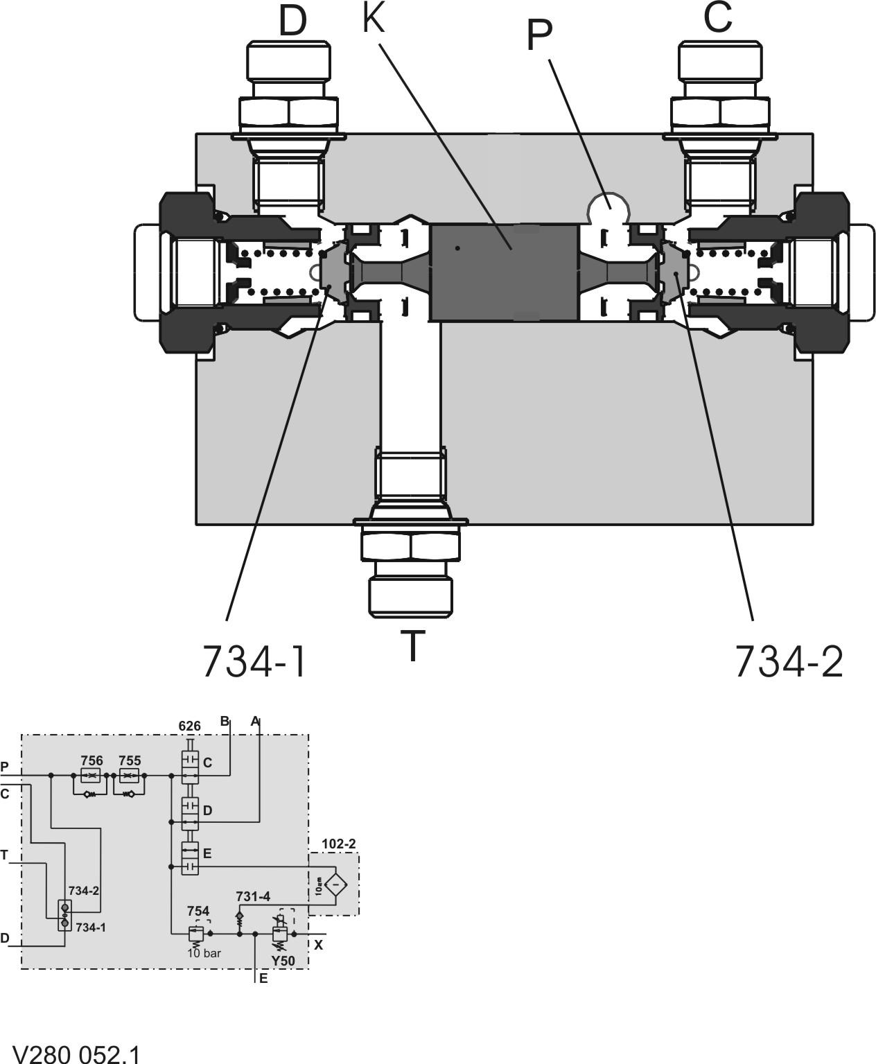
Key to diagram:
734-1 Lock-up valve unit non-return valve
734-2 Lock-up valve unit non-return valve
C Port
D Port
K Piston
P Port
T Port
Description of function:
Lock-up valve unit non-return valve (734-1)
Lock-up valve unit non-return valve (734-2) Blocks port (D) = to the rod spaces of tailgate cylinders (318-1 and 318-2).
Blocks port (C) = to the rotor cut-out clutch (338) and the drive clutch (370).
Port C Pressurized oil is applied here in case of: - rotor cut-out clutch (338) and drive clutch (370) are to be shut down - tailgate is to be opened
Port D To the rod spaces of tailgate cylinders (318-1 and 318-2). Pressurized oil when tailgate is to be closed.
Piston K Is moved to the left by pressure build-up in port (P). This opens the lock-up valve unit non-return valve (734-1).
Port P Oil supply from tractor. Pressurized oil when tailgate is to be opened.
Port T To tractor. Pressurized oil when tailgate is to be closed.
3.4 Pressure relief valve (754), Baling pressure build-up solenoid valve (Y50) ñ without active hydraulic system
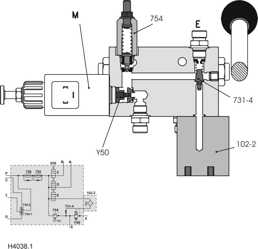
Key to diagram:
102-2 Filter
731-4 Non-return valve 754 Pressure relief valve
E Port
M Solenoid coil
Y50 Baling pressure build-up solenoid valve
Description of function:
Non-return valve (731-4) shuts off the pre-pressurizing circuit against the filter circuit.
Pressure relief valve (754) Maintains the pressure in the tensioning arm circuit at 10 bar.
Port (E) to the ram spaces of the tensioner cylinders.
Solenoid coil (M) Solenoid coil of Baling pressure build-up solenoid valve (Y50)
Baling pressure build-up solenoid valve (Y50) - limits the pressure in the tensioning arm circuit and thus controls the baling pressure. - Is actuated by the electronic box (the desired baling pressure is set with a potentiometer). - When power supply fails, the highest baling pressure is reached.
3.5 Flow controllers (755, 756)
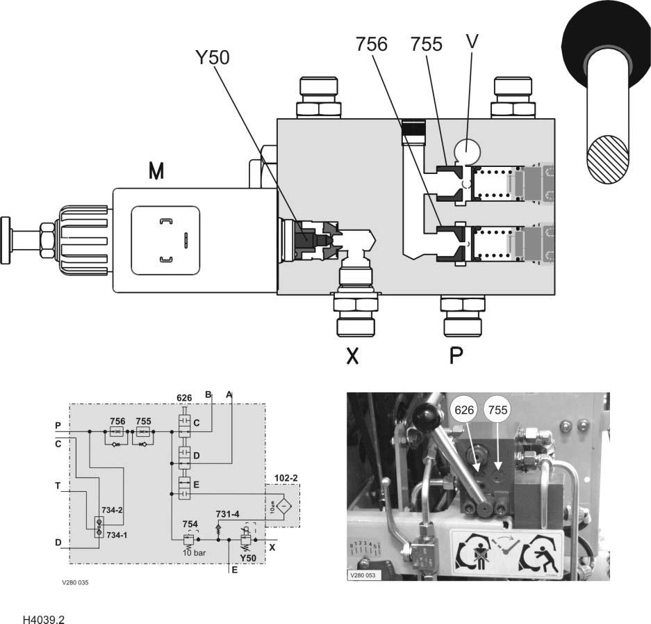
Key to diagram:
755 Flow controller
756 Flow controller
M
P, X Port
V Connection
Y50 Baling pressure build-up solenoid valve
Description of function:
Open tailgate: - Volume flow enters via port (P) and flows through flow controller (756) from the spring side; flow controller (756) does not control the flow. - Volume flow flows via the connecting channel to the face end of the flow controller (755). - The flow controller (755) controls the volume flow to 50 l/min. - The volume flow flows via port (V) to the rotary disc valve of the shutoff tap and continues into the piston top spaces of the tailgate cylinders.
Close tailgate: - Volume flow enters via port (V) and flows through flow controller (755) from the spring side; flow controller (755) does not control the flow. - Volume flow flows via the connecting channel to the face end of the flow controller (756). - The flow controller (756) controls the volume flow to 18 l/min. - The volume flow flows to the tractor via port (P).
Baling pressure build-up solenoid valve (Y50) - limits the pressure in the tensioning arm circuit and thus controls the baling pressure. - is controlled by the electronic box (the desired baling pressure is set by a potentiometer). - when the power supply fails, the highest baling pressure is reached.
3.6 Rotor cut-out clutch
Shut-off tap (627)

Key to diagram:
627 Rotor clutch / 2nd belt drive shut-off valve
P, P1 Port
KL Connection
Description of function:
Port K Connection to rotor cut-out clutch and drive clutch
Port P Shut-off tap output = P input into control unit (6)
Port P1 Connection to tractor. This port is located on the back side of the shut-off tap.
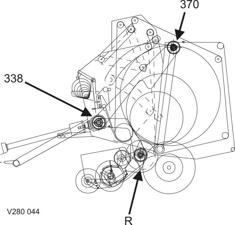
Key to diagram:
338 Rotor cut-out clutch
370 Roller 3 drive clutch
R Rotor
Description of function:
When rotor (R) is blocked, the rotor clutch (338) is shut off separately so that the rotor (R) can be rotated by hand.
Design and function
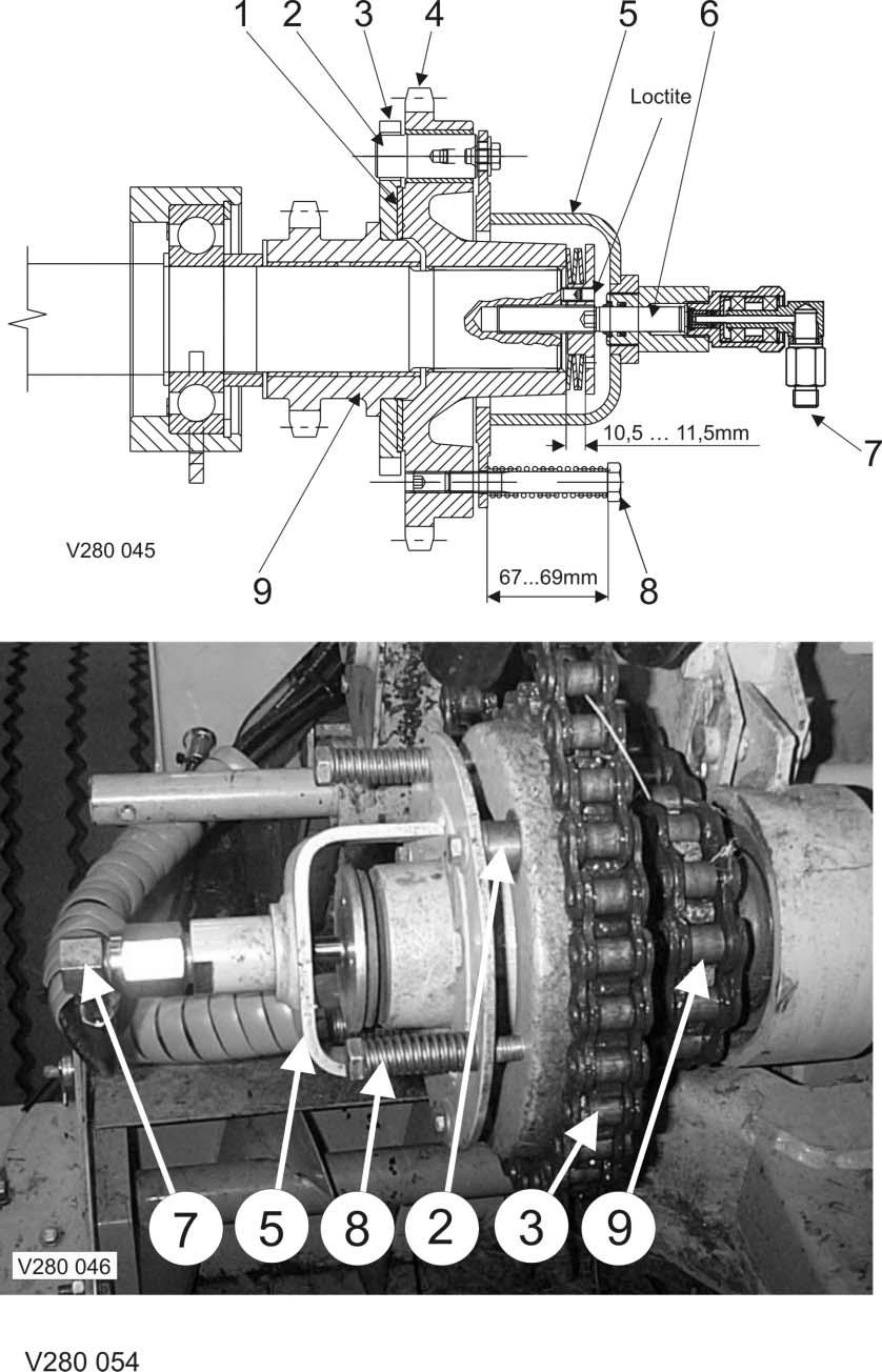
Key to diagram:
1 Friction disc
2 Bolts
3, 4 Sprocket
5 U-plate
6 Bolts
7 Port
8 Pressure spring
9 Sprocket
Description of function:
Friction disc (1) Ensures rotor rotation while clutch is disengaged. This avoids net damage.
Bolts (2) are bolted to the U-shaped sheet metal (5) and connect the sprockets (3 and 4) when the clutch is closed.
Sprocket (3) Is welded to sprocket (9).
Sprocket (4) Bale chamber drive
U-plate (5) - The bolts (2) are bolted here - Is loaded by the pressure springs (8) so that the bolts (2) remain engaged = clutch engaged.
Bolts (6) Is bolted to the transmission input shaft.
Port (7) Hydraulic connection to the shut-off valve and to the rotor cut-out clutch / 2nd belt drive (item 627, see circuit diagram).
Pressure spring (8) 3 pieces distributed around the circumference. They load the U-shaped sheet metal (5).
Sprocket (9) Pick-up rotor drive
Clutch disengage function Pressurized oil enters via port (7) and acts on the top side of bolt (6). The U-plate (5) performs a stroke of approx. 12 - 14 mm. As the bolts (2) are bolted to the U-plate, sprocket (4) is disengaged by sprocket (9). Sprocket (9) may be freely rotated on the bearing bushing.
Clutch engage function No pressurized oil in port (7). The compression springs (8) press on the bolts (6) connecting the two sprockets (4 and 9) with one another via the U-shaped sheet metal (5).
3.7 ROTO CUT knife support IN/OUT solenoid valve (Y54/Y55)
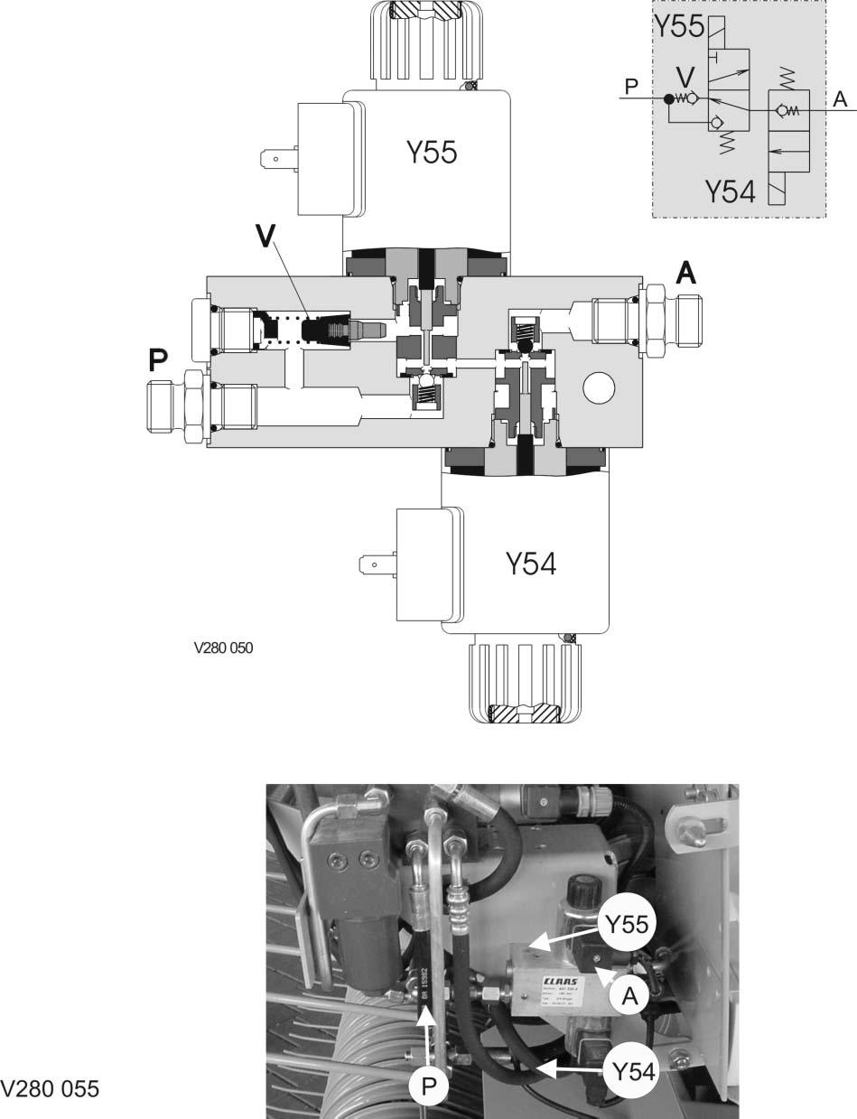
Key to diagram:
A ROTO CUT knife support IN/OUT hydraulic cylinder port
P Tractor port (single-acting control unit)
Y54 ROTO CUT knife support OUT solenoid valve
Y55 ROTO CUT knife support IN solenoid valve
Description of function:
Knife support ON Volume flow from the tractor enters via port (P). The ROTO CUT knife support IN solenoid valve (Y55) is energized. The pilot spool of the 2/3-way valve opens the ball so the volume flow flows to the 2/3-way valve (Y54). The ball of the 2/3-way valve (Y54) is opened by pressure build-up. The volume flow flows via port (A) to the hydraulic cylinders which swing in the knife support.
Knife support OFF The tractor control unit is set to floating position. The solenoid of the 2/3-way valve (Y54) is actuated. The pilot spool of the 2/3-way valve (Y54) opens the ball. Since the knife support hydraulic cylinders are loaded by the baled material, volume flow flows via port (A) and via the open ball of the 2/3-way valve (Y54)to the 2/3-way valve (Y55). The volume flow flows via the non-return valve (V) to port (P) and further to the tractor (tank).
Note: When disassembling or replacing a valve insert, the sealing ring must always be replaced, too. Rubber-coated aluminium ring for aluminium valve bodies, copper ring for steel valve bodies.
The rubber-coated aluminium ring cannot be replaced by a copper ring and vice versa.
3.7.1 ROTO CUT knife support IN/OUT solenoid valve (Y54/Y55) from serial no.: 7300 2827

Key to diagram:
A ROTO CUT knife support IN/OUT hydraulic cylinder port
P Tractor port (single-acting control unit)
Y54 ROTO CUT knife support OUT solenoid valve
Y55 ROTO CUT knife support IN solenoid valve
Description of function:
Knife support ON Volume flow from the tractor enters via port (P). The ROTO CUT knife support IN solenoid valve (Y55) is energized. The pilot spool of the 2/3-way valve opens the ball so the volume flow flows to the 2/3-way valve (Y54). The ball of the 2/3-way valve (Y54) is opened by pressure build-up. The volume flow flows via port (A) to the hydraulic cylinders which swing in the knife support.
Knife support OFF The tractor control unit is set to floating position. The solenoid of the 2/3-way valve (Y54) is actuated. The pilot spool of the 2/3-way valve (Y54) opens the ball. Since the knife support hydraulic cylinders are loaded by the baled material, volume flow flows via port (A) and via the open ball of the 2/3-way valve (Y54) to the 2/3-way valve (Y55).
3.8 Main valve block ñ with active hydraulic system

Key to diagram:
626 Shut-off tap 732-4 Non-return valve 734-1 Lock-up valve unit (non-return valve) 734-2 Lock-up valve unit (non-return valve) 755 Flow controller 756 Flow controller Y50 Baling pressure solenoid valve
A Consumer port B Consumer port P Pump port T Tank port
Description of function:
Closing the tailgate - with active hydraulic system 1. The pilot-controlled non-return valves (732-5 and 732-6) reliably seal off the tailgate cylinders. This is particularly important when performing service work while the tailgate is open. The tailgate can be closed only by building up pressure in port (801-2 B).
2. Via port (801-2 B), oil also flows into the rod spaces of hydraulic cylinders (345, 346-1 and 346-2) in order to retract the hydraulic cylinders quickly ñ the belts are tensioned. To this end, the non-return valves (732-1 and 732-2) are opened by the oil flow.
The oil is applied at port X of the Baling pressure build-up solenoid valve (Y55) which is electronically regulated to 90 bar during the tailgate closing process.
The oil displaced from the ram spaces of hydraulic cylinders (345, 346-1 and 346-2) is drained via the non-return valve (732-3), the shut-off tap (627) and port A.
Baling Baled material pulls the hydraulic cylinders (346-1, 346-2 and 345) to the outside by means of the tensioning arms. Baling pressure is thus built up in the rod spaces of these cylinders; this pressure can be read at pressure gauge (912). The baling pressure enters valve block (6) at inlet (X) and is applied to the Baling pressure build-up valve (Y50). When the set baling pressure has been reached, the Baling pressure build-up solenoid valve (Y50) opens, making oil flow via port (E) into the ram sides of hydraulic cylinders (346-1, 346-2 and 345). The hydraulic accumulator (513) compensates the volumetric difference between the cylinder sides.
Opening the tailgate - without active hydraulic system Oil flows into valve block 6 (port P) via port (801-2 A), filter (102-1) and the rotor clutch / 2nd belt drive shut-off tap (627). Oil flows via the open shut-off taps (626C and 626D) into the ram spaces of hydraulic cylinders (318-1 and 318-2), via ports (A and B) and the nonreturn valves (732-5 and 732-6). During this process, the flow rate is regulated to 50 l/min. by the flow controllers (756 and 755). At the same time, the lubricating oil pump (232) is supplied. Pressurized oil is tapped directly downstream of inlet (P) of valve block (6) which opens the lock-up valve unit non-return valve (734-1) via a ram. The oil displaced from the rod spaces of hydraulic cylinders (318-1 and 318-2) flows through the open lock-up valve unit non-return valve (734-1) and port (T) to the quick release coupling (801-2 B). Downstream of the rotor clutch / 2nd belt drive shut-off tap (627), pressurized oil flows to the rotor cut-out clutch (338) and to the drive clutch (370) for roller 3. The clutches open so that the rotor and the drive of roller 3 are switched off while the tailgate is opened.
Opening the tailgate - with active hydraulic system As early as when opening the tailgate, the pressure rises to above 90 bar. Pressure switch (Z17) closes. With this signal, the module regulates the Baling pressure build-up solenoid valve (Y50) to 0 bar. Now the rod spaces of hydraulic cylinders (345, 346-1 and 346-2) are pressureless and the belts are relieved ñ opening the tailgate is accelerated.
Relieving the belts (for maintenance work in the baling chamber) 1. Switch on control box (baler CCT) so the Baling pressure build-up solenoid valve (Y50) is energized.
2. Disengage the p.t.o. shaft.
3. Open the tailgate as far as necessary and secure it.
4. Actuate the shut-off valve (626):
The shut-off taps (626 C) and (626 D) of the tailgate are now blocked and shut-off tap (626 E) is open. Oil flows into valve block 6 (port P) via port (801-2 A), filter (102-1) and shut-off tap (627). Oil continues to flow via filter (102-2), non-return valve (732-4) and port (E) into the ram spaces of hydraulic cylinders (346-1, 346-2 and 345) through the open shut-off tap (626 E). The cylinders extend and the belts are relieved. The oil displaced from the rod spaces of hydraulic cylinders (346-1, 346-2 and 345) flows to the Baling pressure build-up solenoid valve (Y50) via port (X). This valve is electronically regulated to 0 bar when the tailgate is open and oil may therefore flow freely through it. The rod spaces and the ram spaces of the belt tensioner cylinders (346-1, 346-2 and 345) are now connected with each other. There is the same pressure in both cylinder spaces, but since the greater force is generated on the ram surface, the cylinders extend and relieve the belts.
Tensioning the belts The baling chamber service shut-off valve still is in the "Tailgate blocked" position; now the double-acting control unit provided on the tractor is set to the "Lower" position. The hydraulic cylinders (346-1, 346-2 and 345) are retracted by springs on the left baler side. When maintenance work is complete, the tailgate is closed and the belts must be driven during closing. Otherwise there is a risk of the belts being squeezed.
- with active hydraulic system The oil displaced from the ram spaces during this process flows into the tank via non-return valve (732-3), shut-off tap (627) and port (801-2 A).
3.8.1 Main valve block ñ with active hydraulic system (from serial no.: 7300 3039 V280, 7320 1875 V260)

Key to diagram:
626 Shut-off tap 732-3 Non-return valve 732-4 Non-return valve 734-1 Lock-up valve unit (non-return valve) 734-2 Lock-up valve unit (non-return valve) 755 Flow controller 756 Flow controller Y50 Baling pressure solenoid valve
Z17 Pressure switch (70 bar)
A Consumer port B Consumer port P Pump port T Tank port
Description of function:
Closing the tailgate - with active hydraulic system 1. The pilot-controlled non-return valves (732-5 and 732-6) reliably seal off the tailgate cylinders. This is particularly important when performing service work while the tailgate is open. The tailgate can be closed only by building up pressure in port (801-2 B).
2. Via port (801-2 B), oil also flows into the rod spaces of hydraulic cylinders (345, 346-1 and 346-2) in order to retract the hydraulic cylinders quickly ñ the belts are tensioned. To this end, the non-return valves (732-1 and 732-2) are opened by the oil flow.
The oil is applied at port X of the Baling pressure build-up solenoid valve (Y55) which is electronically regulated to 90 bar during the tailgate closing process.
The oil displaced from the ram spaces of hydraulic cylinders (345, 346-1 and 346-2) is drained via the non-return valve (732-3), the shut-off tap (627) and port A.
Baling Baled material pulls the hydraulic cylinders (346-1, 346-2 and 345) to the outside by means of the tensioning arms. Baling pressure is thus built up in the rod spaces of these cylinders; this pressure can be read at pressure gauge (912). The baling pressure enters valve block (6) at inlet (X) and is applied to the Baling pressure build-up valve (Y50). When the set baling pressure has been reached, the Baling pressure build-up solenoid valve (Y50) opens, making oil flow via port (E) into the ram sides of hydraulic cylinders (346-1, 346-2 and 345). The hydraulic accumulator (513) compensates the volumetric difference between the cylinder sides.
Opening the tailgate - with active hydraulic system As early as when opening the tailgate, the pressure rises to above 70 bar. Pressure switch (Z17) closes. With this signal, the module regulates the Baling pressure build-up solenoid valve (Y50) to 0 bar. Now the rod spaces of hydraulic cylinders (345, 346-1 and 346-2) are pressureless and the belts are relieved ñ opening the tailgate is accelerated.
Relieving the belts (for maintenance work in the baling chamber) 1. Switch on control box (baler CCT) so the Baling pressure build-up solenoid valve (Y50) is energized.
2. Disengage the p.t.o. shaft.
3. Open the tailgate as far as necessary and secure it.
4. Actuate the shut-off valve (626):
The shut-off taps (626 C) and (626 D) of the tailgate are now blocked and shut-off tap (626 E) is open. Oil flows into valve block 6 (port P) via port (801-2 A), filter (102-1) and shut-off tap (627). Oil continues to flow via filter (102-2), non-return valve (732-4) and port (E) into the ram spaces of hydraulic cylinders (346-1, 346-2 and 345) through the open shut-off tap (626 E). The cylinders extend and the belts are relieved. The oil displaced from the rod spaces of hydraulic cylinders (346-1, 346-2 and 345) flows to the Baling pressure build-up solenoid valve (Y50) via port (X). This valve is electronically regulated to 0 bar when the tailgate is open and oil may therefore flow freely through it. The rod spaces and the ram spaces of the belt tensioner cylinders (346-1, 346-2 and 345) are now connected with each other. There is the same pressure in both cylinder spaces, but since the greater force is generated on the ram surface, the cylinders extend and relieve the belts.
Tensioning the belts The baling chamber service shut-off valve still is in the "Tailgate blocked" position; now the double-acting control unit provided on the tractor is set to the "Lower" position. The hydraulic cylinders (346-1, 346-2 and 345) are retracted by springs on the left baler side. When maintenance work is complete, the tailgate is closed and the belts must be driven during closing. Otherwise there is a risk of the belts being squeezed.
- with active hydraulic system The oil displaced from the ram spaces during this process flows into the tank via non-return valve (732-3), shut-off tap (627) and port (801-2 A).