23 minute read
Chapter 2 Function


2.1 Function ñ without active hydraulic system.....................................18
2.2 Function ñ with active hydraulic system, with integrated pressure holding valve (754) up to serial no...........22
2.3 Function ñ with active hydraulic system, without integrated pressure holding valve (754) from serial no.......26
2.4 Function ñ with active hydraulic system, main valve block 039 866.0 from serial no. 7300 3039 (V280), 7320 1875 (V260).....................30
2.1 Function ñ without active hydraulic system
Description of function:
Close tailgate Volume flow enters the valve block (6, port T) via port (801-2 B) and flows to the lock-up valve unit non-return valve (734-1). The lock-up valve unit is opened. Pressurized oil flows into the rod spaces of hydraulic cylinders (318-1 and 318-2) via the opened lock-up valve unit non-return valve (734-1) and port D. The volume flow displaced from the ram spaces of hydraulic cylinders (318-1 and 318-2) flows into the tank via the shut-off taps (626 C and D), the flow controllers (756 and 755), the shut-off tap (627) and filter (102-1). The flow controller controls the returning volume flow to 18 l/min., making the tailgate closing velocity lower than the opening velocity.
Baling Baled material pulls the hydraulic cylinders (346-1, 346-2 and 345) to the outside by means of the tensioning arms. This builds up baling pressure in the rod spaces of these cylinders. The pressure can be read on pressure gauge (912 baling pressure). The baling pressure enters valve block (6) via input (X). The baling pressure is applied at the baling pressure build-up solenoid valve (Y50). When the set baling pressure has been reached, the baling pressure build-up solenoid valve (Y50) opens, making volume flow flow via port (E) into the ram sides of hydraulic cylinders (346-1, 346-2 and 345). The hydraulic accumulator (513) compensates the volumetric difference.
Open tailgate Volume flow flows into valve block 6 (port P) via port (801-2 A), filter (102-1) and the rotor clutch / 2nd belt drive shut-off tap (627). The volume flow flows via the open shut-off taps (626C and 626D) into the ram spaces of hydraulic cylinders (318-1 and 318-2), via ports (A and B). During this process, the flow rate is regulated to 50 l/min. by the flow controllers (756 and 755). At the same time, the lubricating oil pump (232) is supplied. Pressurized oil is tapped directly downstream of inlet (P) of valve block (6), making the lock-up valve unit non-return valve (734-1) open. The volume flow displaced from the rod spaces of hydraulic cylinders (318-1 and 318-2) flows through the open lock-up valve unit non-return valve (734-1) and port (T) to the quick release coupling (801-2 B). Downstream of the rotor clutch / 2nd belt drive shut-off tap (627), pressurized oil flows to the rotor cut-out clutch (338) and to the drive clutch (370) for roller 3. The clutches open so that the rotor and the drive of roller 3 are switched off while the tailgate is opened.
Relieving the belts during maintenance work in the baling chamber - Switch on control box (baler CCT) so the baling pressure build-up solenoid valve (Y50) is energized. - Disengage the p.t.o. shaft. - Open the tailgate as far as necessary and secure it. - Actuate the baling chamber service shut-off valve (626):
The shut-off taps (626 C) and (626 D) of the tailgate are now shut off and the shut-off tap (626 E) is open. Oil flows into valve block 6 (port P) via port (801-2 A), filter (102-1) and the rotor clutch / 2nd belt drive shut-off tap (627). Volume flow continues to flow via filter (102-2), non-return valve (731-4) and port (E) into the ram spaces of hydraulic cylinders (346-1, 346-2 and 345) through the open shut-off tap (626 E). The cylinders extend and the belts are relieved. The volume flow displaced from the rod spaces of hydraulic cylinders (346-1, 346-2 and 345) flows to the baling pressure build-up solenoid valve (Y50) via port (X). This valve is electronically regulated to 0 bar when the tailgate is open and oil may therefore flow freely through it. The rod spaces and the ram spaces of the belt tensioner cylinders (346-1, 346-2 and 345) are now connected with each other. There is the same pressure in both cylinder spaces, but since the greater force is generated on the ram surface (greater by the force of the rod surface), the cylinders extend and relieve the belts.
Tensioning the belts The baling chamber service shut-off valve still is in the "Tailgate blocked" position; now the double-acting control unit provided on the tractor is set to the "Lower" position The hydraulic cylinders (346-1, 346-2 and 345) are retracted by springs on the left baler side. The volume flow displaced from the ram spaces flows via port (E) and uses two different paths, depending on the pressure: - when the pressure is above 10 bar, it flows into the tank via the pressure relief valve (754), the flow controllers (756 and 755), port (P) and port (801-2 A). - when the pressure is below 10 bar, the non-return valves (722-1, 722-2 and 722-3) open and provide volumetric compensation so that the tensioning arms can return to their initial position faster.
Swinging in the knife support When maintenance work is finished, the tailgate is closed; during this, the belts must be driven so that they will not be squeezed.
When actuating the "Swing in knife support" button, the 2/3 way directional control valve (Y55) "ROTOCUT knives IN" is energized. Volume flow flows into the ROTOCUT knives hydraulic cylinders (336) via port (801-1) and the energized 2/3 way valve. The ROTOCUT knives hydraulic cylinders (336) extend and swing in the knife support. The extended ROTOCUT knives hydraulic cylinders (336) are kept in their position by the non-return valve inside the 2/3 directional control valve (Y54).
Swinging out the knife support The single-acting tractor control unit is set to the "Lower" position ñ port (801-1) is connected to the tank. When actuating the "Swing out knife support" button, the 2/3 way directional control valve (Y54) is energized. The baled material loads the ROTOCUT knives hydraulic cylinders (336), making volume flow flow into the tank from the ram spaces via the energized 2/3 way valve (Y54), the unenergized 2/3 way valve (Y55) and port (801-1).
2.2 Function ñ with active hydraulic system, with integrated pressure holding valve (754) up to serial no. ...

Description of function:
Closing the tailgate - without active hydraulic system Oil enters the valve block (6, port T) via port (801-2 B) and opens the lock-up valve unit non-return valve (734-1). Via port D, the pressurized oil flows to the non-return valves (732-5 and 732-6) which are unlocked. The pressurized oil flows on into the rod spaces of hydraulic cylinders (318-1 and 318-2). The tailgate is closed. The oil displaced from the ram spaces of hydraulic cylinders (318-1 and 318-2) flows via the unblocked non-return valves (732-5 and 732-6), the shut-off taps (626 C and 626 D), the flow controllers (755 and 756), the shut-off tap (627) and filter (102-1) into the tank. The flow controllers (755 und 756) regulate the oil flow to 18 l/min. which reduces the closing time of the tailgate as compared with the opening time.
Closing the tailgate - with active hydraulic system 1. The pilot-controlled non-return valves (732-5 and 732-6) reliably seal off the tailgate cylinders. This is particularly important when performing service work while the tailgate is open. The tailgate can be closed only by building up pressure in port (801-2 B).
2. Via port (801-2 B), oil also flows into the rod spaces of hydraulic cylinders (345, 346-1 and 346-2) in order to retract the hydraulic cylinders quickly ñ the belts are tensioned. To this end, the non-return valves (732-1 and 732-2) are opened by the oil flow.
The oil is applied at port X of the Baling pressure build-up solenoid valve (Y55) which is electronically regulated to 90 bar during the tailgate closing process.
The oil displaced from the ram spaces of hydraulic cylinders (345, 346-1 and 346-2) is drained via the non-return valve (732-3), the shut-off tap (627) and port A. The pressure relief valve (754) is mechanically blocked = no function.
Baling Baled material pulls the hydraulic cylinders (346-1, 346-2 and 345) to the outside by means of the tensioning arms. Baling pressure is thus built up in the rod spaces of these cylinders; this pressure can be read at pressure gauge (912). The baling pressure enters valve block (6) at inlet (X) and is applied to the Baling pressure build-up valve (Y50). When the set baling pressure has been reached, the Baling pressure build-up solenoid valve (Y50) opens, making oil flow via port (E) into the ram sides of hydraulic cylinders (346-1, 346-2 and 345). The hydraulic accumulator (513) compensates the volumetric difference between the cylinder sides.
Opening the tailgate - without active hydraulic system Oil flows into valve block 6 (port P) via port (801-2 A), filter (102-1) and the rotor clutch / 2nd belt drive shut-off tap (627). Oil flows via the open shut-off taps (626C and 626D) into the ram spaces of hydraulic cylinders (318-1 and 318-2), via ports (A and B) and the nonreturn valves (732-5 and 732-6). During this process, the flow rate is regulated to 50 l/min. by the flow controllers (756 and 755). At the same time, the lubricating oil pump (232) is supplied. Pressurized oil is tapped directly downstream of inlet (P) of valve block (6) which opens the lock-up valve unit non-return valve (734-1) via a ram. The oil displaced from the rod spaces of hydraulic cylinders (318-1 and 318-2) flows through the open lock-up valve unit non-return valve (734-1) and port (T) to the quick release coupling (801-2 B). Downstream of the rotor clutch / 2nd belt drive shut-off tap (627), pressurized oil flows to the rotor cut-out clutch (338) and to the drive clutch (370) for roller 3. The clutches open so that the rotor and the drive of roller 3 are switched off while the tailgate is opened.
Opening the tailgate - with active hydraulic system As early as when opening the tailgate, the pressure rises to above 90 bar. The pressure switch (Z17) opens. With this signal, the module regulates the Baling pressure build-up solenoid valve (Y50) to 0 bar. Now the rod spaces of hydraulic cylinders (345, 346-1 and 346-2) are pressureless and the belts are relieved ñ opening the tailgate is accelerated.
Relieving the belts (for maintenance work in the baling chamber) 1. Switch on control box (baler CCT) so the Baling pressure build-up solenoid valve (Y50) is energized.
2. Disengage the p.t.o. shaft.
3. Open the tailgate as far as necessary and secure it.
4. Actuate the shut-off valve (626):
The shut-off taps (626 C) and (626 D) of the tailgate are now blocked and shut-off tap (626 E) is open. Oil flows into valve block 6 (port P) via port (801-2 A), filter (102-1) and shut-off tap (627). Oil continues to flow via filter (102-2), non-return valve (732-4) and port (E) into the ram spaces of hydraulic cylinders (346-1, 346-2 and 345) through the open shut-off tap (626 E). The cylinders extend and the belts are relieved. The oil displaced from the rod spaces of hydraulic cylinders (346-1, 346-2 and 345) flows to the Baling pressure build-up solenoid valve (Y50) via port (X). This valve is electronically regulated to 0 bar when the tailgate is open and oil may therefore flow freely through it. The rod spaces and the ram spaces of the belt tensioner cylinders (346-1, 346-2 and 345) are now connected with each other. There is the same pressure in both cylinder spaces, but since the greater force is generated on the ram surface, the cylinders extend and relieve the belts.
Tensioning the belts The baling chamber service shut-off valve still is in the "Tailgate blocked" position; now the double-acting control unit provided on the tractor is set to the "Lower" position. The hydraulic cylinders (346-1, 346-2 and 345) are retracted by springs on the left baler side. When maintenance work is complete, the tailgate is closed and the belts must be driven during closing. Otherwise there is a risk of the belts being squeezed.
- with active hydraulic system The oil displaced from the ram spaces during this process flows into the tank via non-return valve (732-3), shut-off tap (627) and port (801-2 A). The pressure relief valve (754) is mechanically blocked = no function.
Swinging in the knife support
Swinging out the knife support When actuating the "Swing in knife support" button, the 2/3 way directional control valve (Y55) "ROTOCUT knives IN" is energized. Oil flows into the ROTOCUT knives hydraulic cylinders (336) via port (801-1) and the energized 2/3 way valve. The ROTOCUT knives hydraulic cylinders (336) extend and swing in the knife support. The extended ROTOCUT knives hydraulic cylinders (336) are kept in their position by the non-return valve inside the 2/3 directional control valve (Y54).
The single-acting tractor control unit is set to the "Lower" position ñ port (801-1) is connected to the tank. When actuating the "Swing out knife support" button, the 2/3 way directional control valve (Y54) is energized. The baled material loads the ROTOCUT knives hydraulic cylinders (336), making oil flow into the tank from the ram spaces via the energized 2/3 way valve (Y54), the unenergized 2/3 way valve (Y55) and port (801-1).
2.3 Function ñ with active hydraulic system, without integrated pressure holding valve (754) from serial no.

Description of function:
Closing the tailgate - without active hydraulic system Oil enters the valve block (6, port T) via port (801-2 B) and opens the lock-up valve unit non-return valve (734-1). Via port D, the pressurized oil flows to the non-return valves (732-5 and 732-6) which are unlocked. The pressurized oil flows on into the rod spaces of hydraulic cylinders (318-1 and 318-2). The tailgate is closed. The oil displaced from the ram spaces of hydraulic cylinders (318-1 and 318-2) flows via the unblocked non-return valves (732-5 and 732-6), the shut-off taps (626 C and 626 D), the flow controllers (755 and 756), the shut-off tap (627) and filter (102-1) into the tank. The flow controllers (755 and 756) regulate the oil flow to 18 l/min. which reduces the closing time of the tailgate as compared with the opening time.
Closing the tailgate - with active hydraulic system 1. The pilot-controlled non-return valves (732-5 and 732-6) reliably seal off the tailgate cylinders. This is particularly important when performing service work while the tailgate is open. The tailgate can be closed only by building up pressure in port (801-2 B).
2. Via port (801-2 B), oil also flows into the rod spaces of hydraulic cylinders (345, 346-1 and 346-2) in order to retract the hydraulic cylinders quickly ñ the belts are tensioned. To this end, the non-return valves (732-1 and 732-2) are opened by the oil flow.
The oil is applied at port X of the Baling pressure build-up solenoid valve (Y55) which is electronically regulated to 90 bar during the tailgate closing process.
The oil displaced from the ram spaces of hydraulic cylinders (345, 346-1 and 346-2) is drained via the non-return valve (732-3), the shutoff tap (627) and port A.
Baling Baled material pulls the hydraulic cylinders (346-1, 346-2 and 345) to the outside by means of the tensioning arms. Baling pressure is thus built up in the rod spaces of these cylinders; this pressure can be read at pressure gauge (912). The baling pressure enters valve block (6) at inlet (X) and is applied to the Baling pressure build-up valve (Y50). When the set baling pressure has been reached, the baling pressure build-up solenoid valve (Y50) opens, making oil flow via port (E) into the ram sides of hydraulic cylinders (346-1, 346-2 and 345). The hydraulic accumulator (513) compensates the volumetric difference between the cylinder sides.
Opening the tailgate - without active hydraulic system Oil flows into valve block 6 (port P) via port (801-2 A), filter (102-1) and the rotor clutch / 2nd belt drive shut-off tap (627). Oil flows via the open shut-off taps (626C and 626D) into the ram spaces of hydraulic cylinders (318-1 and 318-2), via ports (A and B) and the nonreturn valves (732-5 and 732-6). During this process, the flow rate is regulated to 50 l/min. by the flow controllers (756 and 755). At the same time, the lubricating oil pump (232) is supplied. Pressurized oil is tapped directly downstream of inlet (P) of valve block (6) which opens the lock-up valve unit non-return valve (734-1) via a ram. The oil displaced from the rod spaces of hydraulic cylinders (318-1 and 318-2) flows through the open lock-up valve unit non-return valve (734-1) and port (T) to the quick release coupling (801-2 B). Downstream of the rotor clutch / 2nd belt drive shut-off tap (627), pressurized oil flows to the rotor cut-out clutch (338) and to the drive clutch (370) for roller 3. The clutches open so that the rotor and the drive of roller 3 are switched off while the tailgate is opened.
Opening the tailgate - with active hydraulic system As early as when opening the tailgate, the pressure rises to above 90 bar. The pressure switch (Z17) opens. With this signal, the module regulates the Baling pressure build-up solenoid valve (Y50) to 0 bar. Now the rod spaces of hydraulic cylinders (345, 346-1 and 346-2) are pressureless and the belts are relieved ñ opening the tailgate is accelerated.
Relieving the belts (for maintenance work in the baling chamber) 1. Switch on control box (baler CCT) so the Baling pressure build-up solenoid valve (Y50) is energized.
2. Disengage the p.t.o. shaft.
3. Open the tailgate as far as necessary and secure it.
4. Actuate the shut-off valve (626):
The shut-off taps (626 C) and (626 D) of the tailgate are now blocked and shut-off tap (626 E) is open. Oil flows into valve block 6 (port P) via port (801-2 A), filter (102-1) and shut-off tap (627). Oil continues to flow via filter (102-2), non-return valve (732-4) and port (E) into the ram spaces of hydraulic cylinders (346-1, 346-2 and 345) through the open shut-off tap (626 E). The cylinders extend and the belts are relieved. The oil displaced from the rod spaces of hydraulic cylinders (346-1, 346-2 and 345) flows to the Baling pressure build-up solenoid valve (Y50) via port (X). This valve is electronically regulated to 0 bar when the tailgate is open and oil may therefore flow freely through it. The rod spaces and the ram spaces of the belt tensioner cylinders (346-1, 346-2 and 345) are now connected with each other. There is the same pressure in both cylinder spaces, but since the greater force is generated on the ram surface, the cylinders extend and relieve the belts.
Tensioning the belts The baling chamber service shut-off valve still is in the "Tailgate blocked" position; now the double-acting control unit provided on the tractor is set to the "Lower" position. The hydraulic cylinders (346-1, 346-2 and 345) are retracted by springs on the left baler side. When maintenance work is complete, the tailgate is closed and the belts must be driven during closing. Otherwise there is a risk of the belts being squeezed.
- with active hydraulic system The oil displaced from the ram spaces during this process flows into the tank via non-return valve (732-3), shut-off tap (627) and port (801-2 A). The pressure relief valve (754) is mechanically blocked = no function.
Swinging in the knife support
Swinging out the knife support When actuating the "Swing in knife support" button, the 2/3 way directional control valve (Y55) "ROTOCUT knives IN" is energized. Oil flows into the ROTOCUT knives hydraulic cylinders (336) via port (801-1) and the energized 2/3 way valve. The ROTOCUT knives hydraulic cylinders (336) extend and swing in the knife support. The extended ROTOCUT knives hydraulic cylinders (336) are kept in their position by the non-return valve inside the 2/3 directional control valve (Y54).
The single-acting tractor control unit is set to the "Lower" position ñ port (801-1) is connected to the tank. When actuating the "Swing out knife support" button, the 2/3 way directional control valve (Y54) is energized. The baled material loads the ROTOCUT knives hydraulic cylinders (336), making oil flow into the tank from the ram spaces via the energized 2/3 way valve (Y54), the unenergized 2/3 way valve (Y55) and port (801-1).
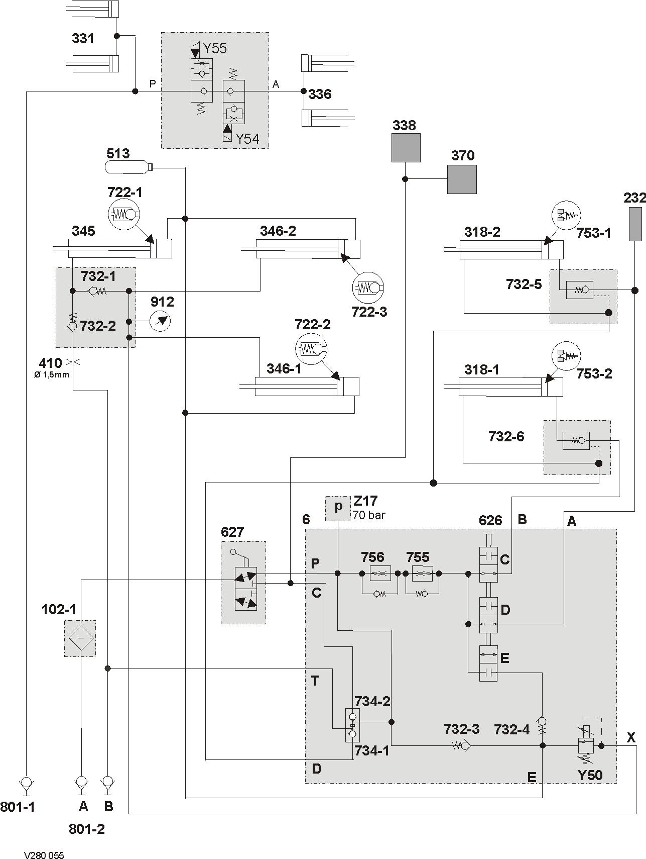
2.4 Function ñ with active hydraulic system, main valve block 039 866.0 from serial no. 7300 3039 (V280), 7320 1875 (V260)
Description of function:
Closing the tailgate - without active hydraulic system Oil enters the valve block (6, port T) via port (801-2 B) and opens the lock-up valve unit non-return valve (734-1). Via port D, the pressurized oil flows to the non-return valves (732-5 and 732-6) which are unlocked. The pressurized oil flows on into the rod spaces of hydraulic cylinders (318-1 and 318-2). The tailgate is closed. The oil displaced from the ram spaces of hydraulic cylinders (318-1 and 318-2) flows via the unblocked non-return valves (732-5 and 732-6), the shut-off taps (626 C and 626 D), the flow controllers (755 and 756), the shut-off tap (627) and filter (102-1) into the tank. The flow controllers (755 and 756) regulate the oil flow to 18 l/min. which reduces the closing time of the tailgate as compared with the opening time.
Closing the tailgate - with active hydraulic system 1. The pilot-controlled non-return valves (732-5 and 732-6) reliably seal off the tailgate cylinders. This is particularly important when performing service work while the tailgate is open. The tailgate can be closed only by building up pressure in port (801-2 B).
2. Via port (801-2 B), oil also flows into the rod spaces of hydraulic cylinders (345, 346-1 and 346-2) in order to retract the hydraulic cylinders quickly ñ the belts are tensioned. To this end, the non-return valves (732-1 and 732-2) are opened by the oil flow.
The oil is applied at port X of the Baling pressure build-up solenoid valve (Y55) which is electronically regulated to 90 bar during the tailgate closing process.
The oil displaced from the ram spaces of hydraulic cylinders (345, 346-1 and 346-2) is drained via the non-return valve (732-3), the shutoff tap (627) and port A.
Baling Baled material pulls the hydraulic cylinders (346-1, 346-2 and 345) to the outside by means of the tensioning arms. Baling pressure is thus built up in the rod spaces of these cylinders; this pressure can be read at pressure gauge (912). The baling pressure enters valve block (6) at inlet (X) and is applied to the Baling pressure build-up valve (Y50). When the set baling pressure has been reached, the baling pressure build-up solenoid valve (Y50) opens, making oil flow via port (E) into the ram sides of hydraulic cylinders (346-1, 346-2 and 345). The hydraulic accumulator (513) compensates the volumetric difference between the cylinder sides.
Opening the tailgate - without active hydraulic system Oil flows into valve block 6 (port P) via port (801-2 A), filter (102-1) and the rotor clutch / 2nd belt drive shut-off tap (627). Oil flows via the open shut-off taps (626C and 626D) into the ram spaces of hydraulic cylinders (318-1 and 318-2), via ports (A and B) and the nonreturn valves (732-5 and 732-6). During this process, the flow rate is regulated to 50 l/min. by the flow controllers (756 and 755). At the same time, the lubricating oil pump (232) is supplied. Pressurized oil is tapped directly downstream of inlet (P) of valve block (6) which opens the lock-up valve unit non-return valve (734-1) via a ram. The oil displaced from the rod spaces of hydraulic cylinders (318-1 and 318-2) flows through the open lock-up valve unit non-return valve (734-1) and port (T) to the quick release coupling (801-2 B). Downstream of the rotor clutch / 2nd belt drive shut-off tap (627), pressurized oil flows to the rotor cut-out clutch (338) and to the drive clutch (370) for roller 3. The clutches open so that the rotor and the drive of roller 3 are switched off while the tailgate is opened.
Opening the tailgate - with active hydraulic system As early as when opening the tailgate, the pressure rises to above 70 bar. The pressure switch (Z17) opens. With this signal, the module regulates the Baling pressure build-up solenoid valve (Y50) to 0 bar. Now the rod spaces of hydraulic cylinders (345, 346-1 and 346-2) are pressureless and the belts are relieved ñ opening the tailgate is accelerated.
Relieving the belts (for maintenance work in the baling chamber) 1. Switch on control box (baler CCT) so the Baling pressure build-up solenoid valve (Y50) is energized.
2. Disengage the p.t.o. shaft.
3. Open the tailgate as far as necessary and secure it.
4. Actuate the shut-off valve (626):
The shut-off taps (626 C) and (626 D) of the tailgate are now blocked and shut-off tap (626 E) is open. Oil flows into valve block 6 (port P) via port (801-2 A), filter (102-1) and shut-off tap (627). Oil continues to flow via filter (102-2), non-return valve (732-4) and port (E) into the ram spaces of hydraulic cylinders (346-1, 346-2 and 345) through the open shut-off tap (626 E). The cylinders extend and the belts are relieved. The oil displaced from the rod spaces of hydraulic cylinders (346-1, 346-2 and 345) flows to the Baling pressure build-up solenoid valve (Y50) via port (X). This valve is electronically regulated to 0 bar when the tailgate is open and oil may therefore flow freely through it. The rod spaces and the ram spaces of the belt tensioner cylinders (346-1, 346-2 and 345) are now connected with each other. There is the same pressure in both cylinder spaces, but since the greater force is generated on the ram surface, the cylinders extend and relieve the belts.
Tensioning the belts The baling chamber service shut-off valve still is in the "Tailgate blocked" position; now the double-acting control unit provided on the tractor is set to the "Lower" position. The hydraulic cylinders (346-1, 346-2 and 345) are retracted by springs on the left baler side. When maintenance work is complete, the tailgate is closed and the belts must be driven during closing. Otherwise there is a risk of the belts being squeezed.
- with active hydraulic system The oil displaced from the ram spaces during this process flows into the tank via non-return valve (732-3), shut-off tap (627) and port (801-2 A). The pressure relief valve (754) is mechanically blocked = no function.
Swinging in the knife support
Swinging out the knife support When actuating the "Swing in knife support" button, the 2/3 way directional control valve (Y55) "ROTOCUT knives IN" is energized. Oil flows into the ROTOCUT knives hydraulic cylinders (336) via port (801-1) and the energized 2/3 wayvalve. The ROTOCUT knives hydraulic cylinders (336) extend and swing in the knife support. The extended ROTOCUT knives hydraulic cylinders (336) are kept in their position by the non-return valve inside the 2/3 directional control valve (Y54).
The single-acting tractor control unit is set to the "Lower" position ñ port (801-1) is connected to the tank. When actuating the "Swing out knife support" button, the 2/3 way directional control valve (Y54) is energized. The baled material loads the ROTOCUT knives hydraulic cylinders (336), making oil flow into the tank from the ram spaces via the energized 2/3 way valve (Y54), the unenergized 2/3 way valve (Y55) and port (801-1).