1 minute read
ADJUSTING THE PRELOAD OF THE DRIVE PINION BEARINGS
– Fit the drive gear (5) into the casing. – Fit the bearing plate (9) with a shim (8) of 0,25 mm to create an axial gap (J) for the drive pinion. – Tighten the screws (10) to 9,5±0,5 daN·m.
Note: The value is given for information.
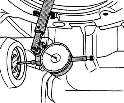
– By opening the RH hydraulic cover, pull the pinion, turning it alternately clockwise and anticlockwise in order to properly seat the cones in the cups. – Position a dial gauge at the end of the pinion. – Set the comparator to zero and measure the gap (J). – According to the value measured, select the thickness of the shims "E1"(8) to remove any play and apply a preload "P1" of 0,06 +/- 0,03 mm. E1=0,25–J–P1. – Check that the drag torque ranges from 0,5 to 2,5 daN·m. – Place the selected thickness of shims "E1" and refit the thrust plate (9) (3 shims maximum). – Fit and tighten the screws (10), coated with Loctite (271), to 9,5 ± 0,5 daN·m.
8
9
J
5
10
343msm1g Fig. 23
343msm47 Fig. 24


