9 minute read
Front Cover, Timing Chain, and Crankshaft Balancer
Removal and Installation
3 7
4 8
2 1 5 9 6
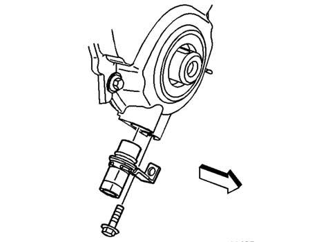
Removal steps
1. Cover 2. Seal 3. Bolt 4. Sprocket 5. Chain 6. Drive Gear 7. Bolt 8. Gear 9. Sprocket
1. Remove the crankshaft balancer. 2. Remove the water pump. 3. Remove the crankshaft position sensor bolt. 4. Remove the crankshaft position sensor.
5. Remove the crankshaft position sensor seal (O-ring). 6. Discard the crankshaft position sensor seal (O-ring).
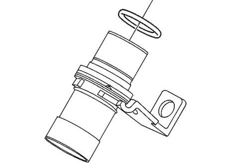
7. Remove the engine front cover bolts. 8. Remove the engine front cover. 9. Discard the engine front cover.
NOTE
Do not reuse the engine front cover. Always install a new engine front cover. 1. Disconnect the negative battery cable. 2. Remove the crankshaft balancer. 3. Remove the crankshaft front seal.
Timing Chain and Sprockets Removal
Tools Required
•J 23523-F Crankshaft Balancer
Remover and Installer •J 5825-A Crankshaft Sprocket Puller
NOTE
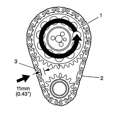
Check the camshaft timing chain free play. Replace the camshaft timing chain if it can be moved back and forth in excess of 16 mm (0.625 in.).
1. Remove the engine front cover. 2. Check the camshaft timing chain free play. 2.1.Rotate the camshaft sprocket (1) counterclockwise until all slack is removed from the camshaft timing chain (2). 2.2.Measure the free play on the slack side (3) of the camshaft timing chain. If the camshaft timing chain can be moved side to side in excess of 11 mm (0.43 in), replacement of the camshaft timing chain and the sprockets is recommended during assembly.
480542
3. Remove the crankshaft position sensor reluctor ring. 6. Remove the crankshaft sprocket using the crankshaft sprocket puller J 5825-A.
J 5825 - A
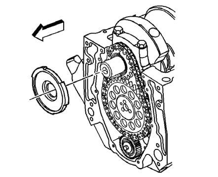
4. Remove the camshaft sprocket bolts.

480541
7. Remove the camshaft balancer key.
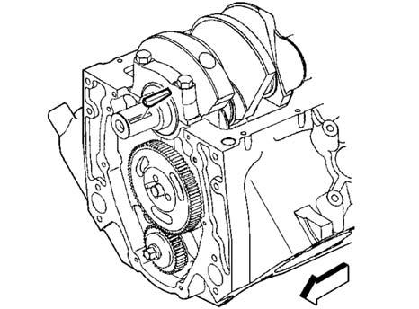
480544
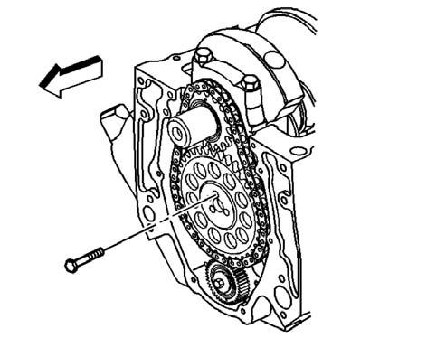
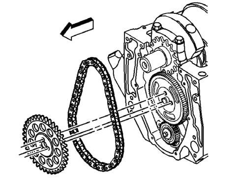
5. Remove the camshaft sprocket and the camshaft timing chain.
480546
! CAUTION
Safety Glasses must be worn or eye injury may occur.
387761
Timing Chain and Sprockets Clean and Inspect
! CAUTION
Refer to Safety Glasses Caution in Cautions and Notices.
1.Clean the components with cleaning solvent. 2.Dry the components with compressed air. 3. Inspect the camshaft timing chain for binding or wear.
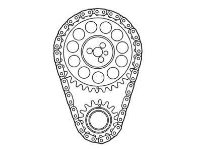
4. Inspect the camshaft sprocket and the crankshaft sprocket for the following: • Broken teeth (1) • Damaged teeth (2) • Chipped teeth (3) • Worn teeth • Uneven wear on the edge of the teeth • Worn valleys between the sprocket teeth • Crankshaft sprocket keyway for wear

Crankshaft Balancer Removal
Tools Required
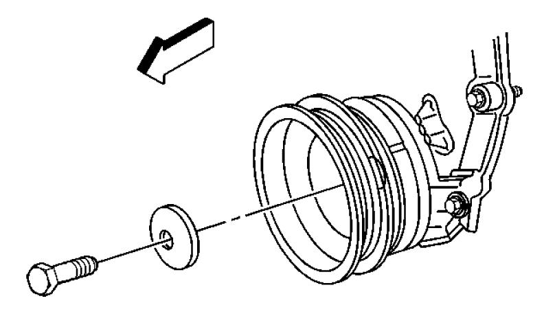
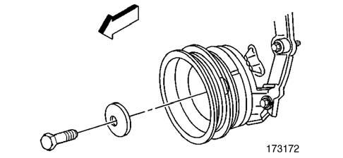
• J 23523-F Balancer Remover and Installer 1. Remove the crankshaft balancer bolt and washer.
173172
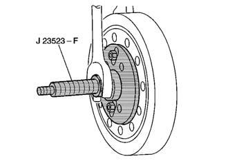
2. Remove the bolts and the crankshaft pulley. 3. Use the balancer remover and installer J23523-F in order to remove the crankshaft balancer. a.Install the balancer remover and installer J23523-F plate and bolts onto the crankshaft balancer and tighten.
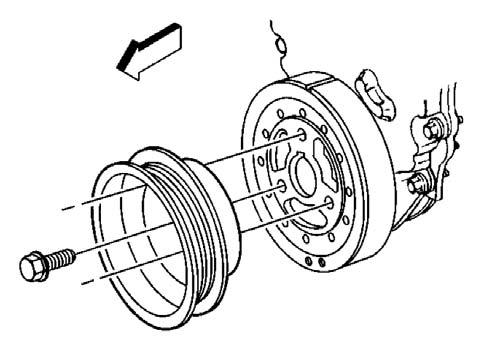
Tightening torque for Balancer bolts 2.49 Kgf•m (18 lb ft) [25 N•m]
b.Install the balancer remover and installer J23523-Fforcing screw into the plate. c.Rotate the balancer remover and installer J23523-Fforcing screw clockwise in order to remove the crankshaft balancer. 4. Remove the balancer remover and installer
J23523-Ffrom the crankshaft balancer.
J 23523-F
4059
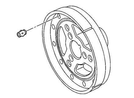
Important: If replacing the crankshaft balancer, NEW weights must be installed into the NEW crankshaft balancer, in the same location as the old weights in the old balancer. 5. Note the position and length of any crankshaft balancer front groove pins, if applicable.
334258
Tools Required
•J 23523-F Crankshaft Balancer Remover and
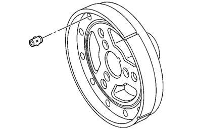
Installer 1. Look to ensure that the front groove pin (crankshaft balancer) is installed in the proper location (if applicable).
334258
Important: The inertial weight section of the crankshaft balancer is assembled to the hub with a rubber type material. The correct installation procedures (with the proper tool) must be followed or movement of the inertial weight section of the hub will destroy the tuning of the crankshaft balancer. 2. Apply a small amount of adhesive A000000165,
GM P/N 12346141 or equivalent onto the crankshaft balancer keyway in order to seal the crankshaft balancer keyway and crankshaft joint. 3. Align the keyway of the crankshaft balancer with the crankshaft balancer key. 4. Install the crankshaft balancer onto the end of the crankshaft.
b.Install the J 23523-F screw into the end for the crankshaft. c.Install the J 23523-F bearing, thewasher and the nut onto the J 23523-F screw. d.Rotate the J 23523-F nut clockwise until the crankshaft balancer hub iscompletely seated against the crankshaft position sensor reluctor ring. 6. Remove the J 23523-F.
J 23523–F
7. Install the crankshaft pulley and bolts.
4065
Tightening torque for Crankshaft pulley bolts 5.94 Kgf•m (43 lb ft) [58 N•m]
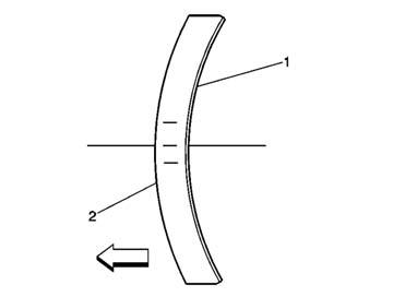
8. Ensure that the crown of the crankshaft balancer washer (2) is faced away from the engine.
1
188059
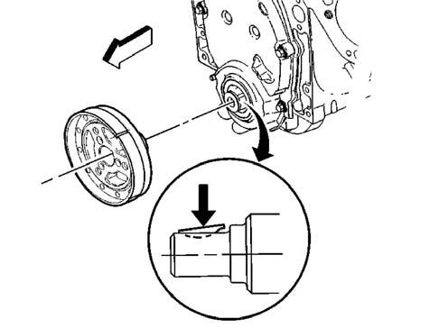
5. Use the J 23523-F in order to press the crankshaft balancer onto the crankshaft. a.Install the J 23523-F plate and bolts onto the front of the crankshaft balancer and tighten to the specified torque.
Tightening torque for Balancer bolts 2.49 Kgf•m (18 lb ft) [25 N•m]
2
342203
9. Install the crankshaft balancer washer and the bolt, tighten to the specified torque.
Tightening torque for Crankshaft 9.67 Kgf•m (70 lb•ft) [95N•m]
Balancer bolt
Tools Required
•J 5590 Crankshaft Sprocket Installer 1.Install the key into the crankshaft keyway.
The crankshaft balancer key should be parallel to the crankshaft or with a slight incline.
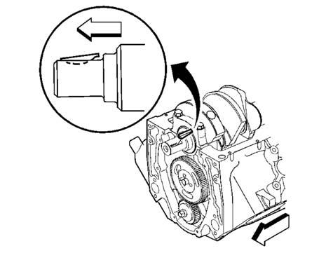
387766
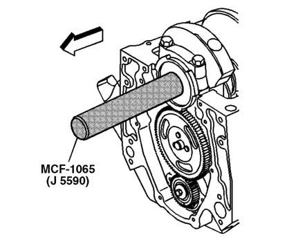
2. Align the keyway of the crankshaft sprocket with the crankshaft balancer key. 3. Use the crankshaft sprocket installer J 5590 to install the crankshaft sprocket.
J 5590
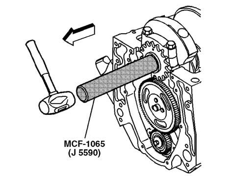
480574 4. Rotate the crankshaft until the crankshaft sprocket is at the 12 o’clock position. Important: Install the crankshaft sprocket with the alignment mark at the 6 o’clock position. 5. Install the crankshaft sprocket and the camshaft timing chain.
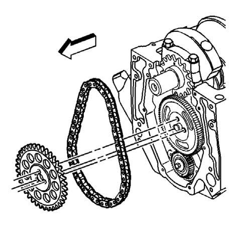
480546
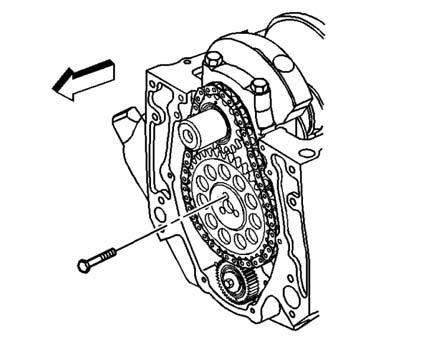
6. Look to ensure that the crankshaft sprocket is aligned at the 12 o’clock position and the camshaft sprocket is aligned at the 6 o’clock position.
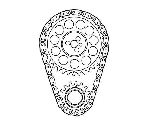
480575
Important: Do not use a hammer to install the camshaft sprocket onto the camshaft. To do so may dislodge the expansion cup plug (camshaft rear bearing hole). 7. Install the camshaft sprocket bolts.
Tightening torque for camshaft 2.49 Kgf•m (18 lb•ft) [25N•m] sprocket bolts
480544
8.Install the crankshaft position sensor reluctor ring. a. Align the keyway on the crankshaft position sensor reluctor ring with the crankshaft balancer key in the crankshaft. b. Use the crankshaft sprocket installer J 5590 to push the crankshaft position sensor reluctor ring onto the crankshaft until completely seated against the crankshaft sprocket.
Tools Required
•J 35468 Crankshaft Seal Installer and
Centering Tool 1.Install the crankshaft front seal. 2.Install the crankshaft balancer.
Engine Front Cover Installation
NOTE
Once the composite engine front cover is removed DONOT reinstall the engine front cover. Always install a new engine front cover.
Tightening torque for front cover 1.22 Kgf•m (106 lb•in) [12 N•m] bolts
1.Install the NEW engine front cover. 2.Install the front cover bolts.
J 5590
480574 4068
Important: Do not reuse the original crankshaft position sensor seal (o-ring). When installing the crankshaft position sensor, be sure the crankshaft position sensor is fully seated and held stationary in the engine front cover crankshaft position sensor bore. A crankshaft position sensor that is not completely seated will cock in the engine front cover and may result in erratic engine operation. 3. Lubricate the NEW crankshaft position sensor seal (o-ring) with clean engine oil. 4. Install the NEW crankshaft position sensor seal (o-ring) onto the crankshaft position sensor.
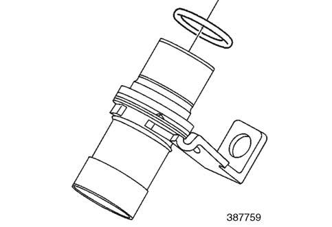
5. Install the crankshaft position sensor until fully seated into the engine front cover. 6. Install the crankshaft position sensor bolt.
Tightening torque for crankshaft position bolt .82 Kgf•m (71 lb ft) [8 N•m]
Tools Required
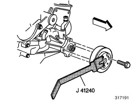
•J 41240 Fan Clutch Remover and Installer 1.Remove the bolts and the fan and water pump pulley using the J 41240.
2.Remove the clamps and water pump inlet hose.
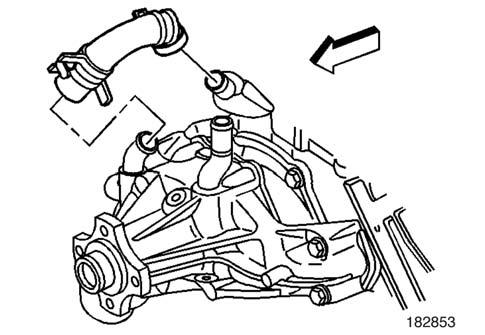
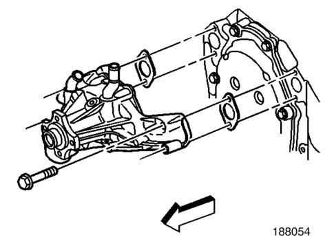
3.Remove the water pump bolts. 4.Remove the water pump. 5.Remove the water pump gaskets. 6.Discard the water pump gaskets.
! CAUTION
Refer to Safety Glasses Caution in Cautions and Notices.
1.Remove all the old gasket material from the water pump sealing surfaces. 2.Clean all the dirt and any debris from the water pump. 3.Inspect the water pump for the following: •Leakage or damage to the housing cover or gasket (1) •Excessive scratches or grouping to the gasket sealing surfaces (2) •Leakage from the water pump vent hole (3)
A stain around the vent hole is acceptable. If leakage occurred (dripping) with the engine operating and the cooling system pressurized, then replace the water pump. •Damaged bolt hole threads (4) •Excessive side-to-side movement of the water pump shaft (5) •Leakage around the water inlet pipe (6) •Leakage around the heater hose pipe (7) •Restrictions within the internal coolant passages
Tools Required
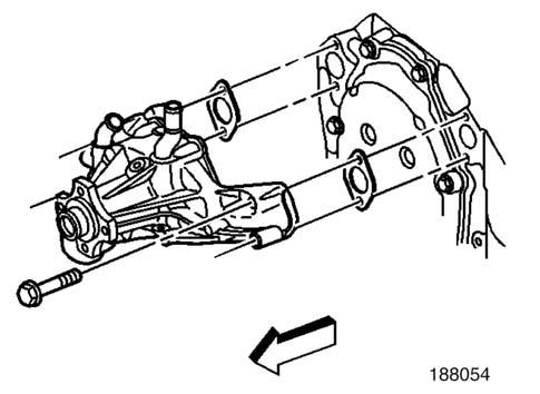
•J 41240 Fan Clutch Remover and Installer 1.If reusing the fasteners, apply sealant GM P/N 12346004 or equivalent to the threads of the water pump bolts. 2.Install the water pump and the NEW water pump gaskets. 3.Install the water pump bolts.

Important: After final assembly, the water pump inlet hose clamp tangs (water pump end) must point forward and the upper tang should be level with the outside diameter of the water pump inlet hose. 4.Install the water pump inlet hose and the water pump inlet hose clamps.
Tightening torque for water pump bolts 4.56 Kgf•m (33 lb ft) [45 N•m]

5.Install the fan and water pump pulley and bolts using the J 41240.
Tightening torque for water pump pulley bolts 2.497 Kgf•m (18 lb ft) [25 N•m]


