
9 minute read
Piston and Connecting Rod
Removal and Installation
Removal steps
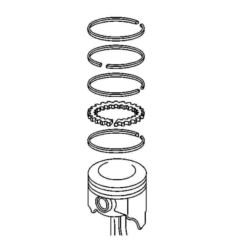
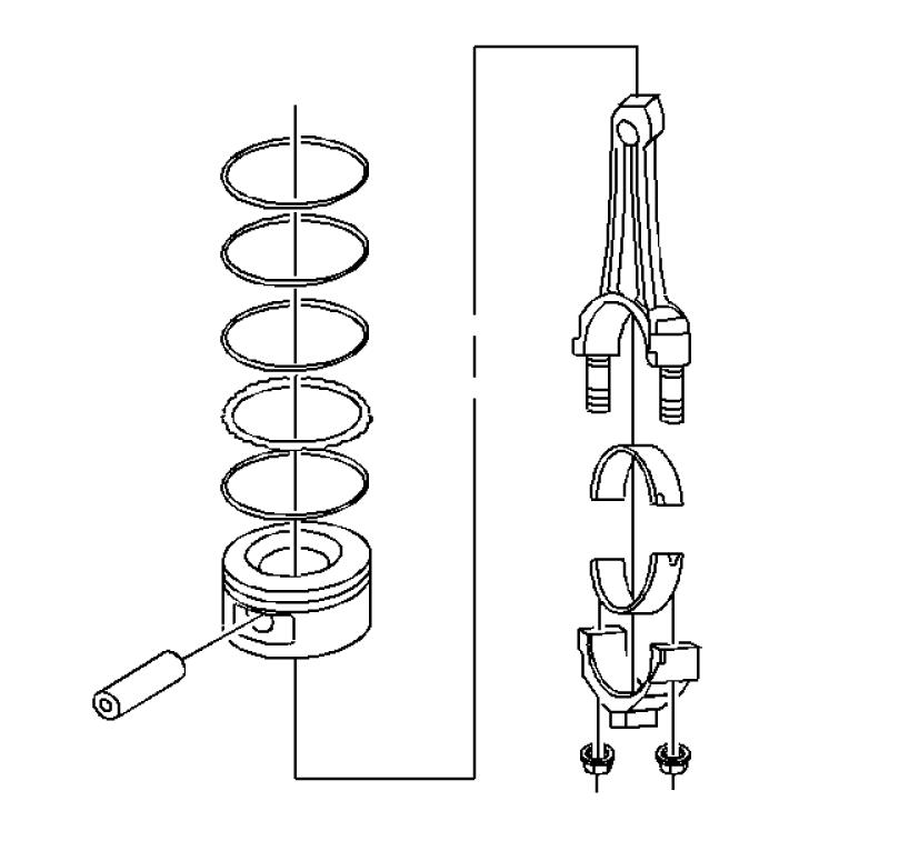
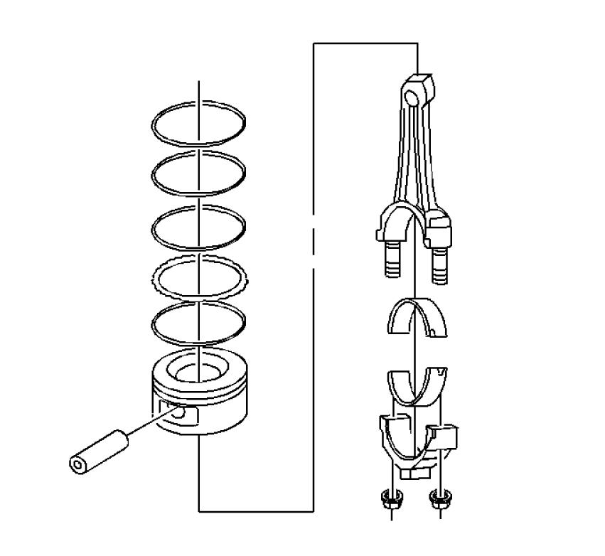
1. Nut 2. Rod Cap 3. Bearing 4. Bearing 5. Piston and Connecting Rod Assy 6. Pin 7. Rod - Connecting 8. Piston 9. Ring Kit
Piston, Connecting Rod, and Bearing Removal
Tools Required
• J 24270 Cylinder Bore Ridge Reamer • J 5239 Guide Set 1.Use the cylinder boer ridge reamer J 24270 to remove the cylinder ring ridge. a.Turn the crankshaft until the piston is at the bottom of the stroke. b.Place a cloth on top of the piston. c.Use a ridge reamer to remove cylinder ring ridge. d.Turn the crankshaft so the piston is at the top of the stroke. e.Remove the cloth. f.Remove the cutting debris. Important: Place matchmarks or numbers on the connecting rods and the connecting rod caps. Assemble the connecting rod caps to the matching connecting rods. 2.Remove the connecting rod nuts. 3.Remove the connecting rod cap. 4.Remove the connecting rod bearings. • Keep the bearings with the original connecting rod and connecting rod cap. • Wipe the oil from the bearings. • Wipe the oil from the crankpins.
11497 480549
5.Use the guide set J 5239 to protect the crankshaft vournals and to remove the connecting rod and the piston out of the top of the engine block.
31373
Tools Required
• J 24086 Piston Pin Remover/Installer
NOTE
Important: Mark the piston for installation to the proper cylinder.
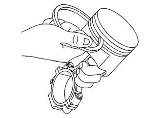
1.Remove the piston rings from the pistons.
4967
2.Press the piston pin from the connecting rod using the piston pin remover/installer J 24086-C. 3.The piston pin has an interference fit into the connecting rod, and is full floating in the piston.
J 24086-C
4965 4.Mark, separate and organize the parts for assembly.
34671
Piston, Connecting Rod and Bearings Clean and Inspect
Important: Measurement of all components should be taken with the components at room temperature. Do not use a wire brush in order to clean any part of the piston.
! CAUTION
Safety Glasses must be worn or eye injury may occur. 1. Clean the piston and connecting rod in solvent. 2. Dry the components with compressed air.
34671
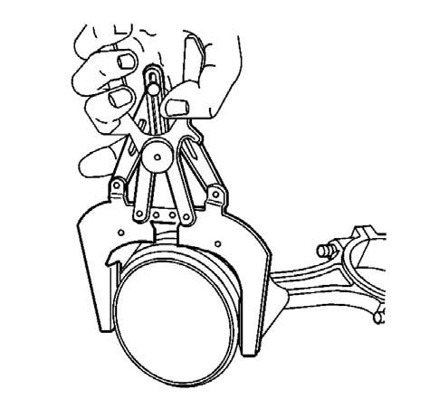
3. Clean the piston ring grooves with a suitable ring groove cleaning tool.
4977
4.Clean the piston oil lubrication holes and slots. 5.Inspect the piston for the following: • Eroded areas (1) on the top of the piston • Scuffed or damaged skirt (2) • Damage to the pin bore (3) • Cracks in the piston ring lands, the piston skirt or the pin bosses • Piston ring grooves for nicks, burrs or other warpage which may cause the piston ring to bind
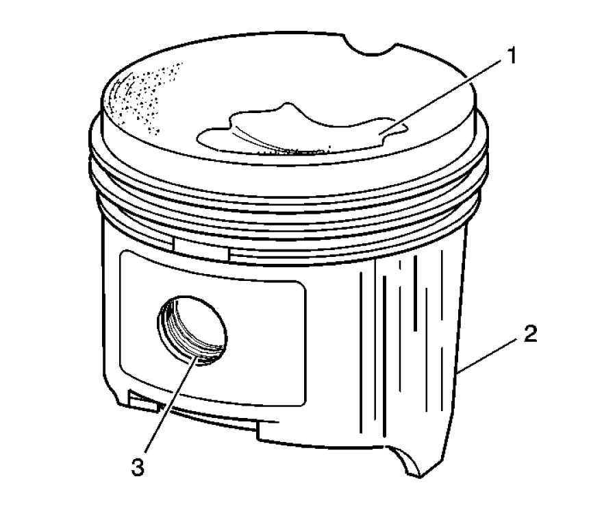
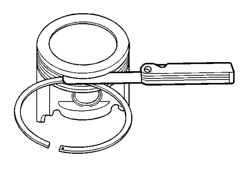
156168 6.Inspect the piston pin for scoring, wear or other damage. 7.Measure the piston ring-to-piston ring groove side clearance. a.Insert the edge of the piston ring into the piston ring groove. b. Roll the piston ring completely around the piston. ■ If binding is caused by a distorted piston ring groove, MINOR imperfections may be removed with a fine file. ■ If binding is caused by a distorted piston ring, replace the piston ring.

4969
8. Measure the piston ring side clearance with a feeler gauge. 9. If the side clearance is too small, try another piston ring set. 10.If the proper piston ring-to-piston ring groove clearance cannot be achieved, replace the pistonand pin assembly. 11. To determine the proper piston ring side clearance, refer to General Specifications.
22934
12.To determine piston pin-to-bore clearance, use a micrometer and measure the piston pin.

4976
13.To determine piston pin-to-bore clearance, use an inside micrometer and measure the piston pin bore. 14.To determine the piston pin-to-bore clearance, subtract the piston pin diameter from the piston pin bore diameter. Refer to General
Specifications.

4975
15.Measure the piston with a micrometer at a right angle to the piston pin bore, measure the piston at 11 mm (0.433 in) from the bottom of the skirt. Refer to General Specifications. If the piston is not within specifications, replace the piston and pin as an assembly.
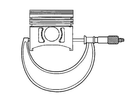
188016
16.Inspect the connecting rod for an out-of-round bearing bore. Refer to General Specifications.
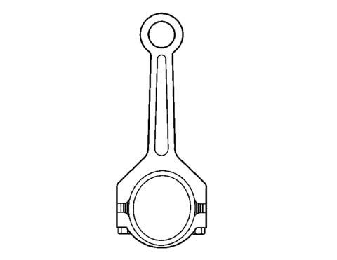
156167
17.Inspect the connecting rod for twisting. 18.Inspect the connecting rod for damage to the bearing cap and bolt threads.

156169
19.Measure the piston compression ring end gap. Important: Fit each compression ring to the cylinder in which it will be used. 20.Place the compression ring into the cylinder bore. a.Push the compression ring into the cylinder bore to approximately 6.5 mm (0.25 in) above the ring travel. The ring must be square to the cylinder wall. b.Use a feeler gauge in order to measure the end gap. c.Select another size ring set if the end gap exceeds specifications. Refer to General Specifications.
Piston Selection
Tools Required
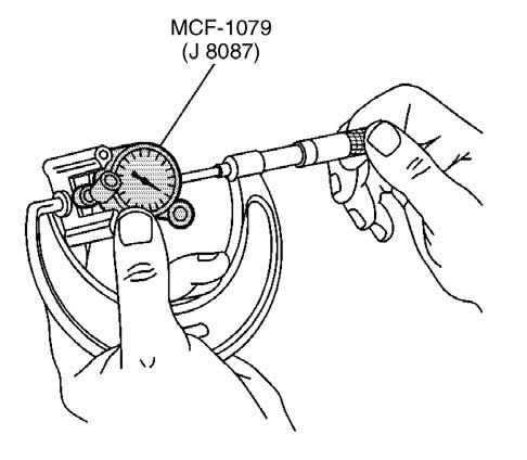
• J 8087 Cylinder Bore Gauge Important: Measurements of all components should be taken with the components at normal room temperature. For proper piston fit, the engine block cylinder bores should not have excessive wear or taper. A used piston and piston pin set may be reinstalled if, after cleaning and inspection, the piston and piston pin are within specifications. 1. Use the cylinder bore guage J 8087 to measure the cylinder bore diameter. Measure at a point 64 mm (2.5 in) from the top of the cylinder bore and 90 degrees to the crankshaft centerline.
J 8087
4972 2.Measure the cylinder bore guage J 8087 with a micrometer and record the reading.

J 8087
4974
3.With a micrometer or caliper at a right angle to the piston pin bore, measure the piston 11 mm (0.433 in) from the bottom of the skirt. 4.Subtract the piston diameter from the cylinder bore diameter in order to determine piston-tobore clearance. Refer to General Specifications. 5.If the proper clearance cannot be obtained, then select another piston and measure the clearances.
If the proper fit cannot be obtained, the cylinder bore may require honing or boring. 6.When the piston-to-cylinder bore clearance is within specifications, permanently mark the top of the piston for installation into the proper cylinder.

188016
Piston, Connecting Rod and Bearing Installation
Tools Required
•J 5239 Guide Set •J 8037 Piston Ring Compressor •J 36660 Torque Angle Meter 1.Coat the following components with clean engine oil: • The piston • The piston rings • The cylinder bore • The bearing surfaces 2.Install the guide set J 5239 onto the connecting rod bolts.
J 5239

387765
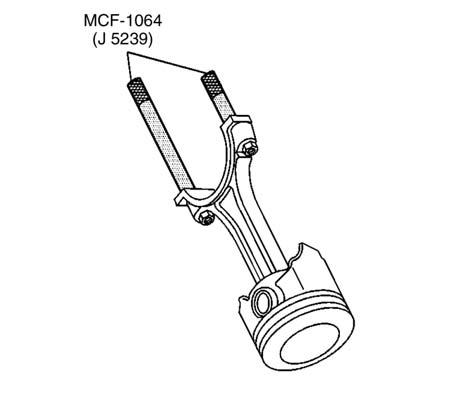
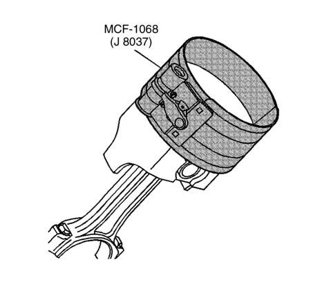
3.Install the piston ring compressor J 8037 onto the piston andcompress the piston rings.
J 8037
Important: The mark on top of the piston must face the front of the engine block. When assembled, the flanges on the connecting rod and connecting rod cap should face the front of the engine block on the left bank, and to the rear of the engine block on the right bank. 4.Install the piston and connecting rod assembly, and the piston ring compressor J 8037 into the proper cylinderbore.
J 8037
492144
5.Use the piston ring compressor J 8037 and the guide set J 5239 to lightly tap the top of the piston with a wooden hammer handle. a.Hold the piston ring compressor J 8037 firmly against the engine block until all of the piston rings enter
J 8037
480573 5159
b.Use the guide set J 5239 to guide the connecting rod onto the crankshaft journal. 6.Remove the piston ring compressor J 5239.
J 5239
8.After the piston and connecting rod assemblies have been installed, then lightly tap each connecting rod assembly (parallel to the crankpin) in order to insure that the connecting rods have side clearance.
31373
7.Install the connecting rod cap, bearings and nuts.
Tightening torque 1st pass for rod cap nuts 2.77 Kgf•m (20 lbf•ft) [27 N•m]
• On the final pass, use the electronic torque angle meter J 36660to tighten the nuts an additional 70degrees.
Tightening torque Final pass for rod cap nuts Additional 70°

480545 5163
9.Use a feeler gauge or a dial indicator to measure the connecting rod side clearance between the connecting rod caps. The connecting rod side clearance should be 0.16-0.44mm (0.006-0.017 in.).
Piston and Connecting Rod Assemble
Tools Required
• J 24086-C Piston Pin Remover/Installer
! CAUTION
Avoid contact with HOT components. Wear safety glasses and protective gloves to avoid personnel injury.
NOTE
Important: Applying excessive heat to the connectingrod may damage or distort the rod. Rod temperature SHOULD NOT exceed 315°C (600°F). At this temperature, the end of the connecting rod will turn a straw color upon visual inspection.
NOTE
Important: After the MCF-1083 (J 24086-C) installer hub bottoms on the support assembly, DO NOT exceed 35,000 kPa (5,000 psi) or the tool may be damaged.
Important: When assembling the piston and connecting rod, the mark on the top of the piston must point to the front of the engine block. The left bank connecting rods should have the flange face toward the front of the engine block. The right bank connecting rods should have the flange face toward the rear of the engine block. The piston pin has an interference fit into the connecting rod and is full floating in the piston.
1.Install the piston pin and connecting rod assembly. a.Lubricate the piston holes in both the piston and the connecting rod assembly with clean engine oil. b.Use a torch and apply MILD heat to the piston pin end of the connecting rod. c.Press the piston pin into the piston and connecting rod assembly using the piston pin remover/installer J 24086-C. d.Inspect for proper installation of the piston and piston pin. The piston must move freely on the piston pin with no binding or interference.
J 24086-C
NOTE
4965
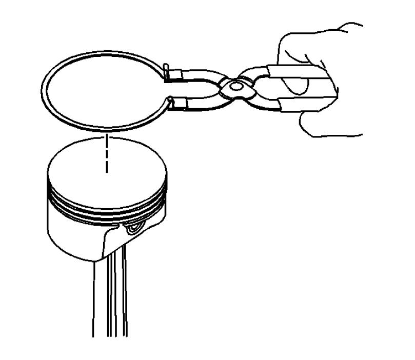
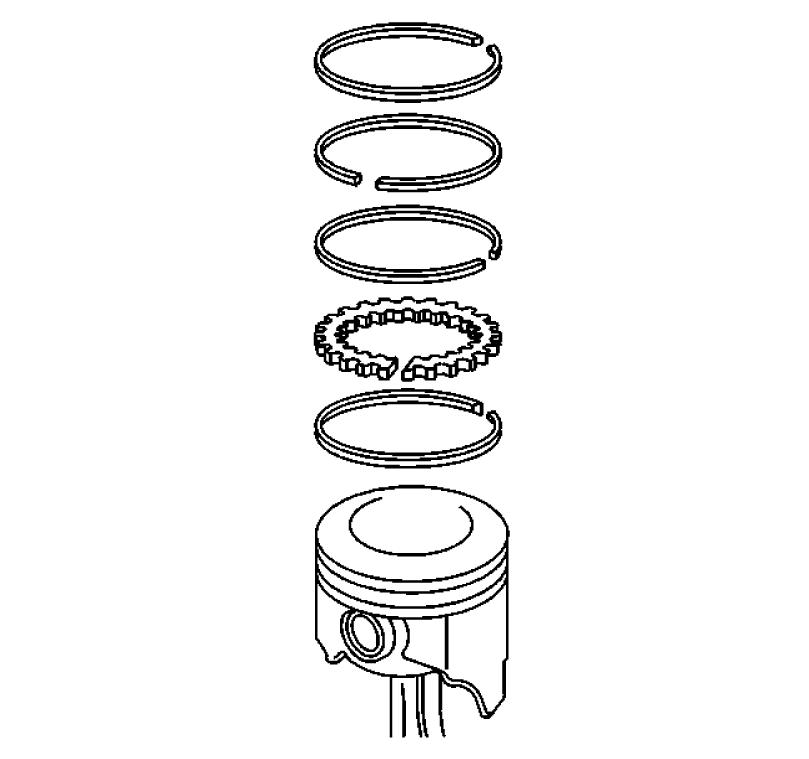
Important: Use a piston ring expander to install the piston rings. The rings may be damaged if expandedmore than necessary. 2.Install the piston rings onto the piston. a.Install the oil control piston ring spacer. b.Install the lower oil control piston ring. c.Install the upper oil control piston ring. d.Install the lower compression piston ring. The mark on the side of the piston ring should face the top of the piston. e.Install the upper compression piston ring. The mark on the side of the piston ring should face the top of the piston.
490763
3.Space the compression piston ring end gaps 120 degrees apart. 4.Space the oil control piston ring end gaps a minimum of 90 degrees apart.
-126-


