
11 minute read
Cylinder Block
Cleaning and Inspection
Disassembly steps
1. Engine support (R.H.) 2. Engine support (L.H.) 3. Cylinder block
7EN0035
Tools Required
• J 41712 Oil Pressure Switch Socket 1.Remove the knock sensor from the engine block.
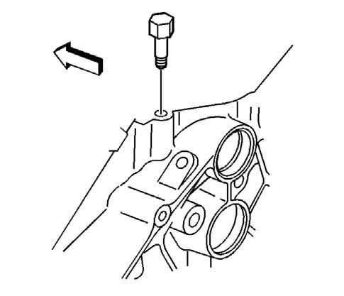
10793
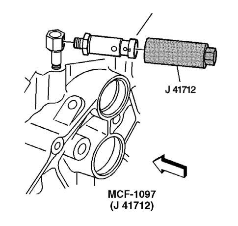
2.Remove the engine oil pressure gauge sensor using the oil pressure switch socket J41712.
188020
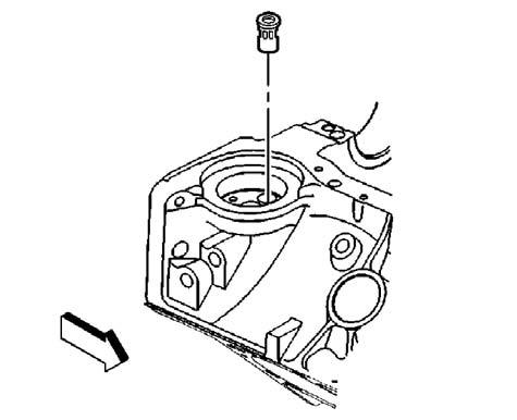
4.Remove the dowel straight pins (transmission locator) (if required).
J 41712
188018 334350
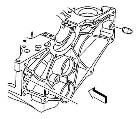
5.Remove the engine block left side oil gallery plug. 6.Remove the engine block left rear oil gallery plug. 7.Remove the engine block right rear oil gallery plug.
5271
8.Remove the expansion cup plug (camshaft rear bearing hole) and discard.
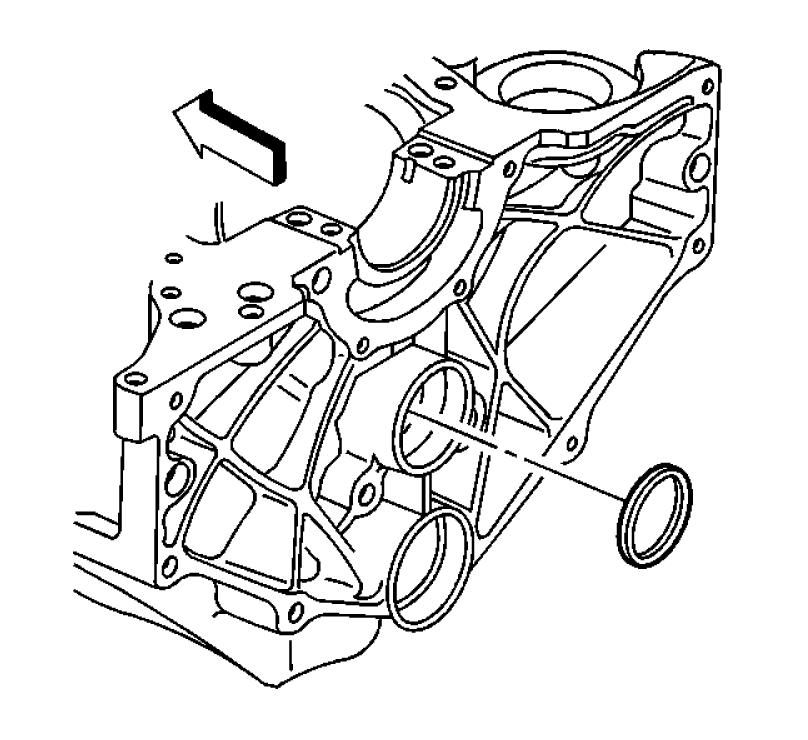
334364
9.Remove the expansion cup plug (balance shaft rear bearing hole) and discard.
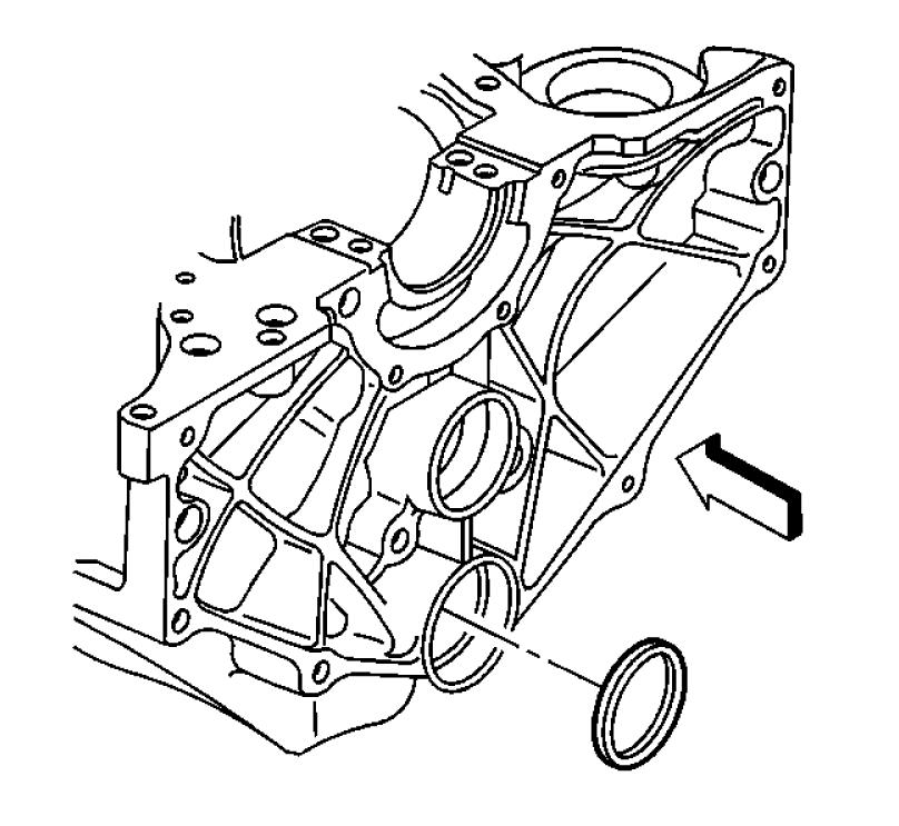
334366 10.Remove the spring type S pin (crankshaft rear oil seal housing locator) (if required).
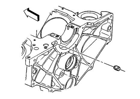
334323
11.Remove the front oil gallery plugs or balls from the front of the engine block and discard. 12.Insert a 3/8 x 26 in. rod into the rear oil gallery holes in order to drive out the front oil gallery plugs or balls.
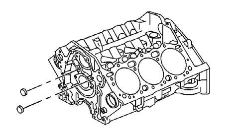
5270
13.Remove the engine block core hole plugs. a.Use a suitable tool in order to drive the engine block core hole plugs into the coolant jacket. b.Use a suitable tool in order to pull the engine block core hole plugs from the coolant jacket. c.Discard the engine block core hole plugs.
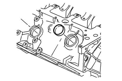
480550
188026
Engine Block Clean and Inspect
Tools Required
• J 8087 Cylinder Bore Gauge
! CAUTION
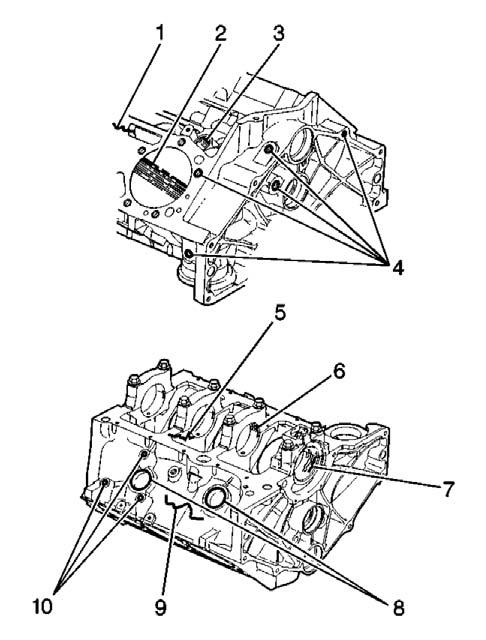
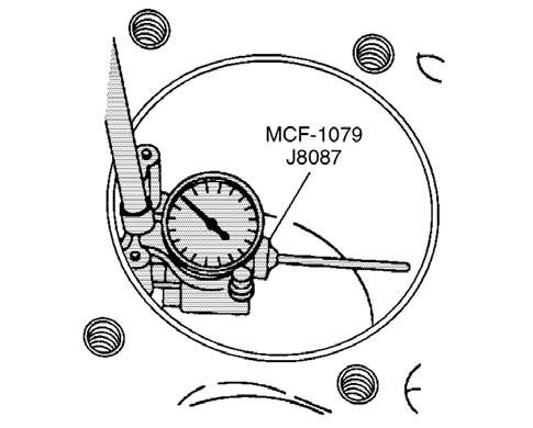
334378 1.Clean all the remaining sealing or gasket material from the sealing surfaces. 2.Clean the engine block with cleaning solvent. 3.Flush the engine block with clean water or steam. 4.Clean the cylinder bores. 5.Clean the oil galleries and the oil passages. 6.Clean the scale and the deposits from the coolant passages. Notice: Clean all debris, dirt and coolant from the engine block cylinder head bolt holes. Failure to remove all foreign material may result in damaged threads, improperly tightened fasteners or damage to the components. 7.Clean the engine block cylinder head bolt holes. 8.After cleaning the engine block, spray or wipe the cylinder bores and the machined surfaces with clean engine oil. 9.Inspect the following areas: • Coolant jackets (1) for cracks • Cylinder bores (2) for scratches or gouging • Valve lifter bores (3) for excessive scoring or wear • Threaded holes (4) for damage • Crankshaft bearing webs (5) for cracks • Crankshaft bearing caps (6) and the crankshaft bearing bores (7) for damage ■ The crankshaft bearing bores should be round and uniform when measuring the inside diameter (ID). ■ The surface where the crankshaft bearings contact the crankshaft bearing bore should be smooth. ■ If a crankshaft bearing cap is damaged and requires replacement, replace the crankshaft bearing cap first, then rebore the engine block crankshaft bearing bores and check for proper alignment. Finally, check the crankshaft for the proper clearances. • Engine block core hole plug bores (8) for damage • Engine block (9) for cracks or damage • Engine mount bosses (10) for damage 10.Measure the cylinder bores for taper and out-ofround. a.Depress the plunger on the cylinder bore guage J 8087 7 mm (0.275 in) or until the J 8087 enters the cylinder bore. b.Center the cylinder bore guage J 8087in the cylinder bore and turn the indicator dial to 0. c.Move the cylinder bore guage J 8087up and down the cylinder bore to determine the cylinder bore taper. Refer to General Specifications. d.Turn the J8087 to different points around the cylinder bore to determine the cylinder bore out-of-round condition. Refer to Engine Mechanical Specifications.
J 8087
NOTE
Caution: Do not grind the mating surfaces of the cylinder block and cylinder head beyond 0.2 mm (0.008 in.) of total grinding limit.
7EN266
11.Check the Cylinder head mounting surface for flatness, using a precision straight edge and feeler gauge. • Set the straight edge on the sealing surface to be inspected. • Put the feeler gauge at various locations; check the gap between the straight edge and the sealing surface. • If the gap is greater than 0.05 mm (0.002 in.) within 152 mm (6 in.) at any sealing location, the block must be replaced. • If the gap is found to be less than 0.05 mm (0.002 in.) at any sealing location and a cause for leakage is suspected, then the minor irregularities may be carefully machined from the block. 12.Check the Oil pan, timing cover and intake manifold mounting surfaces for nicks. Minor irregularities may be cleaned up with a flat file.
Honing Procedure
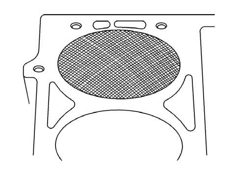
1.When honing the cylinder bores, follow the manufacturer’s recommendations for equipment use, cleaning and lubrication. • Use only clean sharp stones of the proper grade for the amount of material to be removed. • Dull, dirty stones cut unevenly and generate excessive heat. • DO NOT hone to a final grade with a coarse or medium- grade stone. • Leave sufficient metal so that all the stone marks will be remove with the fine grade stones. • Perform the final honing with a fine-grade stone and hone the cylinder bore in a crosshatch pattern at 45-65 degrees to obtain the proper clearance.
186747
2.During the honing operation, thoroughly check the cylinder bore. • Repeatedly check the cylinder bore fit with the selected piston. • All measurements of the piston or cylinder bore should be made with the components at normal room temperature. 3.When honing to eliminate taper in the cylinder bore, use full strokes the complete length of the cylinder bore. 4.Repeatedly check the measurement at the top, the middle and the bottom of the cylinder bore. • The finish marks should be clean but not sharp. • The finish marks should be free from imbedded particles or torn or folded material. 5.By measuring the selected piston at the sizing point and then by adding the average of the clearance specification, the final cylinder bore honing dimension required can be determined.
6. When finished, the reconditioned cylinder bores should have less than or meet the specified outof-round and taper requirements. 7. After the final honing and before the piston is checked for fit, clean the cylinder bore with hot water and detergent. • Scrub the cylinder bores with a stiff bristle brush. • Rinse the cylinder bores thoroughly with clean hot water. • Dry the cylinder bores with a clean rag. • Do not allow any abrasive material to remain in the cylinder bores. ■ Abrasive material may cause premature wear of the new piston rings and the cylinder bores. ■ Abrasive material will contaminate the engine oil and may cause premature wear of the bearings. 8. Perform final measurements of the piston and the cylinder bore. 9. Permanently mark the top of the piston for the specified cylinder to which it has been fitted. 10.Apply clean engine oil to each cylinder bore in order to prevent rusting.
Reboring the Cylinders NOTE
Important: Handle the pistons with care. Do not force the pistons through the cylinders until you hone the cylinder to the correct size. The piston can be distorted through careless handling.
1. To determine the size of the oversize piston to be used in all cylinders, choose the cylinder that requires the largest amount of reboring and use its size as the basis for all piston sizes. 2. Two kinds of oversize pistons are available; 0.50mm (0.02in.) O.S. and 1.00mm (0.039in.)
O.S. Those oversizes are based on the piston skirt O.D. measured along the datum line as shown in the figure. For all cylinders, select oversize pistons with the same diameter.
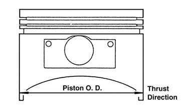
7EN268 3. From the piston O.D. measurement, calculate the valve of the cylinder bore to which every cylinder is to be rebored.
Rebore diameter = Piston O.D. + 0.02mm (8 x 10⁻⁴ in.) to 0.04mm (1.6 x 10⁻³ in.) (Cylinder-to-piston clearance) - 0.02 mm (8 x 10⁻⁴ in.) (honing allowance) 4. Rebore all cylinders to the calculated diameter.
NOTE
Reboring should be made in the order of the cylinders numbers to prevent warping due to excessive temperature.
5.With a hone, a.Recondition the cylinders that have less than 0.025mm (0.0010in.) wear or taper. b.Bore and hone the cylinders that have more than 0.025mm (0.0010in.) of wear or taper to the smallest oversize piston that will permit complete resurfacing of all the cylinders. 6. Hone the cylinders to the finished size (piston O.D. + piston-to-cylinder clearance). • During the honing operations occasionally: – Clean the cylinder bore. – Measure the cylinder bore for a proper piston fit.
Boring Procedure
! CAUTION
1.Before starting the honing or reboring operation, measure all the new pistons with the micrometer contacting at points exactly 90 degrees from the piston pin centerline.

188016
2.File the top of the cylinder block in order to remove any dirt or burrs before using any type of boring bar. 3.Follow the instructions furnished by the manufacturer regarding the use of the boring equipment. 4.When reboring the cylinders, make sure all the crankshaft bearing caps are installed in the original position and direction. 5.Tighten the crankshaft bearing caps to the proper torque specifications in order to avoid distortion of the cylinder bores in the final assembly. 6.When making the final cut with the boring bar, leave 0.03 mm (0.001 in) on the cylinder bore diameter for finish honing. This gives the required position to the cylinder clearance specifications. (Carefully perform the honing and boring operation in order to maintain the specified clearances between the pistons, the piston rings and the cylinder bores). 7.Check each cylinder for proper cylinder-to-piston clearance.
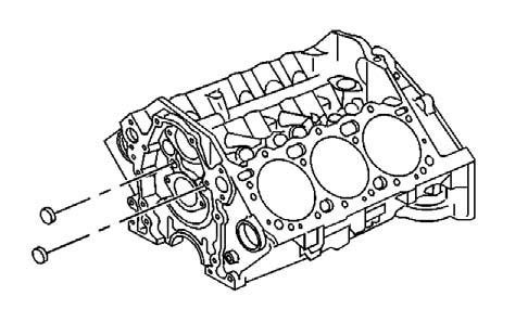
Engine Block Plug Installation
Installation Procedure Tools Required
• J 41712 Oil Pressure Switch Socket
! CAUTION
Wear safety glasses in order to avoid eye damage.
1.Install a new oil filter bypass valve. a.Install the oil filter bypass valve into the oil gallery bore until slightly below flush with the surface of the engine block. b.Using a pointed punch, stake the engine block area around the oil filter bypass valve. Stake in 3 locations 120 degrees apart. 2.Apply sealant MCF P/N 2I4256 GMP/N 12346004 or equivalent to the outside diameter of the new front engine oil gallery plugs. 3.Install the new front engine block oil gallery plugs. A properly installed front engine oil gallery plug must be installed slightly below flush with the front face of the engine block.
5270
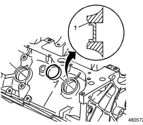
4.Apply threadlock GM P/N 12345382 or equivalent to the outside diameter of the NEW engine block core hole plugs. 5.Install the NEW engine block core hole plugs.
Properly installed engine block core hole plug must be installed flush with the bottom of the chamfer (1) of the engine block core hole.
6.Install the spring type S pin (crankshaft rear oil seal housing locator) (if required).
188023
334546
7.Apply sealant MCF P/N 2I4256/GMP/N 12346004or equivalent to the outside diameter of the new expansion cup plug (balance rear bearing hole). 8.Install the new expansion cup plug (balance shaft rear bearing hole).
182841
12.Install the dowel straight pins (transmission locator) (if required).
334540
9. Apply sealant MCF P/N 2I4256/GMP/N 12346004 or equivalent to the outside diameter of the new expansion cup plug (camshaft rear bearing hole). 10.Install the new expansion cup plug (camshaft rear bearing hole). 11.Apply sealant MCF P/N 2I4256 GMP/N 12346004 or equivalent to the threads of the engine block right rear oil gallery plug, the engine block left rear oil gallery plug, and the engine block left side oil gallery plug.
Tightening torque for left and right 2.08 Kgf•m (15 lb•ft) [20N•m] side rear oil gallery plugs
Tightening torque for left rear 3.05 Kgf•m (22 lb•ft) [30 N•m] oil gallery plug
334548
13.Install the left side dowel pins (cylinder head locator) (if required).
Tightening torque for engine block coolant drain 2.08 Kgf•m (15 lb•ft) [20N•m] hole plug
17.Apply sealant MCF P/N 2I4256/GMP/N 12346004 or equivalent to the threads of the engine oil pressure sensor fitting.
Important: Do not loosen the engine oil pressure fitting after the initial torque has been obtained.
Tightening torque for engine oil pressure sensor 1.52 Kgf•m (11 lb•ft) [15 N•m] fitting
334303
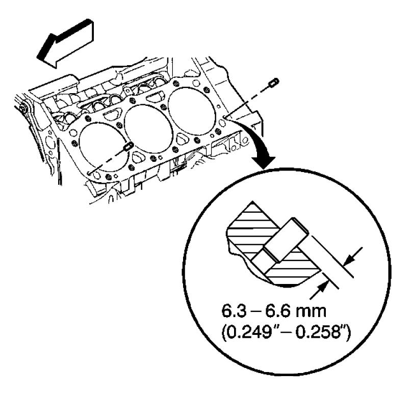
14.Install the right side dowel pins (cylinder head locator) (if required).
334314
15.Apply sealant MCF P/N 2I4256/GMP/N 12346004 or equivalent to the threads of the engine block coolant drain hole plug.
188052
NOTE
NOTE
Important: Do not rotate the engine oil pressure fitting clockwise more than 359 degrees after the initial torque has been obtained. 19.Rotate the engine oil pressure sensor fitting clockwise to the proper position (1) 50 degrees from the centerline.
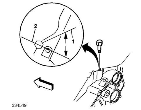
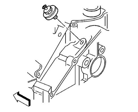
20. Apply sealant MCF P/N 2I4256/GMP/N 12346004 or equivalent to the threads of the engine oil pressure gauge sensor. 21.Install the engine oil pressure gauge sensor using the oil pressure switch socket J 41712. 22. Apply sealant MCF P/N 2I4256/GMP/N 12346004 or equivalent to the threads of the knock sensor.
Tightening torque for engine oil pressure gauge 3.05 Kgf•m (22 lb•ft) [30 N•m] sensor Tightening torque for 2.08 Kgf•m (15 lbf•ft) [20 N•m] knock sensor
10793
J 41712

188018


