14 minute read
Balancer and Camshaft
Removal and Installation
7 11
5
4 6 9 12 13
10
8 1
2
3
Removal steps
1. Rod 2. Guide 3. Lifter 4. Camshaft Gear 5. Gear Kit 6. Retainer 7. Retainer 8. Camshaft 9. Balancer 10. Bearing Kit - Camshaft 11. Bearing 12. Bearing 13. Plug
Tools Required
• J 23523-F Crankshaft Balancer Remover and
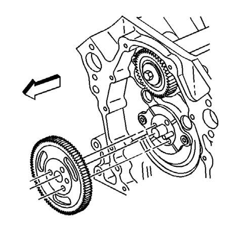
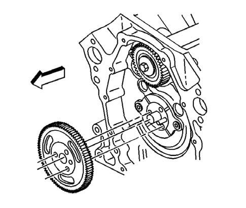
Installer • J 38834 Balancer Shaft Bearing Service Kit 1.Remove the balance shaft drive gear. Inspect the sprockets for chipped teeth and wear. Worn sprockets will wear a new chain.
9847 Important: The balance shaft drive and driven gears are serviced as a set. The set includes the balance shaft driven gear bolt.
5135
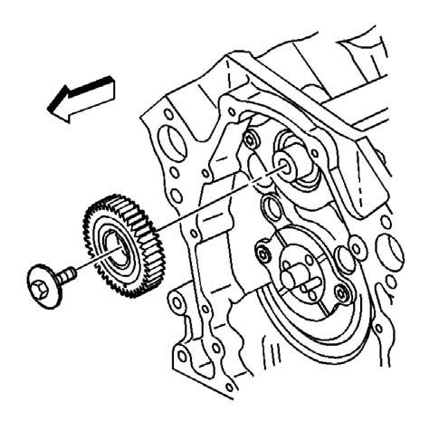
2. Remove the bolt and the balance shaft driven gear. Inspect the balance shaft drive and driven gears for nicks and burrs. a. Use a wrench in order to secure the balance shaft. Place the wrench onto the balance shaft near to the balance shaft front bearing. b.Remove the balance shaft bolt. c. Remove the wrench from the balance shaft 3. Remove the balance shaft driven gear from the balance shaft.
5136
5137
NOTE
Important: The balance shaft and the front bearing are serviced only as a package. Do not remove the front bearing from the balance shaft.
5. Use a soft-faced hammer to remove the balance shaft from the engine block.
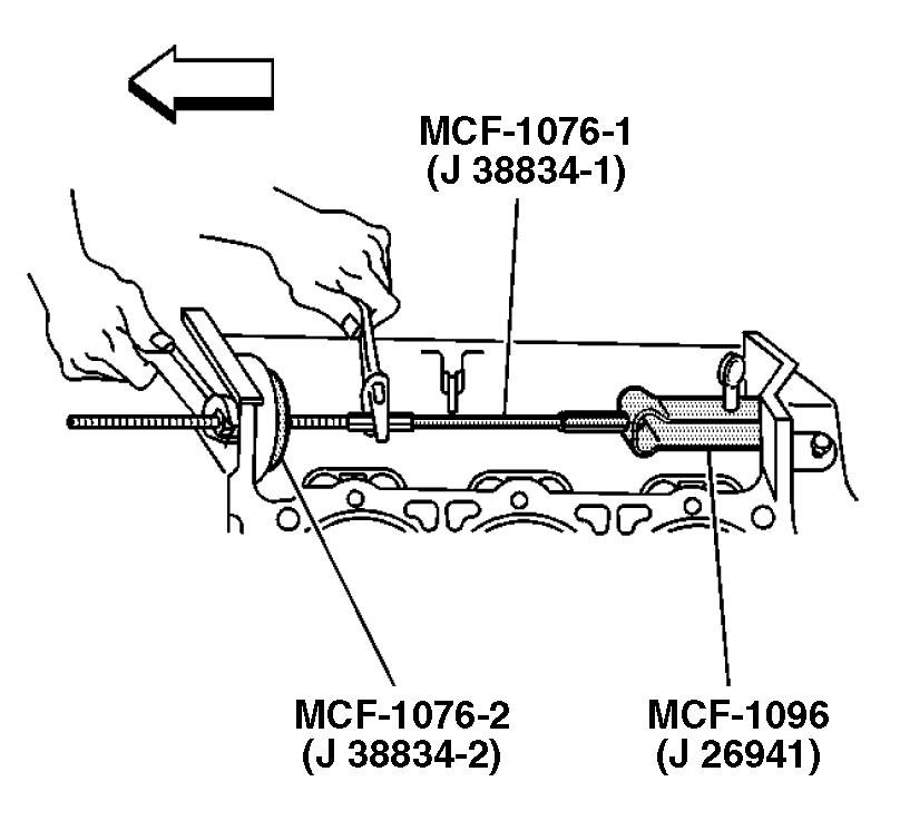
c. Install the J 38834-1 into the J 26941. d. Slide the J 37734-2 and into the balance shaft bore of the engine block. e. Install the J 38834 bearing, washer and nut onto the J 38834-1. f. Using a wrench, secure the J 38834-1 and then rotate the J 37734 nut clockwise until the balance shaft rear bearing is removed from the engine block. g. Remove the J 26941 from the balance shaft rear bearing. 7. Discard the balance shaft rear bearing.
J 38834-1
J 38834-2 J 26941
5139
5139
6. Use the balancer shaft bearing service kit J 38834 and the crankshaft balancer remover and installer J 26941 in order to remove the balance shaft rear bearing. a. Install the crankshaft balancer remover and installer J 26941 legs behind the balance shaft rear bearing and secure. b. Install the balancer shaft bearing service kit J 38834 with the short threaded end through the balance shaft bore in the front of the engine block.
Tools Required
•J23523-F Crankshaft Balancer Remover/Installer 1. Remove the camshaft retainer bolts and retainer.
5146
Notice:All camshaft journals are the same diameter, so care must be used in removing or installing the camshaft to avoid damage to the camshaft bearings. 2. Remove the camshaft. a.Install the three 6/16 x 4.0 inch bolts in the camshaft front bolt holes. b.Carefully rotate and pull the camshaft out of the bearings.
Tools Required
•J 33049 Camshaft Bearing Replacer
NOTE
Important: A loose camshaft bearing may be caused by an enlarged, out-of-round or damaged engine block camshaft bearing bore.
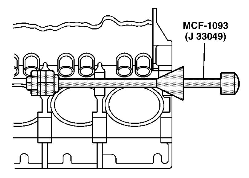
Important: Always remove the camshaft inner bearings #2 and #3 first. The camshaft outer bearings#1 and #4 serve as a guide for the camshaft bearing replacer J 33049.
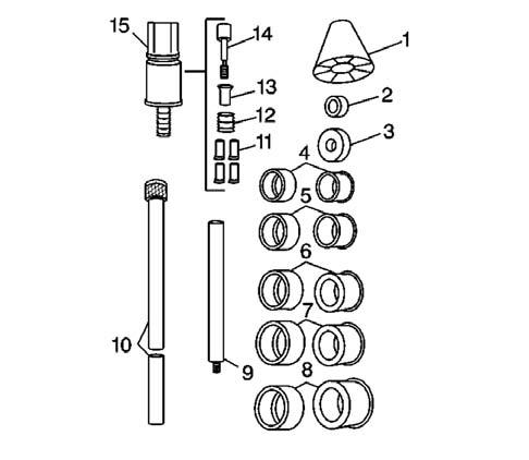
1.Select the cone (1), the handle (10), the expanding driver (4-8), the washer (2 or 3) and the expander assembly (15) from the J 33049 2. Assemble the J 33049.
NOTE
66100
5147
3.Remove the camshaft inner bearings #2 and #3. a.Insert the camshaft bearing replacer J 33049 through the front of the engine block and into the camshaft inner bearing #2. b.Tighten the J 3304) expander assembly nut until snug. c.Push the J 33049 guide cone into the camshaft front bearing in order to align the
J 33049. d.Drive the camshaft inner bearing #2 from the camshaft inner bearing bore #2. e.Loosen the J 33049 expander assembly nut. f.Remove the camshaft inner bearing #2 from the J 33049 expander assembly. g.Insert the J 33049 expander assembly into the camshaft inner bearing #3. h.Tighten the J 33049 expander assembly nut until snug. i. Push the J 33049 guide cone into the camshaft front bearing in order to align the
J 33049. j. Drive the camshaft inner bearing #3 from the camshaft inner bearing bore #3. k.Loosen the J 33049 expander assembly nut. l. Remove the camshaft inner bearing #3 from the J 33049 expander assembly.
J 33049
4.Remove the camshaft bearing replacer J 33049 from the engine block. 5.Remove the camshaft outer bearing #1 and #4. a.Insert the J 33049 into the camshaft outer bearing #1. b.Tighten the J 33049 expander assembly nut until snug. c.Drive the camshaft outer bearing #1 from the camshaft outer bearing bore #1. d.Loosen the J 33049 expander assembly nut. e.Remove the camshaft outer bearing #1 from the J 33049 expander assembly. f.Remove the J 33049 from the engine block. g.Insert the J 33049 expander assembly into the camshaft outer bearing #4. h.Tighten the J 33049 expander assembly nut until snug. i. Drive the camshaft outer bearing #4 from the camshaft inner bearing #4. j. Loosen the J 33049 expander assembly nut. k.Remove the camshaft outer bearing #4 from the J 33049 expander assembly. 6.Remove the camshaft bearing replacer J 33049 from the engine block. 7.Discard the camshaft bearings.
4985
J 33049

63219
Camshaft and Bearings Clean and Inspect
Tools Required
•J 7872 Magnetic Base Indicator Set 1.Clean the engine camshaft in cleaning solvent. 2.Dry the engine camshaft with compressed air. 3.Inspect the camshaft retainer plate for damage.
If the camshaft retainer plate is damaged, replace as necessary. 4.Inspect the camshaft bearings for correct fit into the engine block camshaft bearings bores.
The camshaft bearings have an interference fit to the engine block camshaft bearing bores and must not be loose in the engine block camshaft bearing bores.

334499
NOTE
Important: If any camshaft bearing is excessively worn or scored, replace all the camshaft bearings.
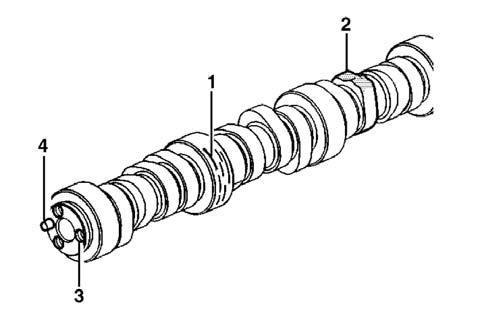
5.Inspect the camshaft bearings for excessive wear or scoring. 6.Inspect the engine camshaft for the following: • Worn, scored or damaged bearing journals (1) • Worn engine camshaft lobes (2) • Damaged bolt hole threads (3) • Damaged camshaft sprocket locator pin (4)
188095 7.Measure the engine camshaft journals with a micrometer. If the camshaft journals are more than 0.025 mm (0.0010 in) out-of-round, then replace the engine camshaft.

188014
8.Measure for a bent engine camshaft or excessive engine camshaft run out using the magnetic base indicator J7872. • Mount the engine camshaft in a suitable stand between centers. • Use the magnetic base indicator J7872 to check the intermediate engine camshaft journals. 9.Measure the engine camshaft lobe lift using the magnetic base indicator J7872. • Place the engine camshaft on the V-blocks. • Use the magnetic base indicator J7872 to measure the engine camshaft lobe lift. 10. Replace the engine camshaft if the engine camshaft lobe lift is not within specifications.
Refer to General Specifications.
Tools Required
•J 33049 Camshaft Bearing Service Kit
NOTE
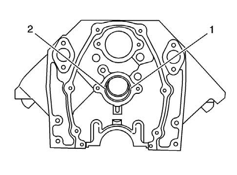
Important: When installing the camshaft bearings, always make sure that the camshaft bearing lubrication hole is located above the 3 o’clock position (1) or the 9 o’clock position (2). The proper positioning of the camshaft bearing lubrication hole is in order to ensure the best lubrication of the engine camshaft journals.
594647
1.Select the handle (10), the expanding driver (4-8), the washer (2 or 3) and the expander assembly (15) from the camshaft bearing service kit J 33049. 2.Assemble the camshaft bearing service kit
J 33049.

66100 Important: The camshaft bearings vary in size. When ordering the new camshaft bearings, be sure to order the correct camshaft bearings for the application to be serviced. Always install the camshaft outer bearings #1 and #4 first. The camshaft outer bearings serve as a guide for the camshaft bearing service kit J 33049 and help center the camshaft inner bearings during the installation process.
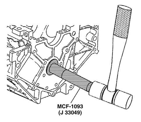
3.Install the NEW camshaft outer bearings #4 and #1. a.Install the NEW camshaft outer bearing #4 onto the J33049 expander assembly. b.Tighten the J 33049 expander assembly nut until snug. c.Align the lubrication hole of the camshaft outer bearing #4 above the 3 o’clock position or the 9 o’clock position of the camshaft outer bearing bore #4 at the rear of the engine block. d.Drive the camshaft outer bearing #4 into the camshaft outer bearing bore #4 at the rear of the engine block. e.Loosen the J 33049 expander assembly nut. f.Remove the camshaft outer bearing #4 from the J 33049 expander assembly. g.Install the NEW camshaft outer bearing #1 onto the J33049 expander assembly. h.Tighten the J 33049 expander assembly nut until snug. i. Align the lubrication hole of the camshaft outer bearing #1 above the 3 o’clock position or the 9 o’clock position of the camshaft outer bearing bore #1 at the front of the engine block. j. Drive the camshaft outer bearing #1 into the camshaft outer bearing bore #1 at the front of the engine block. k.Loosen the J 33049 expander assembly nut. l. Carefully slide the J 33049 into the engine block until the J 33049 expander assembly is positioned between the camshaft inner bearing bores.
J 33049
63219
J 33049
4985
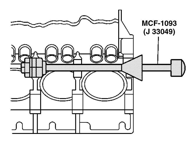
4.Install the NEW camshaft inner bearings #3 and #2. a.Install the NEW camshaft inner bearing #3 onto the J33049 expander assembly. b.Align the lubrication hole of the camshaft inner bearing #3 above the 3 o’clock position or the 9 o’clock position of the camshaft inner bearing bore #3 of the engine block. c.Push the J 33049 guide cone into the camshaft front bearing bore #1 in order to align the J 33049. d.Drive the camshaft inner bearing #3 into the camshaft inner bearing bore #3 of the engine block. e.Loosen the J 33049 expander assembly nut. f.Carefully slide the J 33049 until the J33049 expander assembly is positioned between the camshaft inner bearingbore #2 and the camshaft outer bearing bore #1.
g.Install the NEW camshaft inner bearing #2 onto the J33049 expander assembly. h.Tighten the J 33049 expander assembly nut until snug. i. Align the lubrication hole of the camshaft inner bearing #2 above the 3 o’clock position or the 9 o’clock position of the camshaft inner bearing bore #2 of the engine block. j. Push the J 33049 guide cone into the camshaft front bearing bore #1 in order to align the J 33049. k.Drive the camshaft inner bearing #2 into the camshaft inner bearing bore #2 of the engine block. l. Loosen the J 33049 expander assembly nut. 5.Carefully remove the J 33049 from the engine block. 6.Install a new camshaft rear bearing hole plug. Coat the outside diameter of the plug with MCF P/N 2I4256 (GM P/N 12346004) sealant or equivalent. a.Install the plug flush to 0.80 mm (1/32 in.) b.Install the plug while RTV is still wet.
Camshaft Installation
1.Apply clean engine oil or equivalent, to the following components: • The engine camshaft lobes • The camshaft bearing journals • The camshaft bearings 2.Install three 5/16-18 x 4.0 in. bolts into the engine camshaft front bolt holes.
NOTE
Important: All camshaft journals are the same diameter, so care must be used in removing or installing the camshaft to avoid damage to the camshaft
5147
3.Use the bolts as a handle in order to install the engine camshaft. 4.Remove the 3 bolts from the front of the engine camshaft. 5.If reusing the fasteners, apply thread lock GM
P/N 12345382 or equivalent to the threads of the camshaft retainer bolts. 6.Install the camshaft retainer and bolts.

188030
Tightening torque for Camshaft 1.22Kgf•m (106 lb•in) [12N•m]
Retainer bolts Important: The balance shaft and the balance shaft front bearing are serviced only as an assembly. Do not remove the balance shaft front bearing from the balance shaft.
188106
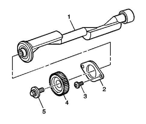
1.Clean the following components in cleaning solvent. • The balance shaft (1) • The balance shaft retainer (2) • The balance shaft rear bearing • The balance shaft driven gear (4) • The balance shaft drive gear 2. Dry the following components with compressed air. • The balance shaft (1) • The balance shaft retainer (2) • The balance shaft rear bearing • The balance shaft driven gear (4) • The balance shaft drive gear 3. Inspect the balance shaft bearings for the following: • Front ball bearing for damage or wear • Front ball bearing for smoothness of operation • Rear sleeve bearing for wear, scoring or other damage. 4.Inspect the balance shaft (1) for the following: • Wear or scoring on the rear bearing journal • Damaged bolt hole threads • Damage to the balance shaft driven gear locator pin 5.Inspect the balance shaft retainer (2) for wear or damage 6.Inspect the balance shaft retainer bolts (3) for damaged threads. 7.Inspect the driven gear (4) for the following: • Excessive wear or damage • Nicks, burns or scoring
8.Inspect the driven gear bolt (5) for damaged threads. 9. Inspect the balance shaft drive gear for the following: • Excessive wear or damage • Nicks, burns or scoring


9848
Balance Shaft Bearing and/or Bushing Installation
Tools Required
• J 38834 Balance Shaft Service Kit 1.Use the J 38834 in order to install the balance shaft rear bearing. a.Install the J 38834-3 onto the short threaded end of the J 38834-1. b.Install the J 38834 nut, the washer and the bearing on the long threaded end of the
J 38834-1. c.Install the J 38834-2 onto the J 38834-1 so that the smaller diameter of the J 38834-2 will be facing the front of the engine block. d.Install the J 38834-2 on the inside of the balance shaft front bearing bore. e.Lubricate the NEW balance shaft rear bearing with clean engine oil. f.Install the balance shaft rear bearing onto the
J 38834-2. g.Align the balance shaft rear bearing for installation. h.Using a wrench, secure the J 38834- into place. i. Rotate the J 38834 until the balance shaft rear bearing is properly and completely pushed into the balance shaft rear bearing bore.
J 38834-1
J 38834-3
J 38834-2
340085
Balance Shaft Installation
Tools Required
• J 36996 Balance Shaft Installer. • J 8092 Universal Driver Handle. • J 36660 Torque/Angle Meter. Important: The balance shaft and the balance shaft front bearing are serviced only as an assembly. Do not remove the balance shaft front bearing from the balance shaft. 1. Apply clean engine oil or equivalent to the balance shaft front bearing. 2. Use the balance shaft installer J 36996 and the universal drive handle J 8092 in order to install the balance shaft.
J 8092 J 36996
5141
Tightening Torque for Balance 1.22Kgf•m (106 lb•in) [12N•m]
Shaft bolts
188031
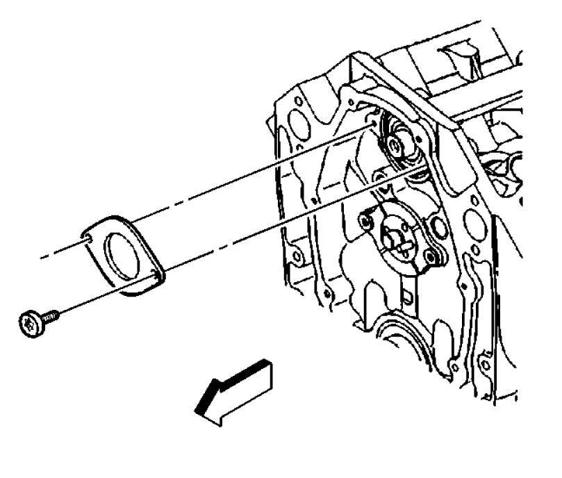
4. Install the balance shaft driven onto the balance shaft. 5. If reusing the fastener, apply thread lock MCF P/N 2I4264, GM P/N 12345382 or equivalent to the threads of the balance shaft driven gear bolt. 6. Install the balance shaft driven gear bolt. a.Use a wrench to secure the balance shaft. b.Place the wrench onto the balance shaft near to the balance shaft front bearing. c.Install the balance shaft driven gear bolt.
Tightening Torque for Balance Shaft Driven gear bolt 2.08 Kgf•m (15 lb ft) [20N•m]
First Pass
Tightening Torque for Balance Shaft Driven gear bolt Final Pass 35° 7. Remove the wrench from the balance shaft. 8. Rotate the balance shaft by hand in order to ensure that there is clearance between the balance shaft and the valve lifter pushrod guide.
If the balance shaft does not rotate freely, check to ensure that the retaining ring on the balance shaft front bearing is seated on the case.
5136
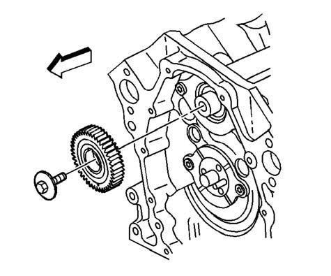
9. Install the balance shaft drive gear. DO NOT install the camshaft sprocket bolts at this time.
9847
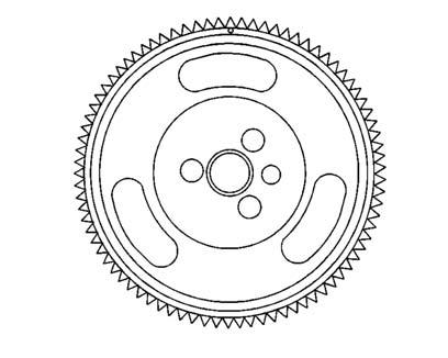
10.Rotate the engine camshaft so that the timing mark on the balance shaft drive gear is in the 12 o’clock position.
9848
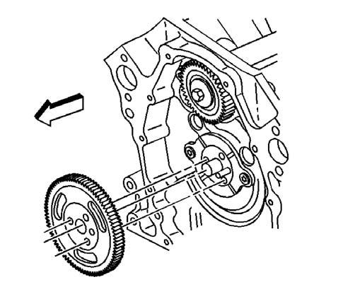
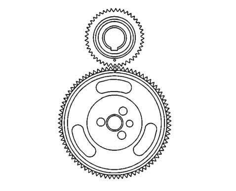
11.Remove the balance shaft drive gear. 12.Rotate the balance shaft so that the timing mark on the balance shaft driven gear is in the 6 o’clock position.
13.Position the balance shaft drive gear onto the engine camshaft. 14.Look to ensure that the balance shaft drive gear and the balance shaft driven gear timing marks are aligned.
9847 9849

5144


