2 minute read
Intake Manifold
Removal and Installation
N
Torque Specifications First pass:.31 kgf•m (27 lb•in) [3 N•m] Second pass:1.22 kgf•m (106 lb•in) [12 N•m] Third pass: 1.52 kgf•m (11 lb•ft) [15 N•m]
➧B➧ ➧A➧
Removal steps
1. Cover - Thermostat 2. Gasket 3. Thermostat 4. Manifold 5. Gasket
N
NOTE
Important: Make sure the ends of the fuel system lines are properly sealed. Do not allow dirt or debris to enter the fuel system.
1. Drain the engine coolant. 2. Remove the distributor clamp and bolt. 3. Remove the distributor.
4. Remove the air inlet duct. 5. Remove the throttle linkage. 6. Remove the ignition coil. 7. Remove PCV valve and vacuum hoses. 8. Remove the intake manifold bolts.
Important: The intake manifold may be removed as an assembly. Do not remove the intake manifold components unless component service is required.
34403
NOTE
10.Remove and discard the intake manifold
31510
Intake Manifold Clean and Inspect
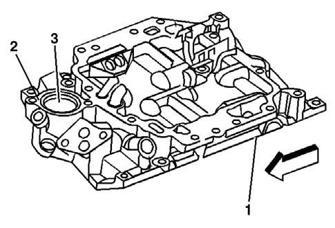
1. Clean the intake manifold in cleaning solvent. 2. Dry the intake manifold with compressed air. 3. Inspect the intake manifold for the following: • Damage to the gasket sealing surfaces (1), (2) • Restricted exhaust gas recirculation system passages • Restricted cooling system passages (3) • Cracks or damage
480570
NOTE
Important: Applying excessive amounts of sealant may prohibit the intake gasket from sealing properly.
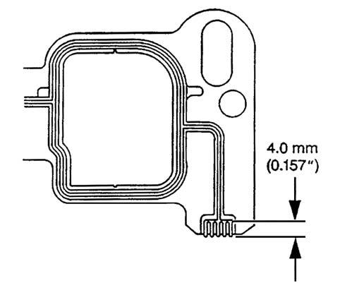
1. Apply a 4.0 mm (0.157 in.) patch of adhesive patch of sealant P/N A000000165 (GM 12346141) or equivalent to the cylinder head side of the lower intake manifold gasket at each end front top of the engine block.

NOTE
Important: The intake manifold must be installed and the fasteners tightened while the adhesive is still wet to the touch. 2. Install the lower intake manifold gasket onto the cylinder head. Use the gasket locator pins to properly seat the intake manifold gasket on the cylinder head.
Note: Care must be used to apply the correct amountof sealant onto the gaskets. Applying excessive amounts of sealant may prohibit the intake gaskets from sealing properly.
b.Install the intake manifold on to engine block. c.Apply threadlock (GM P/N12345382) or equivalent to the threads of the intake manifold bolts. 4. Install the intake manifold bolts in sequence and torque in the 3 step method.
NOTE
3. Apply a 5 mm (0.197 in.) bead of sealant MCF
P/N A000000165 (GM P/N12346141) or equivalent to the front and rear top of the engine block intake mounting surface. a.Extend the sealant bead 13 mm (0.50 in.) onto the intake manifold gasket. Front and rear of the engine block.
31510
Important: Proper manifold fastener tightening sequence and torque are critical. Always follow the tightening sequence and torque the intake manifold bolts using the three (3) step method. Failing to do so may distort the crankshaft bearing bore alignment and cause damage to the crankshaft bearings. 5. Tighten the manifold bolts as shown below.
1st pass .31 Kgf•cm (27 lbf.in) [3 N•m] Tightening torque 2nd pass for intake 1.22 Kgf•cm (106 lbf.in) [12 N•m] manifold Final pass 1.52 Kgf•cm (11 lbf.ft) [15 N•m]


