6 minute read
Monitoring System


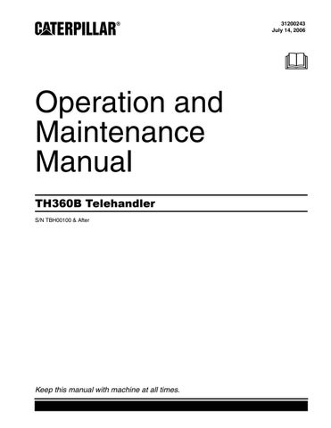
Picking up the Hopper
Position the machine square to the hopper. Extend and lower the boom. The forks must enter the pockets of the hopper cleanly. The forks must be fully engaged with the pockets of the hopper.
Illustration 133 g00974805
When the forks fully engage, a bar that is spring loaded will lock each fork in position. Establish that the forks are securely locked in place before you raise the hopper. Before you raise the hopper, ensure that the latch for the trip lever is securely engaged. Raise the hopper. Tilt the quick coupler slightly backward in order to better secure the hopper. Travel with the boom fully retracted so that you have good visibility and so that the machine has good stability.
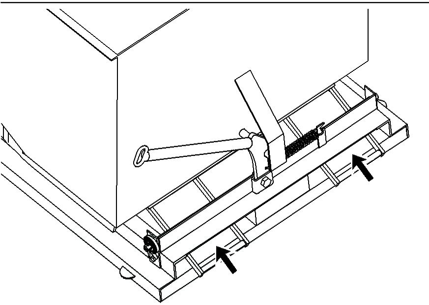
Discharging the Hopper
Travel the machine to the work area. Stop the machine and apply the parking brake. Lower the hopper.
Illustration 134 g00974801
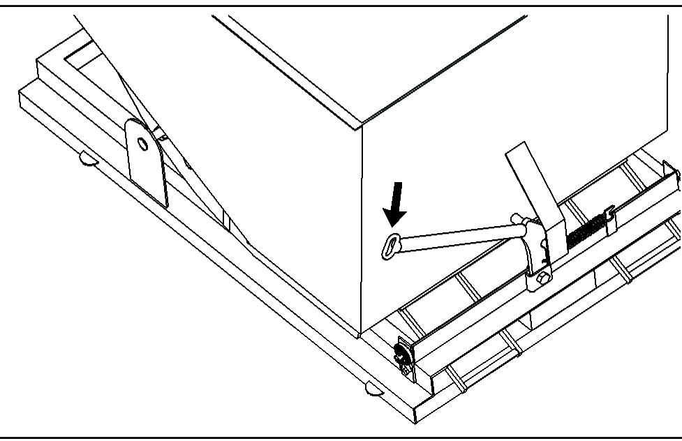
Pull down on the release lever. The hopper will tilt forward and the load will be discharged. To remove the hopper, lower the hopper to the ground. The bar that secures the forks in place will automatically disengage when the hopper is placed on the ground. Withdraw the forks from the pockets by retracting the boom.
Broom
Illustration 135 g01015331
Refer to Operation and Maintenance Manual, SEBU7740, "BP24 Broom Work Tool EAK" for information on the installation of the broom and the operation of the broom.
Alert Indicators
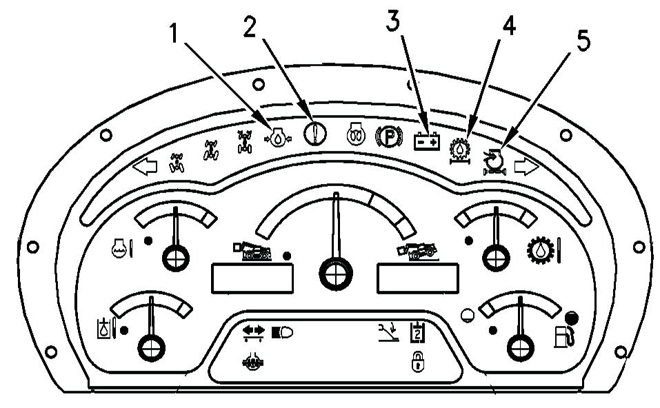
Illustration 136 g01002552
Engine Oil Pressure (1) -This indicator illuminates when the engine oil pressure is low.
Action Lamp (2) -This indicator will illuminate when a failure that is a warning category 2 or a higher warning occurs. If the lamp is illuminated, the machine needs to be serviced soon. The color of this indicator can be amber or red. An audible alarm may also sound when this indicator is illuminated. When a warning category 2 occurs, the action lamp flashes red and there is no audible alarm. In order to prevent severe damage to components, the operator is required to change the machine operation or the operator is required to perform maintenance to the machine.
When a warning category 2S occurs, the action lamp flashes red and there is a constant audible alarm. In order to prevent severe damage to components, the operator is required to change the machine operation. When a warning category 3 occurs, the action lamp flashes red and there is an intermittent audible alarm. In order to prevent personal injury or severe damage to components, the operator is required to perform a safe engine shutdown. When the machine has been configured with no model designation, indicator (2) flashes amber and no audible alarm will sound. This condition will not log an error code. When the data link is not communicating with the display unit, indicator (2) flashes amber and no audible alarm will sound. This condition will log an error code. Battery Condition (3) - This indicator illuminates when the battery is not receiving a charge from the alternator.
Combined Transmission and Hydraulic Oil
Filter (4) - This indicator illuminates when the transmission oil filter needs to be
Engine Air Filter (5) - This indicator illuminates when the engine air filter needs to be replaced.
Indicators
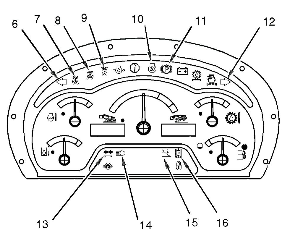
Illustration 137 g01014331
Left Turn Signal (6) - This indicator flashes when the left turn signal is operating. Circle Steer (7) - This indicator is illuminated when circle steer mode is selected.
Crab Steer (8) - This indicator is illuminated when crab steer mode is selected.
Two-Wheel Steer (9) - This indicator is illuminated when two-wheel steer mode is selected. Engine Starting Aid (10) - This indicator is illuminated when the engine starting aid is switched on. Parking Brake Indicator (11) - This indicator illuminates when the parking brake is engaged.
Right Turn Signal (12) - This indicator flashes when the right turn signal is operating.
Trailer Turn Signals (13) - This indicator flashes when a trailer turn signal is operating.
High Beam (14) - This illuminates when the high beam headlights are switched on.
Stabilizers (15) - This light indicates when the stabilizers are lowered.
Hydraulic Auxiliary 2(16) -This indicates when the solenoids on the diverter valve have been energized in order to divert oil flow to the second auxiliary circuit.
Gauges
These gauges are used to help the operator to monitor trends in machine operation or changes in machine operation.
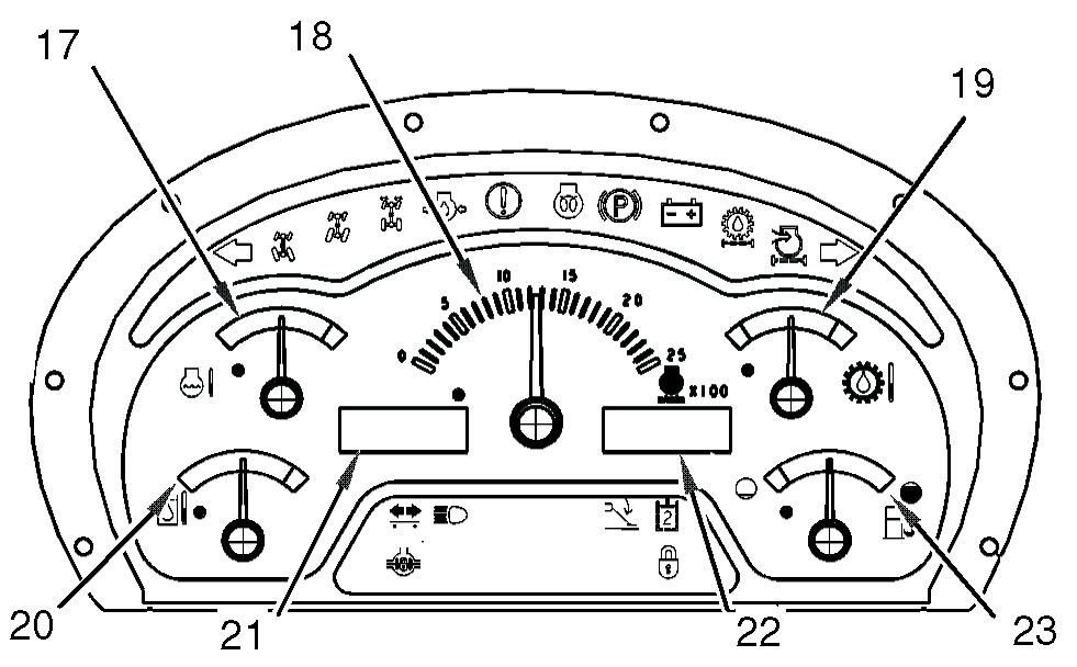
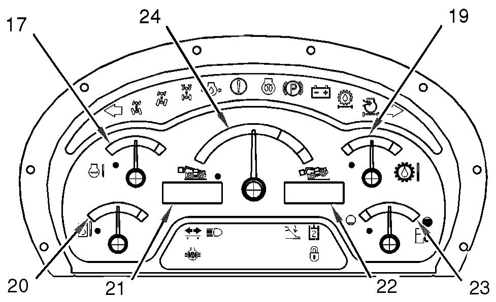
Illustration 139 g01014335 Display panel with longitudinal stability indicator
Engine Coolant Temperature (17) - This gauge indicates the temperature of the engine coolant. The green zone indicates that the engine coolant temperature is normal. The red zone indicates that the engine coolant is overheating. If the gauge indicates overheating, stop the engine. Investigate the cause. Check the coolant level. Check that the fan drive belt is not broken or loose. Check that the radiator fins are clean. Tachometer (18) - This gauge indicates the speed of the engine in revolutions per minute, if equipped. Refer to Illustration Torque Converter Oil Temperature (19) This gauge indicates the temperature of the transmission and hydraulic system oil after the oil has passed through the torque converter. The green zone indicates that the temperature of the transmission and hydraulic system oil is normal. The red zone indicates that the torque converter temperature is overheating. Hydraulic Oil Temperature (20) - This indicates the temperature of the transmission and hydraulic system oil in the sump. The green zone indicates that the temperature of the transmission and hydraulic system oil temperature is normal. The red zone indicates that the transmission and hydraulic system oil is overheating. Speedometer (21) - This digital display indicates the current speed of the machine.
Service Hour Meter (22) - This digital display indicates the total operating hours of the engine. The service hour meter should be used to determine the service hour maintenance intervals. Fuel Level (23) - This gauge indicates the amount of fuel that is left in the fuel tank. When the needle on the fuel gauge reaches the red area the fuel tank should be filled. Longitudinal Stability Indicator (24) - This gauge indicates the longitudinal stability of the machine, if equipped. Refer to Illustration 139. Refer to "Longitudinal Stability Indicator" for more information.
Longitudinal Stability Indicator
Operating the machine beyond its stability limit could result in a tip over or failure of the work tool. Check the proposed lift with the load chart. Do not attempt the lift if the longitudinal stability limit of the machine will be exceeded. Tip over or failure of the work tool could cause personnel injury or death.
Your machine may be equipped with a longitudinal stability indicator. The longitudinal stability indicator provides audible signals and visual signals in order to indicate the limit of the forward stability of the machine, if equipped. The audible signal is shared with other system failures. Refer to Operation and Maintenance Manual for usages of the audible signal. The longitudinal stability indicator is powered by the machine electrical system which is activated when the engine start switch key is turned to the ON position. Ensure that a Caterpillar work tool is attached to the machine and use the correct load chart in order to verify that the intended lift operation is within the capability of the machine. Refer to Operation and Maintenance Manual, "Lifting Capacities" for the location of the load charts. The forward stability of the machine will depend on the following factors: • Weight of the attachment • Weight of the load • Angle of the boom • Length of the boom • The position of the stabilizers (if equipped)
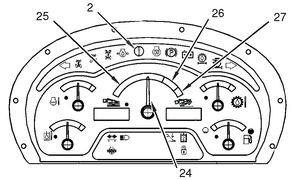
Illustration 140 g01014337
The longitudinal stability indicator has a variable gauge (24) that indicates the longitudinal stability of the machine. The indicator shows the status of the attempted lift operation in comparison to the limit of the