42 minute read
Operator Controls


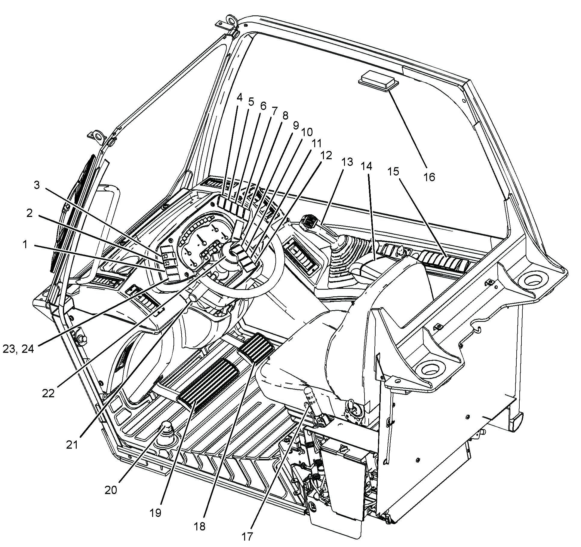
Illustration 62
((1) Quick coupler control (2) Transmission neutralizer control (3) Steering mode control (4) Frame leveling control (5) Left stabilizer control (6) Right stabilizer control (7) Continuous auxiliary flow control (8) Fog lights (9) Hazard flashers (10) Headlight dimmer switch (11) Headlight-Parking lights (12) Rotating beacon light (13) Joystick control (14) Adjustable armrest (15) Side console (16) Interior light (17) Parking and secondary brake control (18) Accelerator control (19) Service brake control (20) Differential lock control (21) Transmission control (22) Horn (23) Starting aid switch (24) Auto/Manual switch (if equipped)
g01213390
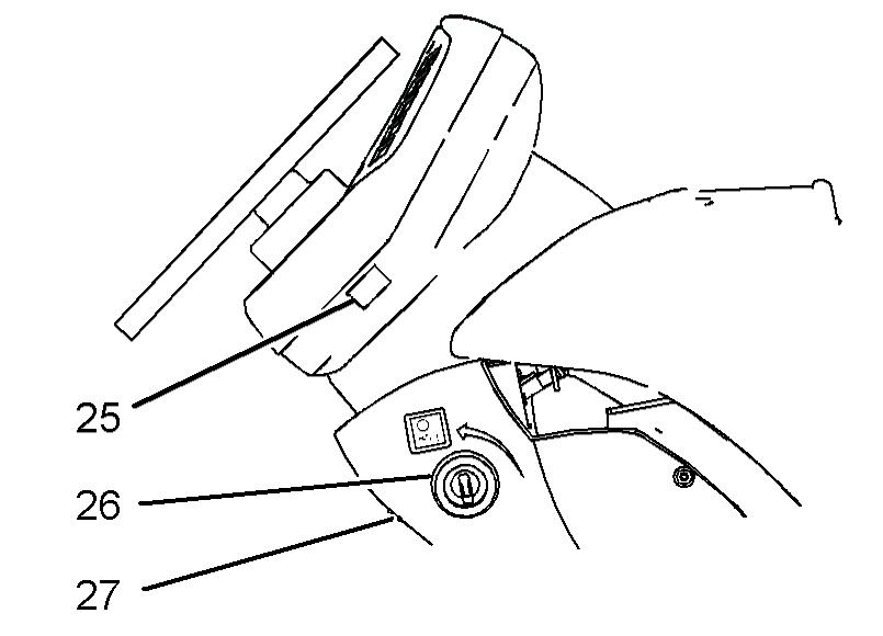
Illustration 63 (25) Directional turn signal control (26) Engine start switch (27) Steering column tilt control g01111001
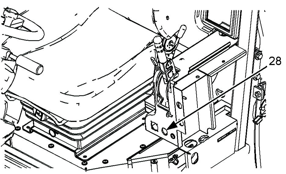
Illustration 64 (28) Power receptacle g01053554
Note: Your machine may not be equipped with all of the controls that are described in this topic.
Quick Coupler Control (1)
Quick Coupler Control - This is a three-position switch, if equipped. When switch (1) is released the switch will return to the HOLD position. Disengage - Move the red slider on switch (1) downward, and push the top of switch (1). Hold the top of switch (1) until the quick coupler pins are fully disengaged.
Hold - When switch (1) is released the switch will return to the HOLD position. Engage - Press the bottom of switch (1). Hold the bottom of switch (1) until the quick coupler pins are fully engaged.
Transmission Neutralizer Control (2)
If the transmission neutralizer control switch is in the ON position and the service brake control pedal is pressed, the transmission will shift into NEUTRAL. When the service brake control pedal is released it will take a short period of time for the transmission to reengage the original gear. If the machine is on a hill during this time, the machine can roll forward or the machine can roll backward. The unexpected movement of the machine could cause personal injury or death. Refer to Operation and Maintenance Manual, "Transmission Control" for additional information.
Transmission Neutralizer Control -This is a two-position switch, if equipped.Push the top of switch (2) in order for the transmission neutralizer to be operational. A lamp inside the switch will be illuminated. The transmission will be neutralized whenever the service brake is applied. Push the bottom of switch (2) in order for the transmission to remain engaged whenever the service brake is applied.
Steering Mode Control (3)
Personal injury or death can result if the machine is roaded in any mode other than two-wheel steer. Always road the machine with the rear wheels centered and the machine in the two-wheel steer mode.
NOTICE To avoid possible damage to the steering system, always center the rear wheels before operating the machine in the two-wheel steer mode. It is important to check the alignment of the wheels at least once per day. Failure to do this may result in reduced accuracy in the steering system. Steering Mode Select Switch - This threeposition switch controls the steering mode. Push the top of switch (3) in order to select crab steer. Set switch (3) to the middle position in order to select circle steer. Push the bottom of switch (3) in order to select two-wheel steer. Note: Always move the front wheels and the rear wheels to the straight ahead position before you change the steering modes.
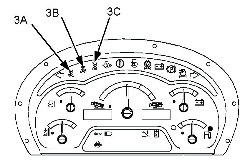
Illustration 65 g01014284 Circle Steer Mode - When circle steer mode is selected, indicator (3A) is illuminated.
Crab Steer Mode - When crab steer mode is selected, indicator (3B) is illuminated.
Two-Wheel Steer Mode - When two-wheel steer mode is selected, indicator (3C) is illuminated.
Use of Steering Modes
The machine can be operated in the following steering modes: • Two-Wheel Steer • Circle Steer • Crab Steer Only the front wheels are steered in two-wheel steer mode. This mode must be used when you road the machine. Use circle steer mode for normal operation. When the machine is in circle steer mode, the front wheels and the rear wheels turn in opposite directions. This allows the machine to make tighter turns. When the machine is in crab steer mode, the front wheels and the rear wheels turn in the same direction. When you select the crab steer mode, the machine will move forward and the machine will move to one side. Alternatively, the machine will move backward and the machine will move to one side. This allows the machine to operate in confined locations.
Checking or Synchronizing the Wheels Machines with Steer Sensors
1. In a static position, select circle steer mode and ensure that the circle steer mode indicator is constantly illuminated. Adjust the steering wheel, as required. 2. Select two-wheel steer mode and ensure that the two-wheel steer mode indicator is constantly illuminated. Adjust the steering wheel, as required. 3. Select your desired steer mode and use as normal.
Machines without Steer Sensors
1. In a static position, select circle steer mode. By using your eyes, align the rear wheels to a straight position. 2. Select two-wheel steer mode. By using your eyes, align the front wheels to a straight position. 3. Select your desired steer mode and use as normal. Note: It is important not to try to turn the steering wheel once the ignition is turned to the OFF position. This can lead to steer misalignment, which will result in reduced accuracy of the steering system.
When you change the steering mode, it is possible for the steering to go out of synchronization. This will happen under the following conditions: • The rear wheels are not positioned straight when you change from circle steer mode to two-wheel steer mode. • The rear wheels are not positioned straight when you change from crab steer mode to two-wheel steer mode. • All four wheels are not positioned straight when you change from circle steer mode to crab steer mode. • All four wheels are not positioned straight when you change from crab steer mode to circle steer mode. Use the following procedure in order to synchronize the steering: 1. 1. Stop the machine while either crab steer mode or circle steer mode is selected.
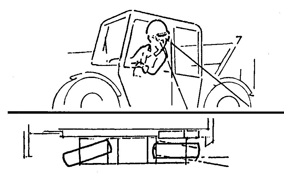
Illustration 66 g00603627
2. Turn the steering wheel until the left rear wheel is in line with the side of the machine.
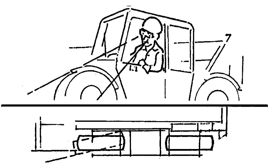
Illustration 67 g00603632 2. Change to two-wheel steer and turn the steering wheel until the left front wheel is in line with the side of the machine. 3. Change to either crab steer mode or circle steer mode, as required.
Your machine may be equipped with self-aligning rear steering. The self-aligning feature ensures that the rear wheels are aligned before the steering mode is changed. When switch (3) is pressed by the operator, the machine will not change to the desired steering mode unless the rear wheels are in the straight ahead position. If switch (3) is pressed by the operator and the rear wheels of the machine are not aligned, the current steering mode will remain selected. The indicator for the current steering mode on the display panel will remain on, and the desired mode indicator will flash. When the rear wheels are moved to the straight ahead position by the operator, the steering mode will then change to the desired mode.
Frame Leveling Control (4)
Improper use of the frame leveling control could result in personal injury or death. Always level the machine frame and load before raising the boom. Never use the frame leveling control when the boom is raised with a load or without a load. Never use the frame leveling control to increase the sideways slope of the machine frame.
If equipped, the frame leveling control (switch) is a three-position switch. The frame leveling control is used to level the machine when the machine is on an uneven surface. The frame leveling control can cause the frame to tilt to the left or to the right. The maximum amount of tilt is 10 degrees in either of these directions. Lower the boom before you use the frame leveling control. The boom must be close to the ground. Press the right side of the switch in order to lower the right side of the frame. The frame rotates clockwise in relation to the axles. Press the left side of the switch in order to lower the left side of the frame. The frame rotates counterclockwise in relation to the axles. When the switch is released, the frame leveling control returns to the HOLD position. Use the level indicator to determine when the frame is level. The frame is level when the bubble is in the middle of the sight glass.
Frame Level Interlock (If Equipped)
When the boom is extended outward, the frame level will be isolated. The operator will not be able to use the frame level function until the boom has been fully retracted. The operation of the Frame Level Interlock will not affect any other functions of the machine hydraulics.
Stabilizer Controls (5), (6)
Machine instability could result if the following conditions are not observed: The proper load chart is used. The capacities that are shown on the load charts are not exceeded. The boom is fully retracted and lowered to the travel position before raising the stabilizers. The areas adjacent to the stabilizers are clear and will provide uniform support for weight of the machine and intended load. The machine is not leveled using the frame level control when the stabilizers are lowered. The stabilizers are not used except as described in the following instructions. Incorrect use of stabilizers could result in injury or death.
Do not operate the stabilizers when personnel are nearby. Ensure that personnel stand clear when the stabilizers are being raised or lowered. Ensure that both stabilizers are fully raised before moving the machine. Operating the stabilizers when personnel are nearby could result in personal injury or death.
Left Stabilizer (5) (if equipped) - This is a spring return switch with three positions. Push the right of the switch in order to raise the left stabilizer. Release the switch in order to stop the stabilizer from rising. The switch will return to the hold position. Push the left of the switch in order to lower the stabilizer. Release the switch in order to stop the stabilizer from lowering. The switch will return to the hold position. When the switch is returned to the hold position, the switch will be locked. Right Stabilizer (6) (if equipped) - This is a spring return switch with three positions. Push the right of the switch in order to raise the right stabilizer. Release the switch in order to stop the stabilizer from rising. The switch will return to the hold position. Push the left of the switch in order to lower the stabilizer. Release the switch in order to stop the stabilizer from lowering. The switch will return to the hold position. When the stabilizers are lowered, the machine is capable of operating with heavier loads when the boom is at certain combinations of angle and length. When the stabilizers are lowered, the forward stability of the machine is increased when the boom is at all combinations of angle and length. Never rely on the stability of the machine as a guide to the maximum capacity. Always refer to the proper load chart. Never exceed the capacities that are shown on the load charts. Use the following procedure for lowering the stabilizers: 1. Run the engine at a speed that is sufficient to supply enough hydraulic power. 2. Level the machine by operating frame leveling control (4) and observing the level indicator. Never use the frame leveling control after you lower the stabilizers. 3. Push the left of switch (5) and hold the switch in order to lower the left stabilizer. Observe the area around the left stabilizer in order to ensure that no personnel or obstructions are nearby. 5. Push the left of switch (6) and hold the switch in order to lower the right stabilizer. Observe the area around the right stabilizer in order to ensure that no personnel or obstructions are nearby.
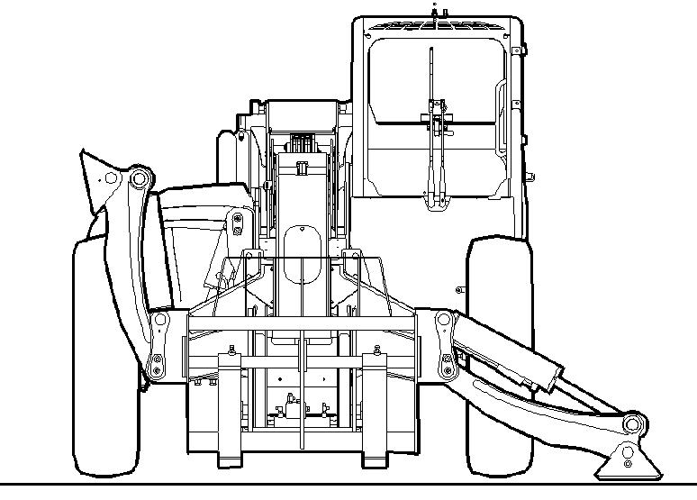
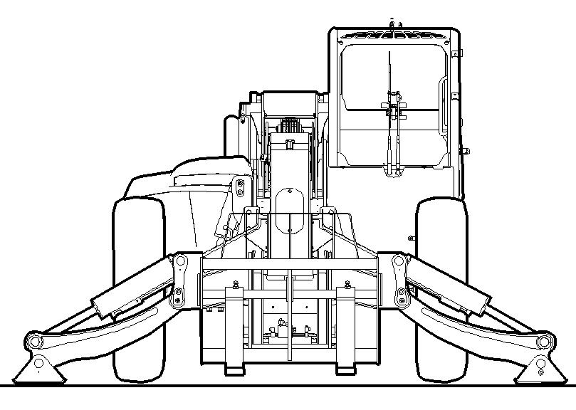
Illustration 69 g00855680
6. Release the switch when the stabilizer has reached the desired position. 7. Adjust the position of the stabilizers in order to level the machine. The machine frame is level when the bubble is in the middle of the level indicator sight glass window. The front tires must remain slightly raised above the ground. Do not attempt to level the machine by operating the frame leveling control when the stabilizers are lowered. Before you raise the stabilizers, fully retract the boom. Then, lower the boom to the travel position. Ensure that both stabilizers are fully raised before you move the machine.
Depress the switch when the auxiliary hydraulics are being operated. This will provide continuous flow to the auxiliary hydraulics. The button on joystick (13) that is pressed will determine the direction of flow. The flow rate is fixed when continuous flow is requested. In order to resume normal operation, depress the switch
Depress the switch when the auxiliary hydraulics are being operated. This will provide continuous flow to the auxiliary hydraulics. The button on joystick (13) that is pressed will determine the direction of flow. The flow rate is fixed when continuous flow is requested. In order to resume normal operation, depress the switch again. Alternately, press one of the buttons on the joystick. Normal operation will resume.
Fog Lights (8)
Fog Lights - Push the right side of switch in order to turn on the fog lights. Push the left side of switch in order to turn off the fog lights.
Hazard Flashers (9)
Hazard Flashers - Push the right side of switch (9) in order to activate the hazard flashers. All the turn signal lights will flash simultaneously. Push the left side of switch (9) in order to deactivate the hazard flashers.
Headlight Dimmer Switch (10)
Dimmer Control - Push the right side of switch (10) in order to activate the high beam headlights. Switch (11) for the headlights must be in the HEADLIGHTS position in order to activate the high beam. The headlights remain on high beam until the left side of switch (10) is pushed to the LOW BEAM position.
Headlight-Parking Lights (11)
Low Beam Headlights - Push the right side of switch (11) in order to turn on the parking lights and the rear lights. Push the right side of switch (11) again in order to turn on the headlights, the parking lights and the rear lights. Push the left side of switch (11) in order to turn off the headlights. Push the left side of switch (11) again in order to turn off the parking lights and the rear lights.
Rotating Beacon Light (12)
Rotating Beacon (if equipped) - Push the right side of switch (12) in order to activate the rotating beacon. Push the left side of switch (12) in order to deactivate the rotating beacon.
Joystick Control (13)
Improper use of the boom and work tools could result in injury or death. The operator must be fully aware of all the functions for the joystick control and proper operating techniques.
The following information describes two types of operating arrangements for the joystick control. A decal that shows the configuration is located forward of joystick control (13). The decal indicates the movements that will be produced when you operate the joystick control.
You must understand all of the functions of the joystick control before you operate the machine. Type A Control Arrangement (Single Thumb Wheel)
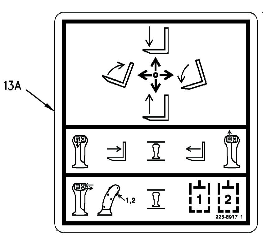
Illustration 70 g00978774 Machines that have the Type A control arrangement are equipped with decal (13A) that is shown above. Joystick control (13) operates in the following way:
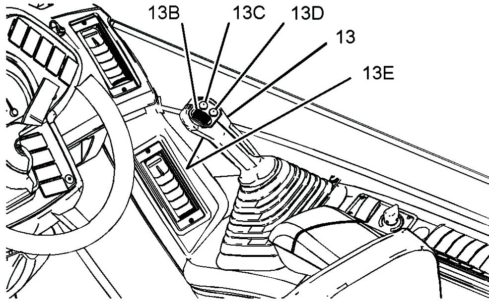
Illustration 71 g01213463
Boom Raise - Pull joystick control (13) backward in order to raise the boom. When joystick control (13) is released, the joystick control will return to the HOLD position. Boom Lower - Push joystick control (13) forward in order to lower the boom. When joystick control (13) is released, the joystick control will return to the HOLD position. Quick Coupler (Tilt Forward) - Push joystick control (13) to the right in order to tilt the quick coupler forward. When joystick control (13) is released, the joystick control will return to the HOLD position.
Quick Coupler (Tilt Backward) - Push joystick control (13) to the left in order to tilt the quick coupler backward. When joystick control (13) is released, the joystick control will return to the HOLD position. Boom Extend - Push thumb wheel (13B) forward in order to extend the boom. When the thumb wheel is released, the thumb wheel will return to the HOLD position.
Note: The boom will not extend when the transmission control is in the REVERSE position. The function for extending the boom will resume if the transmission is neutralized by the service brake, the parking brake, or the transmission neutralizer button. Boom Retract - Pull thumb wheel (13B) backward in order to retract the boom. When the thumb wheel is released, the thumb wheel will return to the HOLD position. Auxiliary Controls - Press switch (13E) in order to toggle between the hydraulic circuits for the auxiliary 1 and auxiliary 2. Press switch (13C) in order to operate an actuator for a work tool in the positive direction. Press switch (13D) in order to operate an actuator for a work tool in the negative direction. Switches (13E), (13C) and (13E) are not operated proportionally.
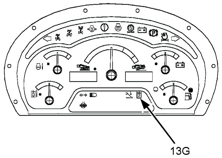
Illustration 72 g01017263
When auxiliary 2 is selected, indicator light (13G) will be illuminated. The speed of the following functions is governed by the amount of movement of the joystick control and engine speed: • Boom raise • Boom lower • Quick coupler (tilt forward) • Quick coupler (tilt backward) For smooth operation, first increase the engine speed from low idle. Then, move joystick control (13) slowly until the attachment is moving at the required speed. The speed of the boom extend and boom retract is governed by the amount of movement of thumb wheel (13B). Move joystick control (13) diagonally in order to simultaneously tilt the quick coupler forward or backward while the boom is being raised or lowered. Move joystick control (13) diagonally. At the same time operate thumb wheel (13B) in order to simultaneously tilt the quick coupler while the boom is being operated in two directions.
Type A Control Arrangement (Double Thumb Wheel)
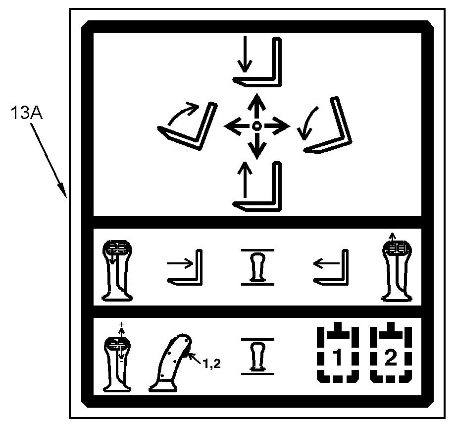
Illustration 73 Film for joystick with double thumb wheel g01051074
Machines that have the Type A control arrangement are equipped with decal (13A) that is shown above. The joystick control operates in the following way:

Illustration 74
g01213466 Boom Raise - Pull the joystick control backward in order to raise the boom. When the joystick control is released the joystick control will return to the HOLD position. Boom Lower - Push the joystick control forward in order to lower the boom. When the joystick control is released the joystick control will return to the HOLD position.
Quick Coupler (Tilt Forward) - Push the joystick control to the right in order to tilt the quick coupler forward. When the joystick control is released the joystick control will return to the HOLD position. Quick Coupler (Tilt Backward) - Push the joystick control to the left in order to tilt the quick coupler backward. When the joystick control is released the joystick control will return to the HOLD position. Boom Extend - Move thumb wheel (13B) forward in order to extend the boom. When the thumb wheel is released the thumb wheel will return to the HOLD position.
Note: The boom will not extend when the transmission control is in the REVERSE position. The function for extending the boom will resume if the transmission is neutralized by the service brake, the parking brake, or the transmission neutralizer button. Boom Retract - Move thumb wheel (13B) backward in order to retract the boom. When the thumb wheel is released the thumb wheel will return to the HOLD position. Auxiliary Controls - If equipped, press switch (13E) in order to toggle between the hydraulic circuits for the auxiliary 1 and auxiliary 2. Move thumb wheel (13C) forward in order to operate an actuator for a work tool in the positive direction. Move thumb wheel (13C) backward in order to operate an actuator for a work tool in the negative direction. Switch (13E) is not operated proportionally.
Illustration 75 g01017263
When auxiliary 2 is selected, indicator light (13G) will be illuminated. The speed of the following functions is governed by the amount of movement of the joystick control and engine speed: • Boom raise • Boom lower • Quick coupler (tilt forward) • Quick coupler (tilt backward) For smooth operation, first increase the engine speed from low idle. Then move joystick control (13) slowly until the attachment is moving at the required speed. The speed of the boom extend and boom retract is governed by the amount of movement of thumb wheel (13B). Move joystick control (13) diagonally in order to simultaneously tilt the quick coupler forward or backward while the boom is being raised or lowered. Move joystick control (13) diagonally. At the same time operate thumb wheel (13B) in order to simultaneously tilt the quick coupler while the boom is being operated in two directions.
Type B Control Arrangement (Single Thumb Wheel)
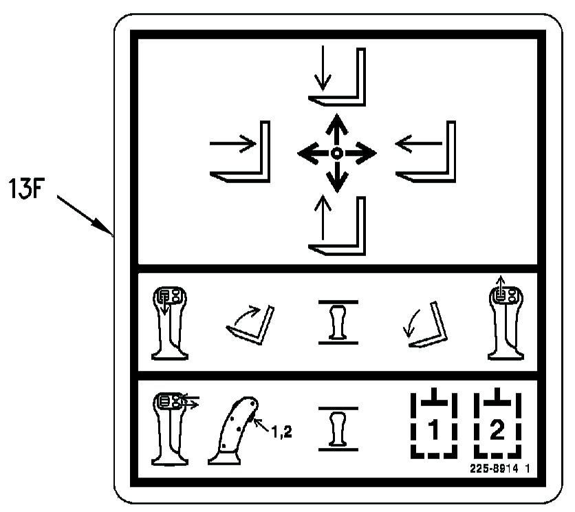
Illustration 76 g00978869
Machines that have the Type B control arrangement are equipped with decal (13F) that is shown above. Joystick control (13) operates in the following way:
Illustration 77 g01213463 Boom Raise - Pull joystick control (13) backward in order to raise the boom. When
joystick control (13) is released, the joystick control will return to the HOLD position. Boom Lower - Push joystick control (13) forward in order to lower the boom. When joystick control (13) is released, the joystick control will return to the HOLD position. Boom Extend - Push joystick control (13) to the right in order to extend the boom. When joystick control (13) is released, the joystick control will return to the HOLD position.
Note: The boom will not extend when the transmission control is in the REVERSE position. The function for extending the boom will resume if the transmission is neutralized by the service brake, the parking brake, or the transmission neutralizer button. Boom Retract - Pull joystick control (13) to the left in order to retract the boom. When joystick control (13) is released, the joystick control will return to the HOLD position. Quick Coupler (Tilt Forward) - Push thumb wheel (13B) forward in order to tilt the quick coupler forward. When the thumb wheel is released, the thumb wheel will return to the HOLD position. Quick Coupler (Tilt Backward) - Pull thumbwheel (13B) rearward in order to tilt the quick coupler backward. When the thumb wheel is released, the thumb wheel will return to the HOLD position.
Auxiliary Controls - Press switch (13E) in order to toggle between the hydraulic circuits for the auxiliary 1 and auxiliary 2. Press switch (13C) in order to operate an actuator for a work tool in the positive direction. Press switch (13D) in order to operate an actuator for a work tool in the negative direction. Switches (13E), (13C) and (13D) are not operated proportionally.
Illustration 78 g01017263 The speed of the following functions is governed by the amount of movement of the joystick control and engine speed: • Boom raise • Boom lower • Boom extend • Boom retract For smooth operation, first increase the engine speed from low idle. Then, move joystick control (13) slowly until the attachment is moving at the required speed. The speed of the quick coupler (tilt forward) and quick coupler (tilt backward) is governed by the amount of movement of thumb wheel (13B). Move joystick control (13) diagonally in order to simultaneously extend the boom or retract the boom while the boom is being raised or lowered. Move joystick control (13) diagonally. At the same time operate thumb wheel (13B) in order to simultaneously tilt the quick coupler while the boom is being operated in two directions.
Type B Control Arrangement (Double Thumb Wheel)
Illustration 79 g01051075 Film for joystick with double thumb wheel
Machines that have the Type B control arrangement are equipped with decal (13F) that is shown above. The joystick control operates in the following way:
Illustration 80 g01213466
Boom Raise - Pull joystick control (13) backward in order to raise the boom. When the joystick control is released the joystick control will return to the HOLD position. Boom Lower - Push joystick control (13) forward in order to lower the boom. When the joystick control is released the joystick control will return to the HOLD position.
Boom Extend - Push joystick control (13) to the right in order to extend the boom. When the joystick control is released the joystick control will return to the HOLD position.
Note: The boom will not extend when the transmission control is in the REVERSE position. The function for extending the boom will resume if the transmission is neutralized by the service brake, the parking brake, or the transmission neutralizer button.
Boom Retract - Pull joystick control (13) to the left in order to retract the boom. When the joystick control is released the joystick control will return to the HOLD position. Quick Coupler (Tilt Forward) - Move thumb wheel (13B) forward in order to tilt the quick coupler forward. When the thumb wheel is released the thumb wheel will return to the HOLD position. Quick Coupler (Tilt Backward) - Move thumbwheel (13B) backward in order to tilt the quick coupler backward. When the thumb wheel is released the thumb wheel will return to the HOLD position. Auxiliary Controls - If equipped, press switch (13E) in order to toggle between the hydraulic circuits for the auxiliary 1 and auxiliary 2. Move thumb wheel (13C) forward in order to operate an actuator for a work tool in the positive direction. Move thumb wheel (13C) backward in order to operate an actuator for a work tool in the negative direction. Switch (13E) is not operated proportionally.
Illustration 81 g01017263
When auxiliary 2 is selected, indicator light (13G) will be illuminated. The speed of the following functions is governed by the amount of movement of the joystick control and engine speed: • Boom raise • Boom lower • Boom extend • Boom retract For smooth operation, first increase the engine speed from low idle. Then move joystick control (13) slowly until the attachment is moving at the required speed. The speed of the quick coupler (tilt forward) and quick coupler (tilt backward) is governed by the amount of movement of thumb wheel (13B). Move joystick control (13) diagonally in order to simultaneously extend the boom or retract the boom while the boom is being raised or lowered. Move joystick control (13) diagonally. At the same time operate thumb wheel (13B) in order to simultaneously tilt the quick coupler while the boom is being operated in two directions.
Adjustable Armrest (14)
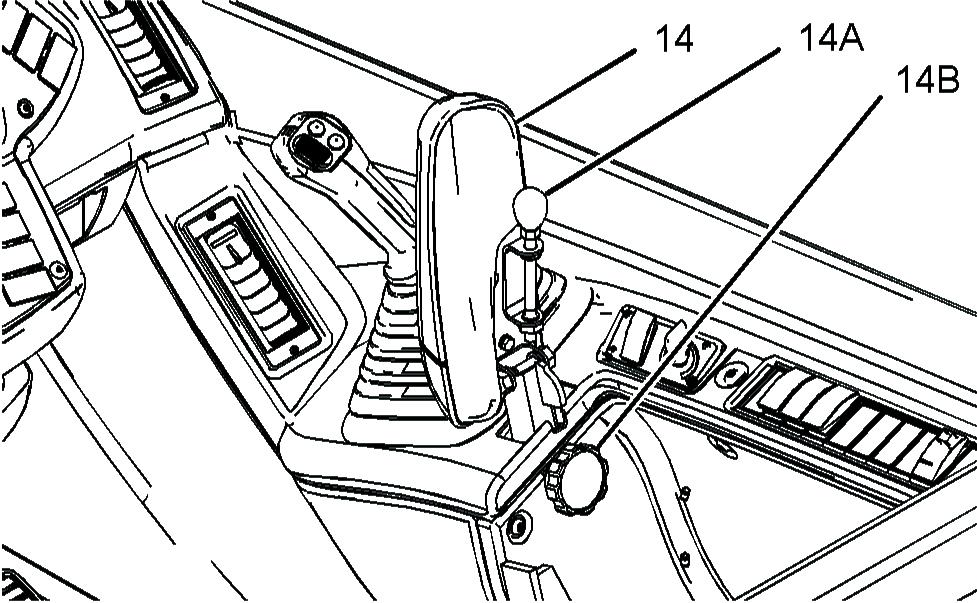
Lift the armrest in order to adjust the armrest. In order to adjust the angle of armrest, rotate knob (14A). To increase the angle of the armrest, turn the knob clockwise. To decrease the angle of the armrest, turn the knob counterclockwise. In order to adjust the height of armrest, loosen knob (14B), and raise the armrest to the desired height. To secure the armrest at the desired height, tighten the knob.
Side Console (15)
The side console contains controls for the following features: • Heating and air conditioning • Window wiper and window washer • Floodlights for the cab • Boom floodlights • Hydraulic towing hitch • Implement lockout • Access platform Refer to Operation and Maintenance Manual, "Operator Controls (Side Console)" for more detailed information on each of these controls.
Interior Light (16)
Interior Light (if equipped) - Press either side of the lens in order to turn on the interior light. Press the opposite side of the lens in order to turn off the interior light.
Parking and Secondary Brake Control (17) Parking Brake
Note: The parking brake operates on the front axle only. Engage the parking brake after the machine has stopped and when the transmission control has been moved to the NEUTRAL position.
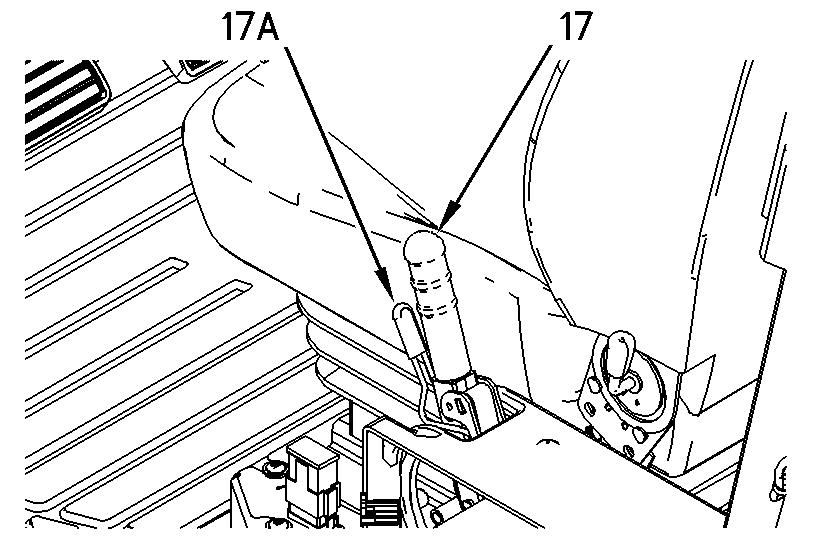
Illustration 83 g00978894 Parking Brake Engaged - Pull lever (17) fully upward in order to engage the parking brake. When the lever is pulled fully upward, a latch will lock in order to hold the parking brake in the ENGAGED position. Parking Brake Disengaged - Pull back lever (17) and pull lever (17A) in order to release the latch. Lower lever (17) to the DISENGAGED position. Note: The parking brake has an interlock switch in order to prevent the machine from being driven through the brake. The machine will not move in either FORWARD or REVERSE when the parking brake is engaged. The machine will not move if the parking brake lever is slightly engaged.
Secondary Brake
The parking brake also functions as a secondary brake. Only use the parking brake to bring the machine to a stop if the service brakes fail to stop the machine. If the parking brake has been used as a secondary brake for an emergency stop, do not move or operate the machine until the service and parking brake systems have been checked and any necessary repairs have been completed.
Accelerator Control (18)
Depress the pedal in order to increase the engine speed. Release the pedal in order to decrease the engine speed.
Service Brake Control (19)
Brakes are installed on the front axle. Depress the pedal in order to decelerate or stop the machine. Release the pedal in order to disengage the service brakes. The service brake can be used in conjunction with transmission neutralizer control (switch) (2). When the top of switch (2) is pushed in, the transmission is automatically neutralized when a firm pressure is applied to the brake pedal. This allows a higher engine speed for improved hydraulic response time when you operate the machine implements. This mode of operation should only be used when the boom is retracted and below horizontal. When the bottom of switch (2) is pushed in, the transmission remains engaged when the pedal is depressed. Refer to "Transmission Neutralizer Control (2)" for more information.
Differential Lock Control (20)
The differential lock can be selected in order to override the normal operation of the front axle differential. The differential lock will help maintain traction when the ground conditions are soft or slippery. When the differential lock is selected, torque is transmitted to both wheels even though one wheel may not have traction. Differential Lock Control - Press the control and hold the control in order to engage the differential lock. In order to disengage the
differential lock, release pressure from accelerator pedal (18) and release differential lock control.
NOTICE Use the differential lock only in conditions where wheel spin has, or will be encountered. If wheel spin has already developed, release pressure from the accelerator pedal and allow the engine speed to fall sufficiently to stop wheel spin before engaging the differential lock. Failure to follow this procedure can result in machine damage. Keep steering maneuvers to a minimum when the differential lock is engaged. Steering maneuvers with the differential lock engaged can result in machine damage.
The differential lock should only be engaged with all of the wheels in the straight ahead position. The differential lock should only be engaged when the machine is stopped.
Transmission Control (21) Direction Selection
Forward (F) - Push the lever fully upward (F) in order to select forward movement.
Neutral (N) - Move the lever to the midposition in order to select NEUTRAL.Move the lever to the NEUTRAL position when you park the machine. The lever must be in the NEUTRAL position before the engine can be started. Reverse (R) - Pull the lever fully downward in order to select reverse movement.
Speed Selection Powersynchro Transmission
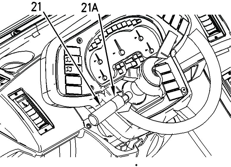
Illustration 84 g00978904 transmission speed is opposite the line. All four speeds can be selected for forward travel. The first three speeds can be selected for reverse travel. Select the proper speed for the application.
Manual Transmission
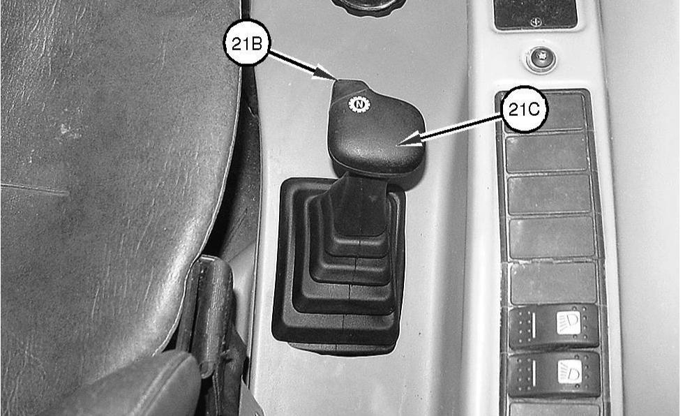
Illustration 85 g01014289
Some machines are equipped with a manual transmission shift. Transmission Neutralizer Button (21B) Push the button and hold the button when you are changing speed ranges. This will disengage the transmission from the driving wheels.
Transmission Speed Shift Lever (21C) - Push transmission neutralizer button (21B) and hold button (21B) in order to neutralize the transmission. Then, move lever (21C) to one of the four desired travel speeds. All four speeds can be selected in both forward and reverse travel. Speed changes are possible when you are moving and when the machine is at full engine speed.
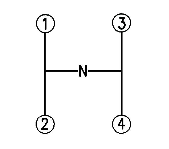
Illustration 86 g00846950
Move the transmission speed lever according to the shift pattern in Illustration 86.
Changing Speed and Direction
Start moving the machine in first gear or in second gear. To upshift, move the transmission control to the next highest gear. It is not necessary to release the accelerator control. To downshift, move the
transmission control to the next lowest gear. Do not skip gears when you down shift. Continue to shift through the gears in this way as the conditions are required. To prevent engine overspeed, do not downshift if the engine speed is high. Control the speed of the machine in order to suit conditions. Make an allowance for surface conditions, weather conditions and load.
Note: The machine should be in first speed or second speed when you change the direction of the machine from forward to reverse or from reverse to forward.
Select the correct gear before you travel downhill. Select the necessary travel speed before you start downhill. Do not change gears while you are going downhill. When you go downhill, use the same speed that would be used to go uphill. Do not allow the engine to overspeed when you go downhill. Use the service brake to prevent engine overspeed when you go downhill. Select a lower gear before you go down the same hill again.
When you are travelling uphill, select a lower gear when the engine speed starts to fall. Drive the machine in the gear that will allow the required speed to be maintained. Do not allow the torque converter to slip and do not allow the engine to lug. Note: When the torque converter is stalled due to an excessive load, down shifting will not change the gear until the service brake has been applied.
Horn (22)
Horn - Push the horn in order to sound the horn. Use the horn in order to alert personnel. Also, use the horn in order to signal personnel.
Starting Aid Switch (23)
SLE1-1250 Starting Aid Switch - Switch (23) is a momentary switch. Push in the left side of switch (23) in order to activate the air inlet heater. Refer to Operation and Maintenance Manual, "Engine Starting" for the correct procedure to start the engine when the air inlet heater is required.
Auto/Manual Switch (24) (If Equipped)
SLE1350-Up Auto/Manual Switch - This is a two-position switch. If your machine is equipped with the Powersynchro transmission, this switch is an option on your machine. Push the left side of the switch in order to select automatic shifting between the gears of the transmission. The operator will select the highest speed range and the machine ECM will automatically shift the transmission between the lowest gears to the highest gear that has been selected, based on ground speed of the machine. A lamp inside the switch will be illuminated. Push the right side of the switch in order to manually select a specific speed gear.
Directional Turn Signal Control (25)
Directional Turn Signal - Push up on the switch in order to activate the left turn signal. Pull down on the switch in order to activate the right turn signal. The mid-position is the OFF position. Note: The turn signal only operates when engine start switch (26) is in the ON position.
Engine Start Switch (26)
Electrical power is supplied to the systems in the cab when the engine start switch has returned from the START position to the ON position. OFF - When you insert the engine start switch key and when you remove the engine start switch key, the engine start switch must be in the OFF position. To disconnect the power to the electrical circuits in the cab, turn the engine start switch key to the OFF position. Also, turn the engine start switch key to the OFF position in order to stop the engine. When the key is in the OFF position the following circuits remain activated: • Hazard warning • Interior light • Parking lights Turn the engine start switch key clockwise to the ON position in order to activate all electrical circuits except the starting motor circuit. Before the engine will start, transmission control (21) must be in the NEUTRAL position. To start the engine, turn the engine start switch key clockwise from the ON position to the START position. Release the engine start switch after the engine starts. The engine start switch will return to the ON position.
Note: If the engine fails to start, return the engine start switch key to the OFF position. Wait for twenty seconds before you attempt to start the engine again. This will allow the monitoring system to reset. Note: As the machine powers up the machine goes through a number of self test and system checks. The hydraulic functions are not available for operation for four seconds until the self test is completed.
Your machine may be equipped with a security system. When a security system is installed, only the correct electronically programmed key will start the engine.
Steering Column Tilt Control (27)
Move lever (27) upward in order to unlock the steering column. Pivot the steering column to the desired position. Move lever (27) downward in order to lock the steering column in place. Always lock the steering column before you move the machine or before you operate the machine.
Power Receptacle (28)
Power Receptacle - A twelve volt power receptacle is located at the bottom of the console for the parking brake. An external twelve volt power receptacle is located on the upper, left rear of the cab. The power receptacles can be used to power automotive electrical equipment or accessories. Remove the cap before use.
Note: Twelve volt power supply is only available when the engine start switch is in the ON position.
Machine Security System (If Equipped)
NOTICE This machine is equipped with a Caterpillar Machine Security System (MSS) and may not start under certain conditions. Read the following information and know your machine's settings. Your Caterpillar dealer can identify your machine settings.
Machine Security System (MSS) - Machines that are equipped with a Caterpillar Machine Security System (MSS) can be identified by a decal in the operator station. MSS is designed to prevent theft of the machine or unauthorized operation.
Basic Operation
MSS may be programmed to read a standard Caterpillar key or an electronic key. The electronic key contains an electronic chip within the plastic housing for the key. Each key emits a unique signal to the MSS. The keys can be identified by a gray housing or a yellow housing. MSS can have programmed settings to require an electronic key or a standard Caterpillar key for starting during certain periods of time. When the key start switch of the machine is turned to the ON position, the ECM will read the unique ID that is stored in the electronic key. The ECM will then compare this ID to the list of authorized keys. The following table tells the operator the status for starting the machine. The status light is located near the key start switch.
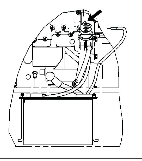
Table 9
Green light The machine will start. Red light The key is not authorized. Note: MSS will not shut down the machine after the machine has started.
Security Management
The MSS has the capability to allow you to program the system to automatically activate at different time periods with different keys. The MSS can also be programmed to reject a specific electronic key after a selected date and time. When you turn the key to the OFF position and the MSS is active, you have a 30 second interval in order to restart the machine with an unauthorized key. Also if the machine stalls, there is a 30 second interval for restarting the machine. This 30 second interval is counted from the time of turning the key to the OFF position.
Note: Know your machine's settings because the use of an electronic key is no guarantee that the machine can be restarted. An expiration date can be set for each electronic key that is contained in the list of keys for the machine. The key will no longer start the machine when the internal clock in the security system passes the expiration date. Each entry in the list of keys can have a different expiration date. Spare keys are available from your dealer. Before a key can operate the machine, the MSS must be set to accept that particular key. Consult your Caterpillar dealer for information on additional features of the MSS.
Battery Disconnect Switch (If Equipped)
Open the engine enclosure on the right side of the machine. The battery disconnect switch is located on the right side of the engine compartment above the battery.
Illustration 87 g00951966 Battery disconnect switch
ON - Insert the battery disconnect switch key, and turn the battery disconnect switch key clockwise in order to activate the electrical system. The switch must be ON before you start the engine.
OFF - Turn the battery disconnect switch key counterclockwise in order to shut off the entire electrical system.
The battery disconnect switch and the engine start switch serve different functions. When the battery disconnect switch is turned off, the entire electrical system is disabled. When only the engine start switch is turned off, the battery remains connected to the electrical system. Turn the battery disconnect switch key to the OFF position and remove the battery disconnect switch key when you service the electrical system or you service any other components of the machine. Turn the battery disconnect switch key to the OFF position and remove the battery disconnect switch key when the machine is left for a period of one month or longer. Adopt this procedure in order to prevent the following circumstances: • A short circuit from draining the battery • Active components from draining the battery • Draining of the battery through vandalism Note: The battery disconnect switch should never be disconnected while the machine is running.
Rear Axle Lock (If Equipped)
S/N: SLE1-Up
Operating the machine beyond its stability limit could result in a tip over or failure of the work tool Check the proposed lift with the load chart. Do not attempt the lift if the longitudinal stability limit of the machine will be exceeded. Tip over or failure of the work tool could cause personnel injury or death.
Engage the parking brake when the rear axle is in the locked axle mode. Failure to engage the parking brake could allow the machine to move and/or tip over. Machine movement or tip over could result in personal injury or death.
The Rear Axle Lock (RAL) on the Telehandler is designed to improve the lateral stability of the machine when the machine is lifting heavy loads to high elevations. The operation of the RAL is completely automatic. There is no indication to the operator when the RAL is engaged. The RAL has three major modes of operation. • Free Axle • Limited Free Axle • Locked Axle
Free Axle
This mode is equivalent to a machine that is operating without a RAL. The rear axle can pivot freely. The machine will remain in this mode until the boom is raised above the critical angle or until the engine is switched off.
Limited Free Axle
This mode is the equivalent to a machine that is operating in the free axle mode with the following exception. Both of the functions for the boom raise and the boom extend/retract are disabled. This mode occurs when the boom is raised above the critical angle and when the transmission is engaged. If the boom is lowered in this mode the machine will change into the free axle mode. If the transmission control is placed into neutral and the parking brake is applied the machine will change into locked axle mode.
Locked Axle
This mode fixes the rear axle rigidly to the frame by preventing any hydraulic flow from the rear axle lock cylinder. The following operating conditions must be applied in order to place the machine into the locked axle mode: • The transmission control must be in NEUTRAL position. • The parking brake must be applied. • If equipped, the frame level must be disabled. • The boom must be raised above the critical angle. In this mode, the operator has the full operation of the boom. It is not possible to engage the transmission in this mode until the boom is lowered below 45 degrees. Lowering the boom below 45 degrees will yield free axle mode.
Note: An alarm will sound if the parking brake is disengaged with the machine in locked axle mode. The alarm will sound in order to warn the operator that the machine has been placed in a potentially unsafe condition. The alarm will cease when the parking brake is engaged.
Limp Home Mode
A limp home mode for a failure of the boom angle sensor is provided. The limp home mode provides a procedure for returning the machine to the free axle mode if there is a failure of the boom angle sensor. If the boom angle sensor fails the operator will be alerted with a level 2S error code on the display panel. Before you move the machine you must ensure that the boom is below an angle of 45 degrees.
Use the following procedure in order to move the machine to a safe location. 1. Ensure that the transmission speed control is in the NEUTRAL position. 2. Engage the parking brake. 3. Lower the boom until the boom is below an angle of 45°. 4. Move the transmission speed control through the following positions: • NEUTRAL position • FIRST position • NEUTRAL position • FIRST position Note: This sequence must be executed within two seconds in order to be successful. The transmission can now be engaged. 5. The machine should now be moved to a suitable location in order to repair the boom angle sensor.
Repair the boom angle sensor before returning the machine to operation.
Note: The double shift sequence will be required to be repeated if the transmission speed control is moved into NEUTRAL position.
Boom Cylinder Lock (If Equipped)
A raised boom can fall if a hydraulic component is removed. Sudden movement of the boom could cause personal injury or death. Remove any load from the work tool, retract the boom and install the boom cylinder lock or a suitable supporting stand before working under a raised boom.
When you are working under the boom it is necessary to install a boom cylinder lock on the boom cylinder.
Installation and Removal Procedures Installation
1. Park the machine on level ground. Retract and lower the boom. Move the transmission control to
NEUTRAL. Engage the parking brake. 2. Raise the boom to an angle of approximately 20 degrees. Stop the engine. Remove the engine start switch key. If equipped, remove the battery disconnect switch key. install the boom cylinder lock. Clean the area, if necessary. 3. Check that the cylinder lock is the correct type for your machine. Inspect the boom cylinder lock for damage. Inspect pad (4). Do not use the cylinder lock if the cylinder lock is damaged or if pad (4) is loose or missing. 4. Place the cylinder lock onto the top of the main frame above the front axle. Allow sufficient access to stand on the flat area of the frame. Make sure that both of your hands are free. Approach the machine from the front. Use the fender bracket (if equipped) and the edge of the main frame for support. Step onto the axle. Then, step onto the top of the main frame. Use the nonslip treads that are provided.
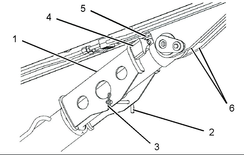
Illustration 88 g01071433
5. Install boom cylinder lock (1) onto the boom cylinder.
Insert pin (2) and retaining clip (3). Align boom cylinder lock (1). Location tongue (5) must pass between boom plates (6) when the boom is lowered.
Note: When you descend from the machine, use the supports and use the nonslip treads, in the same manner that is indicated in the previous steps.
6. Replace the battery disconnect switch key (if equipped) and the engine start key. 7. Start the engine. Lower the boom slowly. Make sure that location tongue (5) passes between boom plates (6). Lower the boom until there is a clearance of 6 mm (0.25 inch) between the boom plates (6) and the yellow nylon pad (4).
NOTICE Do not operate the boom with the boom cylinder lock installed. Operating the boom with the boom cylinder lock installed will damage the boom cylinder lock and the boom cylinder.